Induktiver Drehzahlsensor I MSZ214 - metes technology GmbH
Induktiver Drehzahlsensor I MSZ214 - metes technology GmbH
Induktiver Drehzahlsensor I MSZ214 - metes technology GmbH

Erfolgreiche ePaper selbst erstellen
Machen Sie aus Ihren PDF Publikationen ein blätterbares Flipbook mit unserer einzigartigen Google optimierten e-Paper Software.
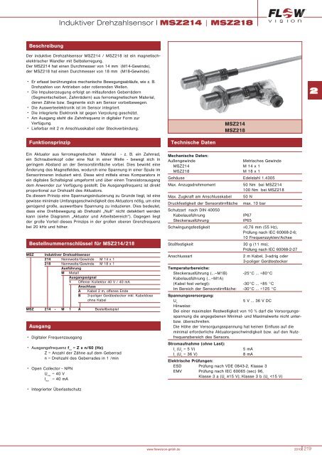
<strong>Induktiver</strong> <strong>Drehzahlsensor</strong> I <strong>MSZ214</strong> | MSZ218<br />
<strong>MSZ214</strong> | MSZ218<br />
Beschreibung<br />
Der induktive <strong>Drehzahlsensor</strong> <strong>MSZ214</strong> / MSZ218 ist ein magnetischelektrischer<br />
Wandler mit Selbsterregung.<br />
Der <strong>MSZ214</strong> hat einen Durchmesser von 14 mm (M14-Gewinde),<br />
der MSZ218 hat einen Durchmesser von 18 mm (M18-Gewinde).<br />
• Er erfasst berührungslos mechanische Bewegungsabläufe, wie z. B.<br />
Drehzahlen von Antrieben oder rotierenden Wellen.<br />
• Die Impulserzeugung erfolgt an mitlaufenden Geberrädern<br />
(Segmentscheiben, Zahnrädern) aus ferromagnetischem Material,<br />
deren Zähne bzw. Segmente sich am Sensor vorbeibewegen.<br />
• Die Auswerteelektronik ist im Sensor integriert.<br />
• Die integrierte Elektronik ist gegen Verpolung geschützt.<br />
• Am Ausgang steht die Zahnfrequenz in digitaler Form zur<br />
Verfügung.<br />
• Lieferbar mit 2 m Anschlusskabel oder Steckverbindung.<br />
<strong>MSZ214</strong><br />
MSZ218<br />
2<br />
Funktionsprinzip<br />
Ein Aktuator aus ferromagnetischen Material - z. B. ein Zahnrad,<br />
ein Schraubenkopf oder eine Nut in einer Welle - bewegt sich in<br />
geringem Abstand an der Sensorstirnfläche vorbei. Dies bewirkt eine<br />
Änderung des Magnetfeldes, wodurch eine Spannung in einer Spule im<br />
Sensorinneren induziert wird. Diese wird mittels eines Komparators in<br />
ein digitales Schaltsignal umgeformt und über einen Transistorausgang<br />
dem Anwender zur Verfügung gestellt. Die Ausgangsfrequenz ist direkt<br />
proportional zur Drehzahl des Aktuators.<br />
Da diesem Prinzip eine Spannungsinduzierung zu Grunde liegt, ist eine<br />
gewisse minimale Umfangsgeschwindigkeit des Aktuators nötig, um eine<br />
genügend große, auswertbare Spannung zu induzieren. Dies bedeutet,<br />
dass eine Drehbewegung ab Drehzahl „Null“ nicht detektiert werden<br />
kann (siehe Diagramm „Aktuator und Arbeitsbereich“). Dagegen liegt<br />
der große Vorteil dieses Prinzips in der großen oberen Grenzfrequenz<br />
bei 20 kHz und höher.<br />
Bestellnummernschlüssel für <strong>MSZ214</strong>/218<br />
MSZ<br />
<strong>Induktiver</strong> <strong>Drehzahlsensor</strong><br />
214 Nennweite/Gewinde M 14 x 1<br />
218 Nennweite/Gewinde M 18 x 1<br />
Ausführung<br />
M Metall<br />
Ausgangssignal<br />
1 Offener Kollektor 40 V / 40 mA<br />
Anschluss<br />
A Kabel 2 m, offenes Ende<br />
B 3-poliger Gerätestecker inkl. Kabeldose<br />
ohne Kabel<br />
MSZ 214 - M 1 A Bestellbeispiel<br />
Ausgang<br />
• Digitaler Frequenzausgang<br />
• Ausgangsfrequenz f out<br />
= Z x n/60 (Hz)<br />
Z = Anzahl der Zähne auf dem Geberrad<br />
n = Drehzahl des Geberrades in 1 /min<br />
• Open Collector - NPN<br />
U max<br />
= 40 V<br />
I max<br />
= 40 mA<br />
Technische Daten<br />
Mechanische Daten:<br />
Außengewinde<br />
Metrisches Gewinde<br />
<strong>MSZ214</strong> M 14 x 1<br />
MSZ218 M 18 x 1<br />
Gehäuse Edelstahl 1.4305<br />
Max. Anzugsdrehmoment<br />
Max. Zugkraft am Anschlusskabel<br />
Druckfestigkeit der Sensorstirnfläche<br />
Schutzart nach DIN 40050<br />
Kabelausführung<br />
Steckerausführung<br />
Schwingungsfestigkeit<br />
Stoßfestigkeit<br />
Anschlussart<br />
50 Nm bei <strong>MSZ214</strong><br />
100 Nm bei MSZ218<br />
50 N<br />
max. 10 bar<br />
IP67<br />
IP65<br />
±0,76 mm (55 Hz),<br />
Prüfung nach IEC 60068-2-6;<br />
10 Frequenzzyklen/Achse<br />
30 g (11 ms);<br />
Prüfung nach IEC 60068-2-27<br />
2 m Kabel, 3-adrig oder<br />
3-poliger Gerätestecker<br />
Temperaturbereiche:<br />
Steckerausführung (…–M1B) -25°C ... +80°C<br />
Kabelausführung (…–M1A)<br />
(Kabel fest verlegt): -30°C ... +85 °C<br />
Im Bereich der Sensorstirnfläche: -30°C ... +125 °C<br />
Spannungsversorgung:<br />
U b<br />
5 V ... 36 V DC<br />
Hinweise:<br />
Bei einer maximalen Restwelligkeit von 10 % darf die Versorgungsspannung<br />
die angegebenen Minimal- und Maximalwerte nicht unterbzw.<br />
überschreiten.<br />
Die Höhe der Versorgungsspannung hat keinen Einfluss auf die<br />
minimal erforderliche Aktuatorgeschwindigkeit bzw. auf den Nutzfre<br />
quenz bereich des Sensors.<br />
Stromaufnahme (ohne Last):<br />
I o<br />
(U b<br />
= 5 V)<br />
I o<br />
(U b<br />
= 36 V)<br />
5 mA<br />
8 mA<br />
Elektrische Prüfungen:<br />
ESD Prüfung nach VDE 0843-2, Klasse 3<br />
EMV Prüfung nach IEC 60065 (sec) 96,<br />
Klasse 3 a (U b<br />
≥15 V); Klasse 3 b (U b<br />
<strong>Induktiver</strong> <strong>Drehzahlsensor</strong> I <strong>MSZ214</strong> | MSZ218<br />
Aktuator und Arbeitsbereich<br />
Anschlussbild<br />
V min<br />
m<br />
s<br />
. 10 -3 = mm s<br />
500<br />
2<br />
450<br />
400<br />
350<br />
MSZ<br />
+U B<br />
Ausgang<br />
GND<br />
RL<br />
+U b 5 … 36 V<br />
Ausgang<br />
GND<br />
300<br />
250<br />
200<br />
Uextern ≤ 40 V<br />
150<br />
RL<br />
U extern GND<br />
100<br />
+U B<br />
Ausgang<br />
+U b 5 … 36 V<br />
Ausgang<br />
50<br />
MSZ<br />
GND<br />
GND<br />
0<br />
0,2 0,4 0,6 0,8 1,0 1,2 1,4 1,6 1,8 2<br />
a (mm)<br />
Die minimale vom Sensor erfassbare Aktuatorgeschwindigkeit V min<br />
ist<br />
eine Funktion des Abstandes a (Sensor - Geberrad).<br />
Die Funktion des Sensors ist weitgehend unabhängig von der<br />
Geometrie des Geberrades. Ein Mindestabstand der Zähne von ca. 2,5<br />
mm sollte eingehalten werden.<br />
Die max. Frequenz, die der Sensor verarbeitet, beträgt 20 kHz.<br />
Maßbilder<br />
<strong>MSZ214</strong>-M1A<br />
<strong>MSZ214</strong>-M1B<br />
ca. 33,5<br />
55 2 m<br />
45<br />
M14x1<br />
ø5,2<br />
braun: U B<br />
schwarz: Ausgang<br />
blau: GND<br />
M14x1<br />
SW 22<br />
SW 22 1.4305<br />
LIYY 3x0,5 mm 2<br />
MSZ218-M1A<br />
MSZ218-M1B<br />
Steckerbelegung:<br />
1 - U B<br />
2 - Ausgang<br />
3 - GND<br />
M18x1<br />
M18x1<br />
SW 27<br />
SW 27<br />
Die zur Verfügung gestellten Informationen sind nach unserem Wissen genau und zuverlässig,<br />
jedoch übernimmt FlowVision keine Verantwortung für den Einsatz in einer Anwendung,<br />
die nicht der vorliegenden Spezifikation entspricht. FlowVision behält sich das Recht vor,<br />
Spezifikationen im Sinne des technischen Fortschritts jederzeit zu ändern. Maßänderungen<br />
sind vorbehalten, bei Bedarf bitte neuestes Maßblatt mit Toleranzen anfordern. Maße, Daten,<br />
Abbildungen und Beschreibung entsprechen dem neuesten Stand bei Herausgabe dieses<br />
Kataloges, sind aber unverbindlich! Änderungen sowie auch Irrtümer und Druckfehler vorbehalten.<br />
Die Bestellbezeichnung der Geräte kann von deren Beschriftung abweichen.<br />
220 2010 www.flowvision-gmbh.de
Inductive Velocity Sensor <strong>MSZ214</strong>/218<br />
Description<br />
Velocity sensors <strong>MSZ214</strong> and MSZ218 are electro-magnetic<br />
transducers with self excitation.<br />
<strong>MSZ214</strong> has a diameter of 14 mm (M14 thread) and MSZ218 a<br />
diameter of 18 mm (M18 thread).<br />
Features<br />
● Contactless sensing of mechanical motion such as the rotational<br />
speed of drives or shafts.<br />
● Pulses are generated by the movement of ferrous gear teeth, for<br />
example, as they pass the sensor head.<br />
● The electronic control circuitry and sensor head are designed as an<br />
integral unit.<br />
● The electronic control circuitry is reverse polarity protected.<br />
● A digital output is available corresponding to the frequency of<br />
movement past the sensor.<br />
● Available either with 2 m permanent cable or with 3-pole connector<br />
<strong>MSZ214</strong><br />
MSZ218<br />
Mode of operation<br />
A ferro magnet actuator such as a gear, screw-head or slot in a shaft,<br />
passes near to the sensor face, causing the magnetic field to change<br />
such that voltage is induced in the coil of the sensor. This voltage is<br />
converted into a digital output signal by means of a comparator and<br />
made available to the user via a transistor output. The output<br />
frequency is directly proportional to the actuator speed.<br />
As this principle is based on voltage induction, the actuator needs to<br />
have a certain minimum circumferential speed in order to induce a<br />
voltage high enough to be evaluated. A rotational motion from “zero”<br />
speed cannot therefore be detected (see diagram “Operating range”<br />
on next page). The benefit of this principle is the high upper frequency<br />
limit of > 20 kHz.<br />
Ordering information<br />
Type No.<br />
MSZ<br />
Inductive Velocity Sensor<br />
214 diameter/thread M14x1<br />
218 diameter/thread M18x1<br />
Version<br />
M stainless steel 1.4305/AISI 303<br />
Output signal<br />
1 open collector 40 V/40 mA<br />
Connection<br />
A 2 m cable, with open end<br />
B 3-pole connector with cable box,<br />
without cable<br />
MSZ 214 - M 1 A ordering example<br />
Output<br />
Digital frequency output<br />
Output frequency<br />
Open collector - NPN<br />
f out = Z x n/60 (Hz)<br />
Z = number of teeth on the pick-up<br />
n = rotational speed of the pick-up in 1/min (rpm)<br />
U max = 40 V<br />
I max = 40 mA<br />
With integral overload protection.<br />
Technical data<br />
Mechanical data:<br />
Outer thread<br />
metric<br />
<strong>MSZ214</strong><br />
M 14x1<br />
MSZ218<br />
M 18x1<br />
Housing stainless steel 1.4305/AISI 303<br />
Max. tightening torque<br />
50 Nm with <strong>MSZ214</strong><br />
100 Nm with MSZ218<br />
Max. pull out force<br />
(connection cable)<br />
50 N<br />
Max. pressure (sensor face) 25 bar/362.5 PSI<br />
Degree of protection<br />
(IEC 529/DIN 40050)<br />
with cable<br />
IP67<br />
with connector<br />
IP65<br />
Vibration<br />
±0.76 mm (55 Hz),<br />
to IEC 60068-2-6;<br />
10 frequency cycles/axis<br />
Shock<br />
30 g (11 ms)<br />
to IEC 60068-2-27<br />
Connection<br />
2 m three-wire cable or<br />
3-pole connector<br />
Temperature ranges:<br />
with connector -25 °C...+80 °C<br />
with cable permanently<br />
connected -30 °C...+85 °C<br />
sensor face area -30 °C...+125 °C<br />
Voltage supply:<br />
U b<br />
DC 5 V...36 V<br />
Notes:<br />
The max. admissible residual ripple is 10 %, but not less than the<br />
minimum voltage or more than the maximum voltage.<br />
The supply voltage has no influence on the minimum required<br />
actuator speed and the useful frequency range of the sensor.<br />
Supply current (without load):<br />
I o (U b = 5 V) 5 mA<br />
I o (U b = 36 V) 8 mA<br />
Electrical tests:<br />
ESD - test to VDE 0834-2, class 3<br />
EMC - test to IEC 60065(sec)96,<br />
class 3 a (U b ≥ 15 V); class 3 b (U b
Inductive Velocity Sensor <strong>MSZ214</strong>/218<br />
Actuator/Operating range<br />
Connection diagrams<br />
Actuator speed<br />
m . s 10 -3 = mm<br />
s<br />
500<br />
1.64<br />
ft.<br />
s<br />
Load input diagram with the sensor connected to the supply<br />
450<br />
1.48<br />
400<br />
1.31<br />
350<br />
1.15<br />
MSZ 214<br />
+U B<br />
output<br />
GND<br />
R L<br />
+U b DC 5…36 V<br />
output<br />
GND<br />
300<br />
.984<br />
V min<br />
0.2<br />
250<br />
.820<br />
200<br />
.656<br />
150<br />
.492<br />
100<br />
.328<br />
50<br />
.164<br />
0<br />
.008<br />
0.4<br />
.016<br />
0.6<br />
.024<br />
0.8<br />
.031<br />
1.0<br />
.039<br />
1.2<br />
.047<br />
1.4<br />
.055<br />
1.6<br />
.063<br />
distance between actuator and sensor<br />
1.8 2.0<br />
.071 .079<br />
a (mm)<br />
(inch)<br />
Load output diagram with the sensor connected to a separate<br />
supply<br />
Uextern ≤40 V<br />
R L U extern GND<br />
+UB<br />
+Ub DC 5…36 V<br />
output<br />
output<br />
GND<br />
GND<br />
MSZ 214<br />
3<br />
The minimum actuator speed V min that can be measured by the<br />
sensor is a function of distance a (between sensor and pick-up).<br />
The function of the sensor is largely independent of the pick-up<br />
geometry. A minimum distance between the teeth of approx.<br />
2.5 mm should be observed.<br />
The max. frequency processed by the sensor is 20 kHz.<br />
Dimension diagrams<br />
<strong>MSZ214</strong>-M1A<br />
55 2 m<br />
2.16 6.56 ft.<br />
<strong>MSZ214</strong>-M1B<br />
approx. 33.5<br />
approx. 1.32<br />
M14x1<br />
ø5.2<br />
.205<br />
brown: U B<br />
black: output<br />
blue: GND<br />
M14x1<br />
SW 22/.866 in.<br />
45<br />
1.77<br />
1.4305<br />
LIYY 3x0.5 mm 2<br />
SW 22/.866 in.<br />
MSZ218-M1A<br />
MSZ218-M1B<br />
terminal selection:<br />
1 - U B<br />
2 - output<br />
3 - GND<br />
M18x1<br />
M18x1<br />
SW 27/1.06 in.<br />
SW 27/1.06 in.<br />
This is a metric design and millimeter dimensions take precedence ( mm )<br />
inch<br />
All dimensions without tolerances are for reference only. In the interest of improved design,<br />
performance and cost effectiveness the right to make changes in these specifications without<br />
notice is reserved. Product markings may not be exactly as the ordering codes. Errors and<br />
omissions excepted.<br />
3 - 4<br />
www.e-t-a.com<br />
Issue A(090807)