Elektronik-Schutzschaltrelais E-1071-128 6
Elektronik-Schutzschaltrelais E-1071-128 6
Elektronik-Schutzschaltrelais E-1071-128 6
- No tags were found...

You also want an ePaper? Increase the reach of your titles
YUMPU automatically turns print PDFs into web optimized ePapers that Google loves.
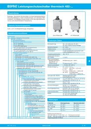
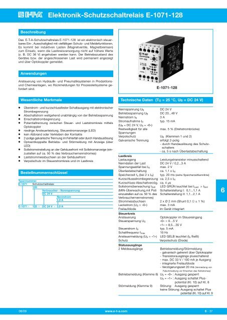
<strong>Elektronik</strong>-<strong>Schutzschaltrelais</strong> E-<strong>1071</strong>-<strong>128</strong>BeschreibungDas E-T-A-<strong>Schutzschaltrelais</strong> E-<strong>1071</strong>-<strong>128</strong> ist ein elektronisch steuerbaresEin-, Ausschaltglied mit vielfältigen Schutz- und Meldefunktionen.Es kommt bei induktiven Lasten (Magnetventile, Magnetbremsen)zum Einsatz, wenn die Lastkreisversorgung nicht auf höhere Werte(z. B. DC 36 V) angehoben werden kann. Der Betriebszustand desGerätes bzw. der angeschlossenen Last wird permanent angezeigtund über Optokoppler gemeldet.AnwendungenAnsteuerung von Hydraulik- und Pneumatiksystemen in ProduktionsundChemieanlagen, wo Rückmeldungen für Prozessleitsysteme gefordertsind.E-<strong>1071</strong>-<strong>128</strong>●●●●●●●●●●●Wesentliche MerkmaleÜberstrom- und kurzschlussfester Schaltausgang mit elektronischerStrombegrenzungAbschaltstrom weitgehend unabhängig von der Betriebs spannungEinschaltstrombegrenzungPotentialtrennung zwischen Steuer- und Laststromkreis mittelsOptokopplerniedrige Ansteuerleistung, Steuerstromanzeige (LED)kein Abbrand oder Verkleben der Kontakte2-polige galvanische Trennung im Fehlerfall oder durch HandauslösungOptoentkoppelte Betriebs- und Störmeldung mit Anzeige (überLED)Sollstromeinstellung an der Gehäusefront mit Sollstromanzeige (einzustellenauf ca. 50 % des Verbrauchernennstromes)Laststrommessbuchsen an der GehäusefrontVerpolschutz im Steuerstromkreis und im LastkreisBestellnummernschlüsselTypennummerE-<strong>1071</strong> <strong>Schutzschaltrelais</strong><strong>128</strong>Verbraucher - NennspannungDC 24 VNennstrom3,0 AE-<strong>1071</strong> - <strong>128</strong> - DC 24 V - 3,0 ATechnische Daten (TU = 25 °C, UB = DC 24 V)Nennspannung U NDC 24 VBetriebsspannung U B DC 20...48 VNennstrom I N3 AStromaufnahme I 0typ. 15 mA(U B = DC 24 V, U S = »0«)Restwelligkeit für alle max. 5 % (Drehstrombrücke)SpannungenVerpolschutz U B (Klemmen 1 und 2)Galvanische Trennung erfolgt 2-polig- durch Handauslösung des Schutzschalters- ca. 5 s nach ÜberlastabschaltungLastkreisLastausgangLeistungstransistor minusschaltendNenndaten der Last DC 24 V / 0,2...3 ASpannungsabfall bei I N max. 2 VÜberlastabschaltung ca. 1,1 x I NSpeicherzeit t s (bei 2 x I N ) typ. 20 ms (siehe Speicherzeitkennlinie)Kurzschlussstrombegrenzung ca. 2,5 x I NKurzschluss-Abschaltverzög. ca. 4 μsSollstromüberwachung I Soll LED GRÜN leuchtet bei I Last > I Soll(MIN-Überwachung,mit Poti Schalterstellung I: 0,1...1,1 Aeinzustellen auf ca. 50 % des Schalterstellung II: 1,1...2,1 AVerbrauchernennstromes)Strommessbuchsen 2 x Ø 2 mm (Shunt 0,1 Ω ± 1 %)Leckstrom (U S = »0«) max. 3 mAFreilaufdiodeim Gerät integriertSteuerkreisAnsteuerungOptokoppler im SteuereingangSteuerspannung U S »0« = 0…5 V»1« = 8,5…35 VSteuerstrom I Styp. 5 mASchaltfrequenz f max 10 HzAnsteuermeldung (U S = »1«) LED GELB leuchtet (I S fließt)SchutzVerpolschutz (Diode)Statusausgänge2 Meldeausgänge Betriebsmeldung/Störmeldung- galvanisch getrennt über Optokoppler- Transistorausgänge plusschaltend- max. DC 33 V / 100 mA je Ausgang- integrierte Freilaufdiode- Verzögerungszeit 20 ms (Vermeidung vonFalschmeldung vor Erreichen des Sollstromes)Betriebsmeldung (Klemme 8) U S = »0« : Ausgang gesperrtU S = »1« : Ausgang schaltet Pluspotential(Kl. 10) auf Kl. 8Störmeldung (Klemme 9) Störung: Ausgang gesperrtkeine Störung: Ausgang schaltet Pluspotential (Kl. 10) auf Kl. 9608/09 www.e-t-a.com6 - 37
<strong>Elektronik</strong>-<strong>Schutzschaltrelais</strong> E-<strong>1071</strong>-<strong>128</strong>Technische Daten (TU = 25 °C, UB = 24 V DC)Speicherzeitkennlinie ts (TU = 25 °C)Allgemeine DatenUmgebungstemperatur 0…60 °C (ohne Betauung)Anschlussklemmen: Schraubklemmen 2 x 2,5 mm 2nach DIN 46288Gehäuse:Klemmplatte Polycarbonat GV, blauHaube Polycarbonat, schwarzGehäusebefestigung Schnappbefestigung auf HutschieneDIN 50022-35Brennverhalten (Gehäuse) nach UL 94: V = 0 VDE 0304: Stufe 1Schutzart Gehäuse, Klemmen IP20 DIN 40050Einbaumaße45 x 74 x <strong>128</strong> mmGewichtca. 320 gZeit in ms1000100Funktionsbeschreibung20Das E-T-A <strong>Schutzschaltrelais</strong> E-<strong>1071</strong>-<strong>128</strong> arbeitet im Prinzip wie einkonventionelles elektromechanisches Relais mit zusätzlichen SchutzundMeldefunktionen. Der Steuerstromkreis ersetzt die Magnetspuleund der Leistungstransistor den Hauptkontakt.Betriebs- und Störmelder haben komplexere Funktionen und sind nichtmit Hilfskontakten gleichzusetzen.105I N 23Strombegrenzung4 5 x I N(theor. Überstromfaktor)6SteuerkreisLiegt an den Eingangsklemmen (6 und 7) eine Spannung, die größer istals 8,5 V (= Steuersignal »1«), fließt sofort der Steuerstrom durch LEDund Optokoppler. Dieser überträgt das Signal an den Laststromkreisund schaltet damit den Lasttransistor ein. Gleichzeitig geht diesesSignal als Zustandsmeldung an alle Überwachungsschaltungen undweiter an den Meldestromkreis. Die Eingangsschutzdiode verhindertFehler durch Verpolung der Steuerspannung, die Konstantstromdiodebegrenzt die Ansteuerleistung.LastkreisDer Laststromkreis schaltet entsprechend dem Steuersignal »0« oder»1«. Elektronische Schaltungen überwachen nun den Lastkreis aufFehler wie Drahtbruch, Unterschreitung des eingestellten Sollstromes,Überlast oder Kurzschluss. Bei Überlast oder Kurzschluss greift dieÜberwachungsschaltung direkt ein, d. h. sie bewirkt das Ausschaltendes Lasttransistors und die Auslösung des Schutzschalters. DieseAbschaltung des Ausgangstransistors erfolgt nach der Speicherzeit -kennlinie. Die Speicherzeit erhöht die Störsicherheit, sie verhindertunerwünschtes Abschalten bei kurzen Stromspitzen. Die Speicherzeitist keine konstante Größe, sondern verringert sich mit steigendemÜberstromfaktor.MeldestromkreisDer Meldestromkreis beinhaltet zwei Optokoppler, die ordnungsgemäßenBetrieb oder Fehler melden. Diese Signale können von einem Rechnerweiter verarbeitet werden.- Der Betriebsmeldeausgang signalisiert die ordnungsgemäße Arbeitsweiseim eingeschalteten Zustand. Dieser Ausgang ist leitend, wennUNDUNDUNDSteuerspannung anstehtder Laststrom größer ist als der eingestellte Sollstromder Schutzschalter nicht ausgelöst hatkein Drahtbruch vorliegt- Der Störmeldeausgang signalisiert eine Fehlerquelle, die beseitigtwerden muss. Dieser Ausgang ist gesperrt, wenndas Gerät wegen Überlast oder Kurzschluss abgeschaltet hatODER Drahtbruch vorliegtODER Steuerspannung ansteht UND der Sollstrom nicht erreicht wirdODER keine Steuerspannung ansteht UND trotzdem Laststrom fließtDieser Störmelder arbeitet nach dem Ruhestromprinzip, d. h. er führtim störungsfreien Betrieb Plus-Potential.BetriebszuständeBetriebszustand Störungsfreier Kurzschluss Drahtbruch LaststromBetrieb der Last < SollstromSteuereingang «0» «1» «0» «1» «0» «1» «0» «1»LED GELB - 0 1 0 1 0 1 0 1SteuerstromLED GRÜN 0 1 0 0 0 0 0 0SollstromanzeigeLED GRÜN 0 1 0 0 0 0 0 0BetriebsmelderLED ROT 1 1 1 0 0 0 1 0Bemerkung Last Last Galvanische Keine LastAUS EIN Trennung angeschl.nach ca. 5 s Drahtbruch1 - LED leuchtet0 - LED leuchtet nichtStatusausgänge:Betrieb Störung BemerkungKlemme 8 Klemme 9Drahtbruch oder0 0 Laststrom < Sollstrom (angesteuert)Kurzschluss (angesteuert)0 1 Störungsfreier Betrieb (nicht ange steuert)1 1 störungsfreier Betrieb (angesteuert)1 - Statusausgang führt Pluspotential0 - Statusausgang führt Minuspotential6 - 38www.e-t-a.com08/09
Solid State Remote Power Controller E-<strong>1071</strong>-<strong>128</strong>DescriptionThe E-T-A Solid State Remote Power Controller E-<strong>1071</strong>-<strong>128</strong> is anelectronic ON/OFF control module with protective and signallingfunctions. It is suitable for inductive loads (solenoids, magneticbrakes) when the load circuit supply cannot be increased to thevoltage level required (e. g. DC 36 V). The operating status of thecontroller/load connected is continuously indicated and signalled viaopto coupler.Typical applicationsControl of hydraulic and pneumatic systems in production lines andchemical plants where check-back signals for process control systemsare needed.E-<strong>1071</strong>-<strong>128</strong>●●●●●●●●●●●FeaturesOvercurrent and short-circuit proof switching output with electroniccurrent limitationSwitch-off current largely independent of operating voltageInrush current limitationPhysical isolation between control and load circuit via opto couplerLow control power; control current indication by LEDSolid state switching avoids contact arcing and welding2-pole physical isolation upon overload or when tripped manuallyOpto decoupled ON and fault indication by LEDSetting of minimum current on front of housing, with minimumcurrent indication (set at approx. 50 % of the load current rating)Current measuring terminals on front of housingReverse polarity protection in control and load circuitOrdering informationType No.E-<strong>1071</strong> SSRPC<strong>128</strong>Voltage rating of loadDC 24 VCurrent rating3.0 AE-<strong>1071</strong> - <strong>128</strong> - DC 24 V - 3.0 A ordering exampleTechnical data (Tambient = 25 °C, US = DC 24 V)Voltage rating U NDC 24 VOperating voltage U S DC 20...48 VCurrent rating I N3 ACurrent consumption typically 15 mA(U S = DC 24 V, U Contr = “0”)Residual ripple for all voltages max. 5 % (3 phase bridge)Reverse polarity protection U S (terminals 1 and 2)Physical isolation2-pole- by manual release (circuit breaker)- approx. 5 s after overloaddisconnectionLoad circuitLoad outputNPN transistor, minus switchingLoad ratingDC 24 V/0.2...3 AVoltage drop at I Nmax. 2 VOverload disconnection approx. 1.1 x I NStorage time ts (at 2xI N ) typically 20 ms (see storage time curve)Short-circuit limitation approx. 2.5 x I NShort-circuit response delay approx. 4 μsLoad current monitoring I min GREEN LED lights at I load > 0.2 I min(MIN monitoring, to be set by switch position I: 0.1...1.1 Apotentiometer at 50 % of the switch position II: 1.1...2.1 Aload current rating)Current measuring terminals 2 x 2 mm dia. (shunt 0.1 Ω ± 1 %)Leakage current (U Contr = “0”) max. 3 mAFree-wheeling diode integralControl circuitControlopto coupler in control inputControl voltage U Contr “0” = 0...5 V“1” = 8.5...35 VControl current I Contr typically 5 mASwitching frequency f max 10 HzControl signal (U Contr = “1”) YELLOW LED lights (I Contr flowing)Protectionreverse polarity protection (diode)Status outputs2 signal outputs ON indication/fault indication- physically isolated by opto coupler- transistor outputs plus switching- max. DC 33 V/100 mA per output- integral free-wheeling diode- 20 ms time delay (eliminating falsesignals before the minimum currentis reached)ON indication (terminal 8) U Contr = “0”: output non-conductiveU Contr = “1”: output connecting pluspotential (terminal 10) to terminal 8Fault indication (terminal 9) fault: output non-conductiveno fault: output connecting pluspotential (terminal 10) to terminal 96Issue B www.e-t-a.com6 - 37
Solid State Remote Power Controller E-<strong>1071</strong>-<strong>128</strong>Technical data (Tambient = 25 °C, US = 24 V DC)Storage time characteristic curve t s (T A = 25 °C)General dataAmbient temperature 0...+60 °C (without condensation)Terminalsscrew terminals 2 x 2.5 mm 2 toDIN 46288Housingclamping plate: polycarbonate GV, bluecover: polycarbonate, blackMounting symmetric rail to EN 50022-35Burning behaviour (housing) to UL 94: V = 0; VDE 0304: grade 1Degree of protection IP20 housing, terminals(IEC 529/DIN 40050)Mounting dimensions 45 x 74 x <strong>128</strong> mmMassapprox. 320 gtime in ms1000100Technical descriptionIn principle, the E-T-A SSRPC E-<strong>1071</strong>-<strong>128</strong> operates like conventionalelectro-mechanical relays, with additional protective and signallingfunctions. The control input replaces the magnetic coil and the powertransistor replaces the main contact.ON and fault indication outputs have more complex functions andmay not be compared with auxiliary contacts.20105I N 23current limitation4 5 x I N(theoretical overcurrent factor)6Control circuitThe control current flows through the LED and the opto couplerimmediately a voltage higher than 8.5 V (= control signal “1”)is appliedat the input terminals (6 and 7). The opto coupler transmits the signalto the load circuit, at the same time switching the load transistor on.This signal is transmitted as a status signal to all monitoring circuits.The input protection diode protects the control voltage from incorrectpolarization. Control current limitation is provided by a constantcurrent diode.Load circuitThe load circuit is switched ON or OFF according to the control signal(“0” or “1”), with electronic circuits monitoring the load circuit for faultssuch as overload or short-circuit. Should one of these faults occur, themonitoring circuitry will immediately react, causing the load transistorto disconnect and the circuit breaker to trip. Transistor disconnectionoccurs according to the storage time characteristics. The storage timeincreases noise immunity avoiding disconnection of non-harmfulpeaks such as those caused by inrush currents from lamp loadconnection. Storage time is not a constant quantity but is inverselyproportional to the overcurrent factor.Signal circuitThe signal circuit includes two opto couplers signalizing either correctON duty or a fault. These signals may be computer processed.- The ON signal output indicates correct operating in the ON condition.This output is conductivewhen control voltage is availableAND the load current is higher than the set minimum currentAND the circuit breaker has not trippedAND there is no wire break.- The fault signal output signalizes the fault source which must beeliminated. This output is non-conductive whenthe circuit breaker has tripped on overload or short-circuitOperating modesOperating status Fault-free Short-circuit Wire break Load currentoperation on the load < minimum currentControl input US “0” “1” “0” “1” “0” “1” “0” “1”YELLOW LED - 0 1 0 1 0 1 0 1control currentGREEN LED - min. 0 1 0 0 0 0 0 0current indicationGREEN LED - 0 1 0 0 0 0 0 0ON indicationRED LED - 1 1 1 0 0 0 1 0fault indicationRemarks load load phys. isolation no loadOFF ON after connected,approx. 5 s wire break1 - LED indicates0 - LED does not indicateStatus outputsON Fault RemarkTerminal 8 Terminal 9wire break or0 0 load current < minimum current(switched on) orshort-circuit (switched on)0 1 fault-free operation (switched off)1 1 fault-free operation (switched on)ORORORthere is a wire breakcontrol voltage is available AND the minimum current has notbeen reachedno control voltage is applied although the load current isavailable.1 - status output carries plus potential0 - status output carries minus potentialThe fault signal output operates on the closed-circuit principle, i.e. itcarries plus potential during fault-free operation.6- 38www.e-t-a.comIssue B
Solid State Remote Power Controller E-<strong>1071</strong>-<strong>128</strong>DimensionsTerminal selection1 2 3 4 51 2 3 4 5<strong>1071</strong> - <strong>128</strong>I III = 0.1 - 1.1 AII = 1.1 - 2.1 AISt IShunt0.1Ω +-24 V/3 AMELDER6 7 8 9 10S1.10.90.7ISoll0.10.30.5B702.7645 1241.774.8873.22.88<strong>1071</strong> - <strong>128</strong>1.10.90.7I Soll0.10.30.5I = 0.1 - 1.1 AII = 1.1 - 2.1 AI III StShunt0.1Ω +-24 V/3 A SBMELDERI6 7 8 9 10This is a metric design and millimeter dimensions take precedence ( mm )inchBasic circuit diagramDC 8.5 … 35 V DC 20 … 48 V+ 67 -+ 12 -3 4R LTerminal1 operating voltage +U S : DC 20...48 V2 operating voltage -U S3 load (+)4 load (-)5 auxiliary voltage -U A for status outputs6 control voltage +U Contr : max. DC 35 V7 control voltage -U Contr8 ON status output (max. 100 mA)9 fault status output (max. 100 mA)10 auxiliary voltage +U A for status outputs: max. DC 33 VyellowcontrolinputisolatorShunt0.1 ΩgreenelectronicsI minlogicoutputsONfaultredgreen6<strong>1071</strong> - <strong>128</strong>III0.1 … 1.1 A1.1 … 2.1 A+ 10 8 - 5 924 V/100 mAAll dimensions without tolerances are for reference only. In the interest of improved design,performance and cost effectiveness the right to make changes in these specifications withoutnotice is reserved. Product markings may not be exactly as the ordering codes. Errors andomissions excepted.Issue B www.e-t-a.com6 - 39