
You also want an ePaper? Increase the reach of your titles
YUMPU automatically turns print PDFs into web optimized ePapers that Google loves.
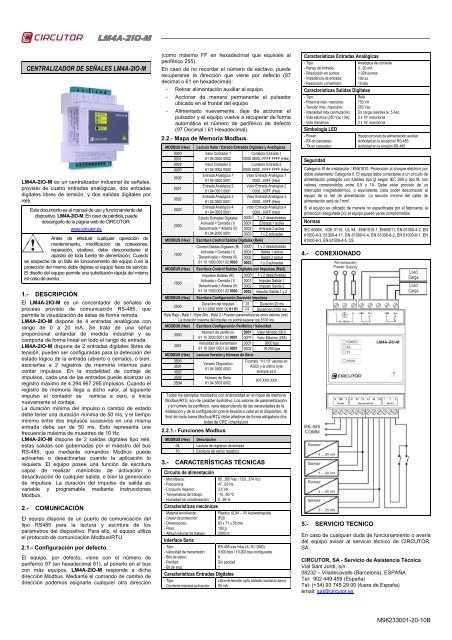
<strong>LM4A</strong>4A-<strong>2IO</strong><strong>2IO</strong>-MCENTRALIZADOR DE SEÑALES <strong>LM4A</strong>-<strong>2IO</strong>-M<strong>LM4A</strong>-<strong>2IO</strong>-M es un centralizador industrial de señales,provisto de cuatro entradas analógicas, dos entradasdigitales libres de tensión, y dos salidas digitales porrelé.Este documento es el manual de uso y funcionamiento deldispositivo <strong>LM4A</strong>-<strong>2IO</strong>-M. En caso de pérdida, puededescargarlo de la página web de CIRCUTOR:www.circutor.esAntes de efectuar cualquier operación demantenimiento, modificación de conexiones,reparación, etcétera, debe desconectarse elaparato de toda fuente de alimentación. Cuandose sospeche de un fallo de funcionamiento del equipo ó en laprotección del mismo debe dejarse el equipo fuera de servicio.El diseño del equipo permite una substitución rápida del mismoen caso de avería.1.- DESCRIPCIÓNEl <strong>LM4A</strong>-<strong>2IO</strong>-M es un concentador de señales deproceso provisto de comunicación RS-485, quepermite la visualización de éstas de forma remota.<strong>LM4A</strong>-<strong>2IO</strong>-M dispone de 4 entradas analógicas conrango de 0 a 20 mA. Se trata de una señalproporcional entándar de medida industrial y secomporta de forma lineal en todo el rango de entrada.<strong>LM4A</strong>-<strong>2IO</strong>-M dispone de 2 entradas digitales libres detensión; pueden ser configuradas para la detección delestado lógico de la entrada (abierto o cerrado), o bien,asociarlas a 2 registros de memoria internos paracontar impulsos. En la modalidad de contaje deimpulsos, cada una de las entradas puede alcanzar unregistro máximo de 4.294.967.295 implusos. Cuando elregistro de memoria llega a dicho valor, al siguienteimpulso el contador se reinicia a cero, e inicianuevamente el contaje.La duración mínima del impulso o cambio de estadodebe tener una duración mínima de 50 ms, y el tiempomínimo entre dos implusos sucesivos en una mismaentrada debe ser de 50 ms. Esto representa unafrecuencia máxima de muestreo de 10 Hz.<strong>LM4A</strong>-<strong>2IO</strong>-M dispone de 2 salidas digitales tipo relé;estas salidas son gobernadas por el maestro del busRS-485, que mediante comandos Modbus puedeactivarlas o desactivarlas cuando la aplicación lorequiera. El equipo posee una función de escrituracapaz de realizar maniobras de activación odesactivación de cualquier salida, o bien la generaciónde impulsos. La duración del impulso de salida esvariable y programable mediante instruccionesModbus.2.- COMUNICACIÓNEl equipo dispone de un puerto de comunicación deltipo RS485 para la lectura y escritura de losparámetros del dispositivo. Para ello, el equipo utilizael protocolo de comunicación Modbus/RTU.2.1.- Configuración por defecto.El equipo, por defecto, viene con el número deperiférico 97 (en hexadecimal 61), al ponerlo en el buscon más equipos, <strong>LM4A</strong>-<strong>2IO</strong>-M responde a dichadirección Modbus. Mediante el comando de cambio dedirección podemos asignarle cualquier otra dirección(como máximo FF en hexadecimal que equivale alperiférico 255).En caso de no recordar el número de esclavo, puederecuperarse la dirección que viene por defecto (97decimal o 61 en hexadecimal):- Retirar alimentación auxiliar al equipo- Accionar de manera permanente el pulsadorubicado en el frontal del equipo- Alimentado nuevamente, deje de accionar elpulsador y el equipo vuelve a recuperar de formaautomática el número de periférico de defecto(97 Decimal / 61 Hexadecimal).2.2.- Mapa de Memoria Modbus.MODBUS (Hex)000000010002000305000501050205032000MODBUS (Hex)1000Lectura Valor / Estado Entradas Digitales y AnalógicasValor Contador 1Contador Entrada 161 04 0000 0002 0000 0000...FFFF FFFF (Hex)Valor Contador 2Contador Entrada 261 04 0002 0002 0000 0000...FFFF FFFF (Hex)Entrada Analógica 1 Valor Entrada Analógica 161 04 0500 00010000...03FF (Hex)Entrada Analógica 2 Valor Entrada Analógica 261 04 0501 00010000...03FF (Hex)Entrada Analógica 3 Valor Entrada Analógica 361 04 0502 00010000...03FF (Hex)Entrada Analógica 4 Valor Entrada Analógica 461 04 0503 00010000...03FF (Hex)Estado Entradas Digitales 0000 1 y 2 desactivadasActivada = Cerrada (1) 0001 Entrada 1 activaDesactivada = Abierta (0) 0002 Entrada 2 activa61 04 2000 0001 0003 1 y 2 activadasEscritura Control Salidas Digitales (Relé)Control Salidas Digitales (R) 0000 1 y 2 desactivadasActivada = Cerrada (1) 0001 Salida 1 activaDesactivada = Abierta (0) 0002 Salida 2 activa61 10 1000 0001 02 0003 0003 1 y 2 activadasEscritura Control Salidas Digitales por Impulsos (Relé)MODBUS (Hex)Impulsos Salidas (R) 0000 1 y 2 desactivadas1500Activada = Cerrada (1) 0001 Impulso Salida 1Desactivada = Abierta (0) 0002 Impulso Salida 261 10 1500 0001 02 0003 0003 Impulso Salida 1 y 2MODBUS (Hex) Escritura Configuración Duración Impulsos2500Duración del Impulso 01 Duración 20 ms61 10 2500 0001 02 01 01 FF Duranción 5100 msByte Bajo - Relé 1 / Byte Alto - Relé 2 / Pueden parametrizarse otros valores (ms)La duración máxima del impulso no podrá superar los 5100 msMODBUS (Hex) Escritura Configuración Periférico / Velocidad3000Número de periférico 0001 Valor Mínimo (001)61 10 3000 0001 02 0001 00FF Valor Máximo (255)3001Velocidad de transmisión 0001 9600 bps61 10 3001 0001 02 0001 0002 19.200 bpsMODBUS (Hex) Lectura Versión y Número de Serie35003501350235033504Versión Dispositivo61 04 3500 0003Número de Serie61 04 3503 0002Formato: “V1.10” valores enASCII y el último bytesiempre es 0907 XXX XXXTodos los ejemplos mostrados con anterioridad en el mapa de memoriaModbus/RTU, son de carácter ilustrativo. Los valores de parametrizacióny el número de periférico, varia dependiendo de las necesidades de lainstalación y de la configuracón previa llevada a cabo en el dispositivo. Alfinal de cada trama Modbus/RTU debe añadirse de forma obligatoria dosbytes de CRC (checksum)2.2.1.- Funciones ModbusMODBUS (Hex) Descripción04 Lectura de registros de entrada10 Escritura de varios registros3.- CARACTERÍSTICAS TÉCNICASCircuito de alimentación- Monofásica:85...265 Vac / 120...374 Vcc- Frecuencia:47...63 Hz- Consumo máximo:3,5 VA- Temperatura de trabajo: -10...60 ºC- Humedad sin condensación: 5...95 %Características mecánicas- Material envolvente:- Grado de protección:- Dimensiones:- Peso:- Altitud máxima de trabajo:Interface Serie- Tipo:- Velocidad de transmisión:- Bits de datos:- Paridad:- Bit de stop:Características Entradas Digitales- Tipo:- Corriente máxima activación:Plástico UL94 – V0 AutoextinguibleIP2093 x 71 x 58 mm180 g2000 mRS-485 tres hilos (A / B / GND)9.600 bps / 19.200 bps configurable8Sin paridad1Libre de tensión opto aislada (contacto seco)50 mACaracterísticas Entradas Analógicas- Tipo:- Rango de entrada:- Resolución en puntos:- Impedancia de entrada:- Resolución convertidor:Características Salidas Digitales- Tipo:- Potencia máx. maniobra:- Tensión máx. maniobra:- Intensidad máx.conmutación:- Vida eléctrica (250 Vac / 5A):- Vida mecánicaSimbología LED- Power:- RX en parpadeo:- TX en parpadeo:SeguridadAnalógica de corriente0...20 mA1.024 puntos100 Ω10 bitsRelé750 VA250 VacEn carga resistiva Ie: 5 Aac3 x 10 4 maniobras2 x 10 7 maniobrasEquipo provisto de alimentación auxiliarActividad en la recepción RS-485Actividad en la emisión RS-485Categoría III de instalación / EN61010. Protección al choque eléctrico pordoble aislamiento Categoría II. El equipo debe conectarse a un circuito dealimentación protegido con fusibles tipo gl según IEC 269 o tipo M, convalores comprendidos entre 0,5 y 1A. Debe estar provisto de uninterruptor magnetotérmico, o equivalente, para poder desconectar elequipo de la red de alimentación. La sección mínima del cable dealimentación será de 1mm 2 .Si el equipo es utilizado de manera no especificada por el fabricante, laprotección asegurada por el equipo puede verse comprometida.NormasIEC 60664, VDE 0110, UL 94, EN61010-1, EN55011, EN 61000-4-2, EN61000-4-3, 61000-4-11, EN 61000-6-4, EN 61000-6-2, EN 61000-6-1, EN61000-6-3, EN 61000-4-5, CE4.- CONEXIONADO5.- SERVICIO TECNICOEn caso de cualquier duda de funcionamiento o averíadel equipo avisar al servicio técnico de CIRCUTOR,SA.CIRCUTOR, SA - Servicio de Asistencia TécnicaVial Sant Jordi, s/n08232 – Viladecavalls (Barcelona), ESPAÑATel: 902 449 459 (España)Tel: (+34) 93 745 29 00 (fuera de España)email: sat@circutor.esM98233001-20-10B
<strong>LM4A</strong>-<strong>2IO</strong><strong>2IO</strong>-M<strong>LM4A</strong>-<strong>2IO</strong>-M SIGNAL CENTRALIZER<strong>LM4A</strong>-<strong>2IO</strong>-M is an industrial signal centraliser with fouranalogue inputs, two voltage-free digital inputs and twodigital relay outputs.This document is the use and operation manual of the <strong>LM4A</strong>-<strong>2IO</strong>-M device. You can download the manual fromCIRCUTOR's web site in case it is misplaced:www.circutor.esYou must disconnect the unit from the powersupply before performing any maintenanceoperations, connection modifications, repairs, etc.If you suspect an operational fault in the unit or inits protection system, remove the unit from service. The designof the unit makes it easy to replace in the event of a fault.1.- DESCRIPTIONThe <strong>LM4A</strong>-<strong>2IO</strong>-M unit is a process signal concentratorthat uses RS-485 communication and allows forremote signal display.Likewise, the <strong>LM4A</strong>-<strong>2IO</strong>-M unit has 4 analogue inputsthat operate in the 0 to 20 mA range. The unit handlesstandard proportional industrial measurement signalsand operates in linear form throughout the input range.The <strong>LM4A</strong>-<strong>2IO</strong>-M unit also has 2 voltage-free digitalinputs; they can be configured to detect logical inputstate (open or closed) or associated to 2 internalmemory registers to count the impulses. In the impulsecounting mode, each input can record a maximum of4,294,967,295 impulses. When the memory recordreaches the maximum, the meter resets to zero withthe next impulse, starting the counting process again.The minimum duration of the impulse or change ofstate must be 50 ms and the minimum period of timebetween two subsequent impulses on the same inputmust be 50 ms. This represents a maximum samplingfrequency of 10 Hz.The <strong>LM4A</strong>-<strong>2IO</strong>-M unit has 2 digital relay outputs; theseoutputs are governed by the RS-485 bus master, whichcan activate or deactivate them with Modbuscommands when requested by the application. The unithas a write function that can perform activation ordeactivation operations on any output or generateimpulses. The duration of the output impulse is variableand it can be programmed with Modbus instructions.2.- COMMUNICATIONThe unit has an RS-485 communications port to readand write the device's parameters. To do so, the unituses the Modbus/RTU communications protocol.2.1.- Default configuration.The unit comes with peripheral number 97 by default(61 in hexadecimal). When placed on the bus withother equipment, <strong>LM4A</strong>-<strong>2IO</strong>-M responds to thisModbus address. The address modification commandcan be used to assign any other address (a maximumof FF in hexadecimal, equivalent to peripheral 255).In case the slave number is not known, the defaultaddress can be retrieved (97 in decimal or 61 inhexadecimal):- Disconnect the unit's auxiliary power supply- Permanently activate the button located on theunit's front panel- Power the unit while the button is activated andthe unit will automatically retrieve the defaultperipheral number (97 in decimal or 61 inhexadecimal).2.2.- Modbus memory map.MODBUS (Hex)000000010002000305000501050205032000MODBUS (Hex)1000Digital and Analogue Inputs Value / State ReadingMeter Value 1Meter Input 161 04 0000 0002 0000 0000...FFFF FFFF (Hex)Meter Value 2Meter Input 261 04 0002 0002 0000 0000...FFFF FFFF (Hex)Analogue input 1 Analogue input Value 161 04 0500 00010000...03FF (Hex)Analogue input 2 Analogue input Value 261 04 0501 00010000...03FF (Hex)Analogue input 3 Analogue input Value 361 04 0502 00010000...03FF (Hex)Analogue input 4 Analogue input Value 461 04 0503 00010000...03FF (Hex)Digital Input State 0000 1 and 2 deactivatedActivated = Closed (1) 0001 Input 1 activatedDeactivated = Open (0) 0002 Input 2 activated61 04 2000 0001 0003 1 and 2 activatedDigital Output Control Writing (Relay)Digital output Control (R) 0000 1 and 2 deactivatedActivated = Closed (1) 0001 Output 1 activatedDeactivated = Open (0) 0002 Output 2 activated61 10 1000 0001 02 0003 0003 1 and 2 activatedMODBUS (Hex) Impulse Digital Output Control Writing (Relay)Output Impulses (R) 0000 1 and 2 deactivated1500Activated = Closed (1) 0001 Output Impulse 1Deactivated = Open (0) 0002 Output Impulse 261 10 1500 0001 02 0003 0003 Output Impulse 1 & 2MODBUS (Hex) Impulse Duration Configuration Write2500Impulse duration 01 Duration 20 ms61 10 2500 0001 02 01 01 FF Duration 5100 msLow Byte - Relay 1 / High Byte - Relay 2 / Other values can be established (ms)The maximum duration of the impulse cannot exceed 5100 msMODBUS (Hex) Peripheral Configuration / Speed Writing3000Peripheral number 0001 Minimum value (001)61 10 3000 0001 02 0001 00FF Maximum (255)3001Transmission speed 0001 9600 bps61 10 3001 0001 02 0001 0002 19.200 bpsMODBUS (Hex) Version and Serial Number Reading35003501350235033504Device Version61 04 3500 0003Serial number61 04 3503 0002Format: “V1.10” values inASCII and the last byte isalways 0907 XXX XXXAll examples shown above on the Modbus/RTU memory map are providedfor information purposes only. The parameterisation values and peripheralnumber will vary, depending on the installation requirements and the priorconfiguration of the device. Two CRC bytes (checksum) must be added atthe end of each Modbus/RTU frame.2.2.1.- Modbus functionsMODBUS (Hex) Description04 Input records reading10 Writing of several records3.- TECHNICAL SPECIFICATIONSPower circuit- Single-phase:- Frequency:- Maximum consumption:- Working temperature:- Humidity withoutcondensation:Construction features- Enclosure material:- Protection degree:- Dimensions:- Weight:- Maximum operating height:Serial Interface- Type:- Transmission speed:- Data bits:- Parity:- Stop bit:85...265 Vac / 120...374 Vdc47...63 Hz3.5 VA-10...60 ºC5...95 %UL94 – V0 Self-extinguishing PlasticIP2093 x 71 x 58 mm180 g2000 mThree-wire RS-485 (A / B / GND)9,600 bps / 19,200 bps configurable8No parity1Digital Input Characteristics- Type:Voltage-free opto-insulated (dry contact)- Maximum activation current: 50 mAAnalogue Input Characteristics- Type:- Input range:- Resolution in points:- Input impedance:- Transducer resolution:Analogue current0...20 mA1.024 points100 Ω10 bitsDigital Output Characteristics- Type:- Max. operating power:- Max. operating voltage:- Max. switching current:- Electrical life (250 Vac / 5A):- Mechanical lifeLED symbols- Power:- Flashing RX:- Flashing TX:SafetyRelay750 VA250 VacWith resistive load Ie: 5 Aac3 x 10 4 operations2 x 10 7 operationsEquipment with auxiliary power supplyRS-485 Reception activityRS-485 Emission activityInstallation Category III / EN61010. Double-insulated electric shockprotection Category II. The equipment must be connected to a powercircuit protected with type gl fuses, in compliance with IEC 269, or type M,with values from 0.5 to 1A. It must be fitted with a circuit breaker switch oran equivalent device, in order to be able to disconnect the equipment fromthe power supply grid. The minimum diameter of the power supply cableshall be 1mm 2 .If the unit is not operated according to the manufacturer's specifications,the equipment guaranteed degree of protection may be compromised.StandardsIEC 60664, VDE 0110, UL 94, EN61010-1, EN55011, EN 61000-4-2, EN61000-4-3, 61000-4-11, EN 61000-6-4, EN 61000-6-2, EN 61000-6-1, EN61000-6-3, EN 61000-4-5, CE4.- CONNECTIONS5.- TECHNICAL SERVICEIf you have any doubts about the operation of the unitor suspect any malfunction, contact our service staff atCIRCUTOR, SACIRCUTOR, SA - Technical AssistenceVial Sant Jordi, s/n08232 – Viladecavalls (Barcelona), SPAINTel: (+34) 93 745 29 00email: sat@circutor.esM98233001-20-10B
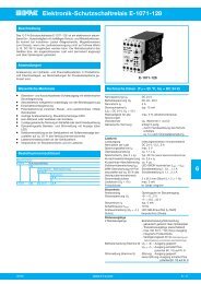
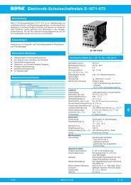
Electrical energy meters for partial consumptionCentralizador 4 entradasLM 4A-<strong>2IO</strong> MImpulse CENTRALIZING UNITAnalogue and digitalsignals centralizerDescriptionFeaturesThe <strong>LM4A</strong>-<strong>2IO</strong>-M is an analogue and digitalsignals centralizer. In only 4 DIN modules,the unit has 2 relay outpus and centralizes 4analogue inputs from 0 ... 20 mA, 2 voltagefreedigital input. The unit includes an RS-485 communications bus with a Modbus/RTU protocol, which allows real time controlby communications. The unit is compatiblewith PowerStudio and PowerStudio SCA-DA control software.Other features:}}Telemanagement of the 2 digital outputs}}Supervision of the 2 digital inputs}}Monitoring of the 4 analogue inputsApplication}}Reading any Impulse-emitting device (upto 4 units). These parameters are useful togenerate receipts or define a price/unit cost}}Alarm central: the unit’s outputs can acton contacts, sound and/or luminous devicesto carry out a protection or warning operationwith an internal relay.Power supply circuitConsumptionFrequencyDigital InputsMax. activation currentAnalogue Inputs 4Input rangeTransducer resolutionDigital outputs (relay)Max. operating powerMax. operating voltageMax. switching currentElectrical working life (250 Vc.a. / 5 A)Mechanical working life85 ... 265 Va.c. / 120 ... 374 Vd.c.4,6 ... 7,5 V·A47...63 Hz2 (opto-insulated voltage-free)20 mA0 ... 20 mA10 bits (1024 points)4 (5 A max.)750 V·A250 Va.c.Resistive load I: 5 Aa.c.3 x 10 4 operations2 x 10 7 operationsEnvironmental conditionsOperating temperature -10 ... +60 ºCHumedad relativa (sin condensación) 5 ... 95%Características constructivasTipo de cajaPlástico UL94-V0 autoextinguibleCommunicationsPortRS-485ProtocolModbusProtection degree IP 20Dimensions93 x 71 x 58 mm (4 DIN Rail modules)SafetyEN 61010 double-insulated electric shock protection class IIStandardsIEC60664, VDE0110, UL94, EN61010-1, EN55011, EN61000-4-3,EN61000-4-11,EN61000-6-4, EN61000-4-2, EN61000-6-2, EN61000-6-2,EN61000-6-1, EN61000-6-3, EN61000-4-5M3-26
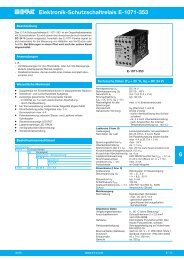
Electrical energy meters for partial consumptionCentralizador 4 entradasLM 4A-<strong>2IO</strong>-MImpulse CENTRALIZING UNITAnalogue and digitalsignals centralizerReferencesDigitalinputsAnalogueinputs2 4 4DigitaloutputsCommunicationprotocolMODBUS (RTU) DIN modules Type CodeRS-485 (9600 - 19200bps, 7/8, none,even, odd, 1/2)4 LM 4A-<strong>2IO</strong>-M M31565DimensionsConnectionsM3-27