Leistungsschutzschalter thermisch 482-... 4
Leistungsschutzschalter thermisch 482-... 4
Leistungsschutzschalter thermisch 482-... 4

You also want an ePaper? Increase the reach of your titles
YUMPU automatically turns print PDFs into web optimized ePapers that Google loves.
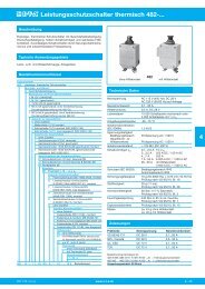
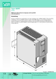
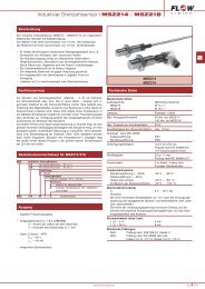
<strong>Leistungsschutzschalter</strong> <strong>thermisch</strong> <strong>482</strong>-...BeschreibungEinpoliger, <strong>thermisch</strong>er Schutzschalter mit Gewindehalsbefestigung,Druck/Zug-Betätigung, hohem Schaltvermögen und wahlweise Hilfs -kontakten. Zuverlässiges Schaltverhalten durch Sprungschaltme chanismus und unbeeinflussbare Freiauslösung.Typische AnwendungsgebieteLand-, Luft- und Wasserfahrzeuge, AnlagenbauBestellnummernschlüsselTypennummer<strong>482</strong> einpoliger, <strong>thermisch</strong>er SchutzschalterMontage- und BauartG GewindehalsbefestigungAbmessung und Form (Gewindehals)1 M 12x1 (vernickelt)2 M 12x1 (geschwärzt)3 15/32-UN-2A (geschwärzt)6 M12x1x8 (geschwärzt), ohne Verdrehsicherung,Druckknopfbeschriftung wie <strong>482</strong>-G2..7 M12x1x6,4 (geschwärzt), ohne Verdrehsicherung,Druckknopfbeschriftung wie bei <strong>482</strong>-G1..Zubehör für Gewindehals0 ohne Zubehör1 Wellscheibe 12/15 montiert2 Zahnscheibe 12/15 montiert (MS 35333-136)3 Zahnscheibe 12/15 lose beigepackt (MS 35333-136)Zubehör für Gewindehals0 ohne Zubehör1 Sechskantmutter M12x1 vernickelt2 Sechskantmutter M12x1 geschwärzt3 Sechskantmutter 15/32-32UN-2B (geschwärzt) montiert4 Sechskantmutter 15/32-32UN-2B, (geschwärzt) losebeigepackt (MS 25082-B21)Anschlussform der HauptanschlüsseK1 Schraubklemmen mit metr. Gewinde M4J1 Schraubklemmen mit Zoll-Gewinde 8-32UNC-2BR1 Rundstecker ø6KennlinieM1 Thermisch 1,15 - 1,4 x I NZubehör KlemmschraubenA Flachkopfschraube (ISO 1580) M4x6, montiertB Linsenschraube mit Kreuzschlitz8-32UNC-2Ax6 (MS51957-41), montiertF Linsenschraube mit KreuzschlitzM4x6 (ISO 7045), lose beigepacktH Zylinderschraube mit InnensechskantM4x6 (DIN 7984), montiertK Sechskantschraube mit Kreuzschlitz8-32UNC-3Ax7,6, montiertZ ohne ZubehörZubehör Klemmscheiben0 ohne Zubehör1 Federscheibe DIN 137-B4, montiert2 Federring 4,3 montiert, MS 35338-1373 Federring 4,3 lose beigepackt (MS 35338-137)5 Federscheibe 4,3/9, montiert6 Federscheibe DIN 137-B4, lose beigepacktHilfskontaktS0 ohne HilfskontaktS1 mit Hilfskontakt Öffner (Steckbuchsefür Steckerstift nach EN 3155-016M2018)S5 wie S1, jedoch gepoltTrennwand. ohne Trennwand (Standard)T mit Trennwand 31 breitNennstrombereich0,1...50 A<strong>482</strong> - G 1 1 1 - K1 M1 - A 1 S1 . - 10 A Bestellbeispielohne HilfskontaktTechnische Daten<strong>482</strong>mit HilfskontaktNennspannungAC 115 V (400 Hz); DC 28 VAC 230 V (50/60 Hz) auf AnfrageNennstrombereich 0,1...50 AHilfsstromkreis0,5 A, DC 28 VLebensdauer10 000 Schaltspiele mechanisch oder5 000 Schaltspiele mit 1 x I NUmgebungstemperatur -55...75 °CIsolationskoordination(IEC 60664)1,5 kV/3SpannungsfestigkeitBetätigungsbereich Prüfspannung AC 1 500 VHauptstrom- zuHilfsstromkreis Prüfspannung AC 1 500 VIsolationswiderstand > 100 MΩ (DC 500 V)Schaltvermögen I cn 0,1...2,5 A 15 x I N3...3,5 A 250 A DC / 150 A AC4...7 A 500 A7,5...50 A 6 000 A DC / 1 000 A AC35...50 A mit Hilfskontakt:3 000 A DC / 1 000 A ACSchutzart (IEC 60529) Betätigungsbereich IP40Anschlussbereich IP00Schwingungsfestigkeit 10 g (55-2000 Hz), ± 0,76 mm (10-55 Hz)Prüfung nach VG 95210, Bl. 19Stoßfestigkeit50 g (11 ms),Prüfung nach VG 95210, Bl. 28Korrosionsfestigkeit 48 Std. in 5 % Salznebel,Prüfung nach VG 95210, Bl. 2Feuchtigkeitsprüfung 240 Std. in 95 % rel. Feuchte,Prüfung nach VG 95210, Bl. 7Explosionsdichtheit Prüfung nach VG 95210, Bl. 10Masseca. 43 g ohne Hilfskontaktca. 46 g mit HilfskontaktZulassungenPrüfstelle Nennspannung NennstrombereichVG 95345 T21 DC 28 V 0,1...50 AQPL, Canada DC 28 V 0,5...35 AUL, CSA DC 72 V 0,1...50 ATÜV DC 72 V 0,1...50 ABestellnummernschlüssel alt:<strong>482</strong>-N-MS (<strong>482</strong>-G111-K1M1-A1S0-...A) = Fahrzeugschutzschalter<strong>482</strong>-MS (<strong>482</strong>-G212-K1M1-A1S0-...A) = LuftfahrtschutzschalterVerpackungseinheit: 50 Stück42011/12 (101210)www.e-t-a.de 4 - 39
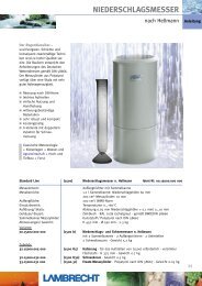
<strong>Leistungsschutzschalter</strong> <strong>thermisch</strong> <strong>482</strong>-...4Nennströme und typische SpannungsfälleNenn- Spannungsfall Nenn- Spannungsfallstrom (A) (mV) strom (A) (mV)0,1 16 000 5 3500,2 8 000 7,5 2300,5 3 000 10 < 2000,8 2 000 15 < 2001 1 500 20 < 2001,2 1 200 25 < 2001,5 1 000 30 < 2001,8 850 35 < 2002 800 40 < 2002,5 700 45 < 2003 600 50 < 2004 430Maßbilder <strong>482</strong>-G1<strong>482</strong>-G111-K1M1-A1S0 (VG 95345 T21)12,2 AUSEIN6max. 50Anzugsdrehmoment max. 4 NmM12x1 ø10,61,56,3543,4max. 48min. 3ø8,4schwarzweißMaßbilder <strong>482</strong>-G2../-G6../-G7..<strong>482</strong>-G212-K1M1-A1S0 (VG 95345 T21)Anzugsdrehmoment max. 4 NmM12x112,2 AUSEIN<strong>482</strong>-G600-K1M1-A1S0Anzugsdrehmoment max. 4 NmM12x110,7 AUS4,5 EIN6max. 50Verdrehsicherung182,71,5max. 2,5Anschlussschraube ISO1580-M4x617,9mit Federscheibe DIN 137 B4Anzugsdrehmoment max. 1,2 NmNennstrom in AEinbaulöcher59,50,83145°6,3543,4max. 48min. 3ø12,5 +0,21,5 - 3 dick3,5ø10,6min. ø3,2ø10,6ø8,4schwarzweißø8,4schwarzweißFederscheibeFederscheibeFederscheibe9,5 ±0,2ø8,4schwarzweißmax. 2,5VerdrehsicherungAnschlussschraube ISO1580-M4x617,9mit Federscheibe DIN 137 B4Anzugsdrehmoment max. 1,2 NmNennstrom in AEinbaulöcher45°12,2 AUSEIN68 -0,4max. 5043,4max. 48max. 2,5max. 5018716,22,7Anzugsdrehmoment max. 4 NmM12x1 ø10,61,5max. 2,559,50,8316,3543,4max. 48ø12,5 +0,21,5 - 3 dick<strong>482</strong>-G111-K1M1-A1S1 (VG 95345 T21)<strong>482</strong>-G111-K1M1-A1S5min. ø3,2min. 39,5 ±0,214,522°<strong>482</strong>-G700-R1M1-Z0S012,2 AUSEIN618max. 6,3517,95max. 3145°Anzugsdrehmoment max. 4 NmM12x1Anschlussschraube ISO1580-M4x6mit Federscheibe DIN 137 B4Anzugsdrehmoment max. 1,2 NmEinbaulochNennstrom in A42,2ø12,5 +0,21,5 - 3 dickmin. 3ø10,6ø8,4schwarzweißschwarzVerdrehsicherungAnschlussschraube ISO1580-M4x617,9mit Federscheibe DIN 137 B4Anzugsdrehmoment max. 1,2 NmNennstrom in AEinbaulöcher45°19,618max. 10,52,7HilfskontaktSteckbuchse fürSteckerstift nachEN 3155-016M2018max. 6,559,50,8max. 31ø12,5 +0,21,5 - 3 dickmin. ø3,29,5 ±0,2max. 19225max. 31Nennstrom in Aø12,5 +0,21,5 - 3 dickEinbaulochø64 - 40www.e-t-a.de2011/12 (101210)
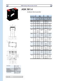
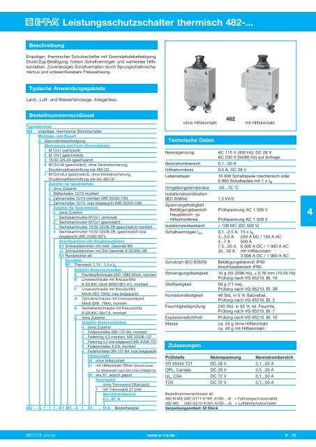
12,7<strong>Leistungsschutzschalter</strong> <strong>thermisch</strong> <strong>482</strong>-...Maßbilder <strong>482</strong>-G3...Zeit/Strom-Kennlinien<strong>482</strong>-G323-J1M1-B2 (MS 25 244)(Gesamtabschaltzeit bei Nennspannung)AUS 19,05 max.max. 50 EIN 11,95 min.1,5Anzugsdrehmoment max. 4 Nm ø10,615/32-32-UNS-2A THD43,46,35max. 47,3min. 3ø8,4schwarzweißSechskantmutterMS 25082-B21ZahnscheibeMS 35333-1360,1…2,5 ASchaltzeit in Sekunden10000100010010175 °C23 °C-55 °Cmax. 2,50,117,945°Anschlussschraube MS 51957-418-32UNC-2A)mit Federscheibe MS 35338-137Anzugsdrehmoment max. 1,2 Nm0,01VerdrehsicherungNennstrom in AEinbaulöchermin. ø3,2 1,5 - 3 dick0,0011 2 4 6 8 10 20 40 6080100Vielfache des Nennstromes2,73…50 A1850,831<strong>482</strong>-G323-J2..-E3S0T9,59,5 ±0,2ø12,5 +0,2Schaltzeit in Sekunden10000100010010175 °C23 °C-55 °C4Anzugsdrehmoment max. 4 Nm15/32-32UNS-2Aø10,6ø8,40,112,2AUS6EIN1,56,35min. 3schwarzweißSechskantmutterMS 25082-B21Federscheibe0,010,0011 2 4 6 810 20 40 6080100Vielfache des Nennstromes52min. 6,619,33144,145°Trennwand0,8Anschlussschraube NAS 1801-08-7Federscheibe MS 35338-137Anzugsdrehmoment max. 1,2 NmSchaltbilderohne HilfskontaktNetz 1Verdrehsicherungmax. 19Nennstrom in A5max. 319,5Einbaulöchermin. ø3,21,5 - 3 dick9,5 ±0,2ø12,5 +0,22mit HilfskontaktNetz 111mit gepoltem HilfskontaktNetz 13212252011/12 (101210)www.e-t-a.de 4 - 41
<strong>Leistungsschutzschalter</strong> <strong>thermisch</strong> <strong>482</strong>-...ZubehörSchutzkappe mit Sechskantmutter und O-Ring(IP66 und IP67)Best.-Nr. X 200 801 08 (Mutter M12x1 vernickelt,Schutzkappe transparent)Best.-Nr. X 200 801 03 (Mutter M12x1 geschwärzt,Schutzkappe schwarz)Kennzeichnungsring zum Aufschnappen auf den DruckknopfBest.-Nr. Y 307 004 01 schwarzY 307 004 02 weißY 307 004 03 rotY 307 004 04 grünY 307 004 05 blauø14ø6,856,4ø12,35M12x1Schutzkappe mit Sechskantmutter (IP54)Best.-Nr. X 200 802 01 (Mutter M12x1, vernickelt)Best.-Nr. X 200 802 02 (Mutter M12x1, geschwärzt)0,65M12x1Sperrring zum Blockieren des Druckknopfes in AUS-StellungBest.-Nr. Y 307 005 01 rotBest.-Nr. Y 307 005 02 schwarz4Aufsatzbetätigungsknopf (schwarz)zum Aufklemmen auf den DruckknopfBest.-Nr. X 200 803 01ø20177,7ø14,6ø10,9Die zur Verfügung gestellten Informationen sind nach unserem Wissen genau und zuverlässig,jedoch übernimmt E-T-A keine Verantwortung für den Einsatz in einer Anwendung,die nicht der vorliegenden Spezifikation entspricht. E-T-A behält sich das Recht vor,Spezifikationen im Sinne des technischen Fortschritts jederzeit zu ändern. Maßänderungensind vorbehalten, bei Bedarf bitte neuestes Maßblatt mit Toleranzen anfordern. Maße,Daten, Abbildungen und Beschreibung entsprechen dem neuesten Stand bei Herausgabedieses Kataloges, sind aber unverbindlich! Änderungen sowie auch Irrtümer und Druckfehlervorbehalten. Die Bestellbezeichnung der Geräte kann von deren Beschriftung abweichen.4 - 42www.e-t-a.de2011/12 (101210)
High Performance Thermal Circuit Breaker <strong>482</strong>-...DescriptionSingle pole compact high performance thermal circuit breaker withtease-free, trip-free, snap action mechanism and push/pull on/offmanual actuation (M-type TO CBE to EN 60934). An indicator bandon the push button clearly shows the tripped/off position. Threadneckpanel mounted in tracked vehicle and aircraft/general purpose versions,with optional auxiliary contacts.Typical applicationsExtra low voltage wiring systems on all types of vehicles for land, seaand air, battery powered machines, process control.Ordering informationType No.<strong>482</strong> single pole thermal circuit breakerMountingG threadneck panel mountingThreadneck design1 M 12x1 nickel plated2 M 12x1 black3 15/32-UN-2A black6 M12x1x8 black, without locating pin,push button marking as with <strong>482</strong>-G2..7 M12x1x6,4 black, without locating pin,push button marking as with <strong>482</strong>-G1..Hardware - washer for threadneck0 without hardware1 corrugated washer 12/15, fitted2 serrated lock washer 12/15, fitted (MS 35333-136)3 serrated lock washer 12/15, bulk shipped (MS 35333-136)Hardware - hex nut for threadneck0 without hardware1 hex nut M12x1 nickel plated2 hex nut M12x1 black3 hex nut 15/32-UN-2B black, fitted4 hex nut 15/32-UN-2B black, bulk shippedTerminal design (main terminals)K1 screw terminals with metric thread M4J1 screw terminals with inch thread 8-32-UNC-2BR1 round connector ø6Characteristic curveM1 thermal 1.15-1.4 I NTerminal screwsA flat head screw M4x6, ISO 1580, fittedB Phillips screw 8-32UNC-2Ax6(MS 51957-41), fittedF Phillips screw M4x6 (ISO 7045), bulk shippedH socket head cap screwM4x6 (DIN 7984), fittedK hex screw 8-32UNC-3Ax7.6 fittedZ withoutTerminal washers0 without lock washer1 lock washer DIN 137-B4, fitted2 lock washer 4.3, fitted, MS 35338-1373 lock washer 4.3, bulk shipped(MS 35338-137)5 lock washer 4.3/9, fitted6 lock washer DIN 137-B4, bulk shippedAuxiliary contactS0 without auxiliary contactsS1 with auxiliary contact (NC)S5 with polarized aux. contact (NC)Barrier(blank) without barrierT with barrier, 31 mm wideCurrent ratings0.1...50 A<strong>482</strong> - G 1 1 1 - K1 M1 - A 1 S1 . - 10 A ordering examplewithout aux. contactsTechnical data<strong>482</strong>with aux. contactsVoltage ratingAC 115 V (400 Hz); DC 28 VAC 230 (50/60 Hz) to special orderCurrent rating range 0.1...50 AAuxiliary circuit0.5 A, DC 28 VTypical life10,000 operations mechanical5,000 operations at I NAmbient temperature -55...+75 °C (-67...+167 °F)Insulation co-ordination rated impulse pollution(IEC 60664 and 60664A) withstand voltage degree1.5 kV 3Dielectric strength(IEC 60664 and 60664A) test voltageoperating area AC 1,500 Vmain to aux. circuit AC 1,500 VInsulation resistance > 100 MΩ (DC 500 V)Interrupting capacity I cn 0.1...2.5 A 15 x I N3...3.5 A 250 A DC / 150 A AC4...7 A 500 A7.5...50 A 6,000 A DC / 1,000 A AC35...50 A with auxiliary contact:3,000 A DC / 1,000 A ACInterrupting capacity I N U N(UL 1077) 0.1...50 A DC 72 V 5,000 ADegree of protection operating area IP40(IEC 60529/DIN 40050 terminal area IP00VibrationShockCorrosionHumidityExplosionMassPrevious ordering codes:<strong>482</strong>-N-MS = <strong>482</strong>-G111-K1M1-A1S0-...A<strong>482</strong>-MS = <strong>482</strong>-G212-K1M1-A1S0-...AApprovals10 g (55-2000 Hz), ± 0.76 mm (10-55 Hz)to VG 95210, sheet 19/IEC 60068-2-6, test Fc50 g (11 ms)to VG 95210, sheet 28/IEC 60068-2-27, test Ea48 hours at 5 % salt mistto VG 95210, sheet 2/IEC 60068-2-11, test Ka240 hours at 95 % RHto VG 95210, sheet 7/IEC 60068-2-3, test Cto VG 95210, sheet 10/MIL-STD-202,meth. 109approx. 43 g without auxiliary contactapprox. 46 g with auxiliary contactAuthority Voltage ratings Current ratingsVG 95345 T21 DC 28 V 0.1...50 AQPL, Canada DC 28 V 0.5...35 AUL, CSA DC 72 V 0.1...50 ATÜV DC 72 V 0.1...50 A4Issue C (101210) www.e-t-a.com4 - 39
12.7.500High Performance Thermal Circuit Breaker <strong>482</strong>-...Dimensions <strong>482</strong>-G3...Typical time/current characteristics<strong>482</strong>-G323-J1M1-B2 (MS 25 244)max. 19.05max .750min. 11.95min .470OFFONmax. 50max. 1.971.5.059tightening torque max. 4 Nm15/32-32-UNS-2A THDmax. 2.543.46.351.71.250max. 47.3max. 1.86min. 3min .118ø10.6.417ø8.4.331blackwhitehex nutMS 25082-B21lock washerMS 35333-1360.1...2.5 ATrip time in seconds1000010001001010.1+75 °C+167 °F+23 °C+73.4 °F-55 °C-67 °F12.2.480OFF18.7096ONmax .0982.7.106.236location pin0.8.03117.9.70459.5.37431max. 1.22<strong>482</strong>-G323-J2..-E3S0T45°current rating in Atightening torque max. 4 Nm15/32-32UNS-2A6.35.250Phillips screw MS 51957-41(8-32UNC-2A)with lock washer MS 35338-137tightening torque max. 1.2 Nmmin. ø3.2min .1269.5 ±0.2.374 ±.008min. 3min .118mounting holesø10.6.417ø8.4.331thickness1.5 - 3 mm.059 - .118 in.blackwhiteø12.5 +0.2.492 +.008hex nutMS 25082-B210.010.0013...50 A100001000Trip time in seconds1001010.10.010.0011 2 4 6 8 10 20 40 6080100… times rated current1 2 4 6 810 20 40 6080100… times rated current+75 °C+167 °F+23 °C+73.4 °F-55 °C-67 °F4522.05min 6.6min .2601.5.059location pin19.3.760311.2244.11.7445°current rating in Abarrier0.8.031lock washerterminal screw NAS 1801-08-7with lock washer MS 35338-137tightening torque max. 1.2 Nmmounting holesmin. ø3.2 thicknessmin .126 1.5 - 3 mm.059 - .118 in.Internal connection diagramsline 12max. 19max .74859.5.374max. 31max. 1.229.5 ±0.2.374 ±.008ø12.5 +0.2.492 +.008with auxiliary contactline 111with polarizedauxiliary contactline 1321225This is a metric design and millimeter dimensions take precedence ( mm )inchIssue C (101210) www.e-t-a.com4 - 41
High Performance Thermal Circuit Breaker <strong>482</strong>-...Accessories (approved to VG 95345, part 23)AccessoriesSplash cover /hex nut assembly with O ring (IP66 and IP67)X 200 801 08 nickel plated nut M12x1, transparent coverX 200 801 03 matt black finish nut M12x1, black coverIdentification collar to be snapped on the push buttonY 307 004 01 blackY 307 004 02 whiteY 307 004 03 redY 307 004 04 greenY 307 004 05 blueø14.551ø6.85.270M12x1Splash cover black /hex nut assembly with O ring (IP54)X 200 802 01 nickel plated nut M12x1X 200 802 02 matt black finish nut M12x16.4.252ø12.35.4864M12x1Actuator extension (black)to be fitted on the push buttonX 200 803 01ø20ø.78717.6690.65.026Lock out ring to block the push button in OFF positionY 307 005 01 redY 307 005 02 black7.7.303ø14.6.575ø10.9.4290.8.031This is a metric design and millimeter dimensions take precedence ( mm )inchAll dimensions without tolerances are for reference only. In the interest of improved design,performance and cost effectiveness the right to make changes in these specificationswithout notice is reserved.Product markings may not be exactly as the ordering codes.Errors and omissions excepted.4 - 42www.e-t-a.comIssue C (101210)