Elektronik-Schutzschaltrelais E-1071-353 6
Elektronik-Schutzschaltrelais E-1071-353 6
Elektronik-Schutzschaltrelais E-1071-353 6
- No tags were found...

You also want an ePaper? Increase the reach of your titles
YUMPU automatically turns print PDFs into web optimized ePapers that Google loves.
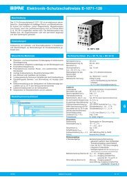
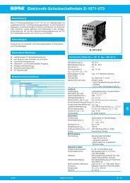
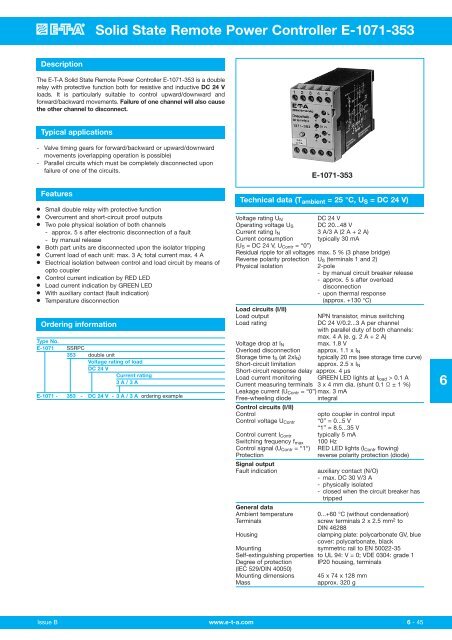
Solid State Remote Power Controller E-<strong>1071</strong>-<strong>353</strong>DescriptionThe E-T-A Solid State Remote Power Controller E-<strong>1071</strong>-<strong>353</strong> is a doublerelay with protective function both for resistive and inductive DC 24 Vloads. It is particularly suitable to control upward/downward andforward/backward movements. Failure of one channel will also causethe other channel to disconnect.Typical applications- Valve timing gears for forward/backward or upward/downwardmovements (overlapping operation is possible)- Parallel circuits which must be completely disconnected uponfailure of one of the circuits.Features● Small double relay with protective function● Overcurrent and short-circuit proof outputs● Two pole physical isolation of both channels- approx. 5 s after electronic disconnection of a fault- by manual release● Both part units are disconnected upon the isolator tripping● Current load of each unit: max. 3 A; total current max. 4 A● Electrical isolation between control and load circuit by means ofopto coupler● Control current indication by RED LED● Load current indication by GREEN LED● With auxiliary contact (fault indication)● Temperature disconnectionOrdering informationType No.E-<strong>1071</strong> SSRPC<strong>353</strong> double unitVoltage rating of loadDC 24 VCurrent rating3 A / 3 AE-<strong>1071</strong> - <strong>353</strong> - DC 24 V - 3 A / 3 A ordering exampleE-<strong>1071</strong>-<strong>353</strong>Technical data (T ambient = 25 °C, U S = DC 24 V)Voltage rating U NDC 24 VOperating voltage U S DC 20...48 VCurrent rating I N 3 A/3 A (2 A + 2 A)Current consumption typically 30 mA(U S = DC 24 V, U Contr = “0”)Residual ripple for all voltages max. 5 % (3 phase bridge)Reverse polarity protection U S (terminals 1 and 2)Physical isolation2-pole- by manual circuit breaker release- approx. 5 s after overloaddisconnection- upon thermal response(approx. +130 °C)Load circuits (I/II)Load outputNPN transistor, minus switchingLoad ratingDC 24 V/0.2...3 A per channelwith parallel duty of both channels:max. 4 A (e. g. 2 A + 2 A)Voltage drop at I Nmax. 1.8 VOverload disconnection approx. 1.1 x I NStorage time t S (at 2xI N ) typically 20 ms (see storage time curve)Short-circuit limitation approx. 2.5 x I NShort-circuit response delay approx. 4 μsLoad current monitoring GREEN LED lights at I load > 0.1 ACurrent measuring terminals 3 x 4 mm dia. (shunt 0.1 Ω ± 1 %)Leakage current (U Contr = “0”) max. 3 mAFree-wheeling diode integralControl circuits (I/II)Controlopto coupler in control inputControl voltage U Contr “0” = 0...5 V“1” = 8.5...35 VControl current I Contr typically 5 mASwitching frequency f max 100 HzControl signal (U Contr = “1“) RED LED lights (I Contr flowing)Protectionreverse polarity protection (diode)Signal outputFault indicationauxiliary contact (N/O)- max. DC 30 V/3 A- physically isolated- closed when the circuit breaker hastrippedGeneral dataAmbient temperature 0...+60 °C (without condensation)Terminalsscrew terminals 2 x 2.5 mm 2 toDIN 46288Housingclamping plate: polycarbonate GV, bluecover: polycarbonate, blackMounting symmetric rail to EN 50022-35Self-extinguishing properties to UL 94: V = 0; VDE 0304: grade 1Degree of protection IP20 housing, terminals(IEC 529/DIN 40050)Mounting dimensions 45 x 74 x 128 mmMassapprox. 320 g6Issue B www.e-t-a.com6 - 45