s6i_935_a00:Layout 1.qxd - Elvox.com
s6i_935_a00:Layout 1.qxd - Elvox.com
s6i_935_a00:Layout 1.qxd - Elvox.com

Create successful ePaper yourself
Turn your PDF publications into a flip-book with our unique Google optimized e-Paper software.
<strong>935</strong>A<strong>935</strong>AAVVERTENZE PER L'INSTALLATORE- Leggere attentamente le av ver ten ze contenute nelpre sen te do cu men to in quanto for ni sco no importantiindicazioni ri guar dan ti la sicurezza di in stal la zio ne,d'uso e di ma nu ten zio ne.- Dopo aver tolto l'imballaggio assicurarsi dell'integritàdel l'ap pa rec chio. Gli ele men ti dell'imballaggio (sacchettidi pla sti ca, po li sti ro lo espanso, ecc.) non devonoessere lasciati alla portata dei bambini inquanto potenziali fonti di pericolo. L'esecuzione dell'impiantodeve essere ri spon den te alle nor me CEIvigenti.- È necessario prevedere a monte dell'alimentazioneun appropriato in ter rut to re di tipo bipolare facilmenteaccessibile con separazione tra i contatti di almeno3mm.- Prima di col le ga re l'apparecchio ac cer tar si che i datidi targa siano rispondenti a quelli della rete di di stri -bu zio ne.- Questo ap pa rec chio dovrà essere de sti na to solo all'usoper il quale è stato espres sa men te concepito, ecioè per sistemi di citofonia o videocitofonia. Ognialtro uso è da con si de rar si im pro prio e quindi pericoloso.Il costruttore non può essere con si de ra to responsa bi le per even tua li danni derivanti da usiimpropri, erronei ed ir ra gio ne vo li.- Prima di ef fet tua re qual si a si operazione di pu li zia o dima nu ten zio ne, disinserire l'apparecchio dalla rete diali men ta zio ne elettrica, spe gnen do l'interruttore dell'impian to.- In caso di guasto e/o di cattivo fun zio na men to dell'appa rec chio, togliere l'ali men ta zio ne me dian te l'interruttoree non ma no met tere l’apparecchio. Perl'even tua le ri pa ra zio ne ri vol ger si so la men te ad uncentro di assistenza tecnica autorizzato dal costruttore.Il mancato ri spet to di quanto so pra può <strong>com</strong>promet te re la si cu rez za del l'ap pa rec chio.- Non ostru i re le aperture o fessure di ven ti la zio ne o dismaltimento calore e non esporre l’apparecchio a stillicidioo spruzzi d’acqua. Nessun oggetto pieno di liquido,quali vasi, deve essere posto sull’apparecchio.- L'installatore deve as si cu rar si che le in for ma zio ni perl'uten te siano pre sen ti sugli ap pa rec chi derivati.- Tutti gli apparecchi costituenti l'impianto devono esserede sti na ti esclu si va men te all'uso per cui sonostati con ce pi ti.- ATTENZIONE: per evitare di ferirsi, questo apparecchiodeve essere assicurato al pavimento/alla paretesecondo le istruzioni di installazione.- Questo do cu men to dovrà sem pre ri ma ne re allegatoalla do cu men ta zio ne dell'impianto.Direttiva 2002/96/CE (WEEE, RAEE).Il simbolo del cestino barrato riportato sull’apparecchioindica che il prodotto, alla fine dellapropria vita utile, dovendo essere trattato separatamentedai rifiuti domestici, deve essere conferito in uncentro di raccolta differenziata per apparecchiature elettricheed elettroniche oppure riconsegnato al rivenditoreal momento dell’acquisto di una nuovaapparecchiatura equivalente.L’utente è responsabile del conferimento dell’apparecchioa fine vita alle appropriate strutture di raccolta.L’adeguata raccolta differenziata per l’avvio successivodell’apparecchio dismesso al riciclaggio, al trattamentoe allo smaltimento ambientalmente <strong>com</strong>patibile contribuiscead evitare possibili effetti negativi sull’ambientee sulla salute e favorisce il riciclo dei materiali di cui è<strong>com</strong>posto il prodotto. Per informazioni più dettagliateinerenti i sistemi di raccolta disponibili, rivolgersi al serviziolocale di smaltimento rifiuti, o al negozio in cui èstato effettuato l’acquisto.Rischi legati alle sostanze considerate pericolose(WEEE).Secondo la nuova Direttiva WEEE sostanze che datempo sono utilizzate <strong>com</strong>unemente su apparecchielettrici ed elettronici sono considerate sostanze pericoloseper le persone e l’ambiente. L’adeguata raccoltadifferenziata per l’avvio successivo dell’apparecchio dismessoal riciclaggio, al trattamento e allo smaltimentoambientalmente <strong>com</strong>patibile contribuisce ad evitarepossibili effetti negativi sull’ambiente e sulla salute e favorisceil riciclo dei materiali di cui è <strong>com</strong>posto il prodotto.SAFETY INSTRUCTIONS FOR INSTALLERS- Carefully read the instructions on this leaflet: theygive important information on the safety, use andmaintenance of the installation.- After removing the packing, check the integrity of theset. Packing <strong>com</strong>ponents (plastic bags, expandedpolystyrene etc.) are dangerous for children. Installationmust be carried out according to national safetyregulations.- It is convenient to fit close to the supply voltagesource a proper bipolar type switch with 3 mm separation(minimum) between contacts.- Before connecting the set, ensure that the data onthe label correspond to those of the mains.- This apparatus must only be used for the purpose forwhich it was expressly designed, e.g. for audio orvideo door entry systems. Any other use may be dangerous.The manufacturer is not responsible for damagecaused by improper, erroneous or irrationaluse.- Before cleaning or maintenance, disconnect the set.- In the event of faults and/or malfunctions, disconnectfrom the power supply immediately by means of theswitch and do not tamper with the apparatus.- For repairs apply only to the technical assistancecentre authorized by the manufacturer.- Safety may be <strong>com</strong>promised if these instructions aredisregarded.- Do not obstruct opening of ventilation or heat exitslots and do not expose the set to dripping or sprinklingof water. No objects filled with liquids, such asvases, should be placed on the apparatus.- Installers must ensure that manuals with the aboveinstructions are left on connected units after installation,for users' information.- All items must only be used for the purposes designed.- WARNING: to prevent injury, this apparatus must besecurely attached to the floor/wall in accordance withthe installation instructions.- This leaflet must always be enclosed with the equipment.Directive 2002/96/EC (WEEE)The crossed-out wheelie bin symbol marked onthe product indicates that at the end of its usefullife, the product must be handled separately fromhousehold refuse and must therefore be assigned to adifferentiated collection centre for electrical and electronicequipment or returned to the dealer upon purchaseof a new, equivalent item of equipment.The user is responsible for assigning the equipment, atthe end of its life, to the appropriate collection facilities.Suitable differentiated collection, for the purpose of subsequentrecycling of de<strong>com</strong>missioned equipment andenvironmentally <strong>com</strong>patible treatment and disposal,helps prevent potential negative effects on health andthe environment and promotes the recycling of the materialsof which the product is made. For further detailsregarding the collection systems available, contact yourlocal waste disposal service or the shop from which theequipment was purchased.Risks connected to substances considered as dangerous(WEEE).According to the WEEE Directive, substances since longusually used on electric and electronic appliances areconsidered dangerous for people and the environment.The adequate differentiated collection for the subsequentdispatch of the appliance for the recycling, treatmentand dismantling (<strong>com</strong>patible with the environment)help to avoid possible negative effects on the environmentand health and promote the recycling of materialwith which the product is <strong>com</strong>pound.CONSEILS POUR L'INSTALLATEUR- Lire attentivement les instructions contenues dansce document puisqu'elles fournissent d'importantesindications concernant la sécurité pour l'installation,l'emploi et la maintenance.- Après avoir enlevé l'emballage s'assurer de l'intégritéde l'appareil. Les éléments de l'emballage (sachetsen plastique, polystyrène, etc.) ne doivent pas êtrelaissés à la portée des enfants, car ils peuvent êtredangereux. L'exécution de l'installation doit être conformeaux normes nationales.- Il est nécessaire de prévoir près de la source d’alimentationun interrupteur approprié, type bipolaire,avec une separation entre les contacts d’au moins3mm.- Avant de connecter l'appareil s'assurer que les donnéesreportées sur l'étiquette soient les mêmes quecelles du réseau de distribution.- Cet appareil devra être destiné uniquement à l'utilisationpour laquelle il a été expressément conçu, àsavoir des dispositifs de portiers audio et vidéo. Toutautre emploi doit être considéré impropre et doncdangereux. Le constructeur ne peut pas être considéréresponsable pour d'éventuels dommages résultantde l'emploi impropre, erroné etdéraisonnable.- Avant d'effectuer n'importe quelle opération de nettoyageou de maintenance, débrancher l'appareil duréseau d'alimentation électrique, en éteignant l'interrupteurde l'installation.- En cas de panne et/ou de mauvais fonctionnementde l'appareil, couper l'alimentation par l'interrupteuret ne pas intervenir sur l'appareil.- Pour une éventuelle réparation s'adresser uniquementà un centre d'assistance technique autorisé parle constructeur. Si on ne respecte pas les instructionsmentionnées ci-dessus on peut <strong>com</strong>promettre la sécuritéde l'appareil.- Ne pas obstruer les ouvertures et les fentes de ventilationou de refroidissement et ne pas exposer l’appareilà l’égout ou jet d’eau. Aucun objet plein deliquide, <strong>com</strong>me les pots de fleurs, ne doit être posésur l'appareil.- L'installateur doit s'assurer que les renseignementspour l'usager soient présents dans les appareils connectés.- Tous les appareils constituant l'installation doiventêtre destinés exclusivement à l'emploi pour lequel ilsont été conçus.- ATTENTION : pour éviter toute blessure, cet appareildoit être fixé au sol/mur selon les instructions d'installation.- Ce document devra être toujours joint avec l'appareillage.Directive 2002/96/CE (WEEE, RAEE)Le symbole de panier barré se trouvant sur l'appareilindique que le produit, à la fin de sa vieutile, doit être traité séparément des autres déchets domestiqueset remis à un centre de collecte différenciépour appareils électriques et électroniques ou remis aurevendeur au moment de l'achat d'un nouvel appareiléquivalent.L’usager est responsable du traitement de l'appareil enfin de vie et de sa remise aux structures de collecte appropriées.La collecte différenciée pour le démarragesuccessif de l’appareil remis au recyclage, au traitementet à l'élimination éco<strong>com</strong>patibles contribue à éviter leseffets négatifs environnementaux et sur la santé tout enfavorisant le recyclage des matériaux dont se <strong>com</strong>posele produit. Pour des informations plus détaillées sur lessystèmes de collecte disponibles, contacter le servicelocal d'élimination des déchets ou le magasin qui avendu l'appareil.Risques liés aux substances considérées dangéreuses(WEEE).Selon la Directive WEEE, substances qui sont utiliséesdepuis long temps habituellement dans des appareilsélectriques et électroniques sont considerées dangéreusespour les personnes et l'environnement. La collectesélective pour le transfert suivant de l’équipementdestiné au recyclage, au traitement et a l’écoulementenvironnemental <strong>com</strong>patible contribue à éviter possibleseffets négatifs sur l’environnement et sur la salue etfavorise le recyclage des matériaux dont le produit est<strong>com</strong>posé.BESCHREIBUNGDieses Gerät gehört zum Sortiment der SOUND SYSTEM-Produkte. Das System besteht aus meheren Netzgeräten mit elektronischem Ruftonerzeuger, der den traditionellenAussetzton des Summers oder der Klingel ersetzt. Das Tonsignal kann in zwei oder mehr verschiedenen Tonstufen erzeugt werden, so daß sofort die Herkunft desAnrufes (Haupteingang, Tor, Inter<strong>com</strong>-Haustelefon) feststellbar ist. Der Umschalter Art. <strong>935</strong>A ist mit einem elektronischen Ruftonerzeuger ausgestattet, dessen Signal sichvon den Inter<strong>com</strong>-Anrufe verwendet wird. Der Umschalter wird an allen Türsprechanlagen und Bildsprechanlagen mit Inter<strong>com</strong>-funktion verwendet und dient für den Mithörschutzbei Gesprächen zwischen Innenstellen zur Außenstation oder zwischen den einzelnen Teilnehmern im Fall von mehreren Inter<strong>com</strong>-Netzen in demselben Gebäude.Folgende Anlagen können realisiert werden.1) Schaltplan vc4369. VIDEO-TÜRSPRECHANLAGE FÜR EINFAMILIENHÄÜSER MIT HAUSTELEFONEN UND MONITOREN FÜR INTERNE GESPRÄCHE.Das Schema zeigt die Verbindung von 1 Monitor und 7 Haustelefonen mit internem Sprechverkehr, die mit der Außenstelle in Verbindung sind. Man kann eine niedrigereoder höhere Anzahl Monitore oder Haustelefone verbinden, aber die Summe darf die 8 Einheiten, entsprechend der Tastenanzahl, nicht überschreiten. Wenn die Anzahlder Geräte niedriger als 8 ist, nur die Klemmenleisten der betreffenden Haustelefone mit internem Sprechverkehr anschließen, und die übrigen Rufleiter ausschließen.Beispiel: Bei 3 Gegensprechstationen (ein Monitor und 2 Rufanlagen gemäß oben angegebenem Schema) werden die von 1 bis 3 numerierten Klemmenleisten angeschlossen,bis zu den Klemmenleisten 10. Die Monitore und die Internsprechstellen sind mit einem Lautsprecher ausgerüstet, der verschiedenen elektronische Rufsignale,von der Außenstelle oder von einer anderen Internsprechstelle, empfangen kann. Die Rufe von der Außenstelle (C1) und dem Klingeltaster von der Wohnungstüre (C2)werden vom Netzgerät Art. 6680 erzeugt, während das interne Rufsignal (C3) vom Umschaltmodul Art. <strong>935</strong>A erzeugt wird.N.B.: Falls die Sprechgarnituren oder Monitoren, die zur selben Wohnung gehören, alle den Ruf des externen Klingeltableaus empfangen, muß ein Rufwiederholer Art.934 installiert werden (Vom 4° monitor ab. ).EXTERNE KOMMUNIKATION:Wird das externe Rufsignal gehört, heben Sie den Hörer ab mit der Außenstelle zu sprechen. Nach ca. 2 Minuten stellt eine elektronische Einrichtung die Sprechgarniturenwieder auf Internmodus um. Zur Wiederaufnahme des Gesprächs mit der Außenstelle muß also erneut die Taste betätigt werden. In Altenative kann durch Drückendie Taste (wenn installiert) des Monitorselbsteinschaltens das gleiche Ergebnis ausgeführt werden.INTERNE KOMMUNIKATION:Man hebt den Hörer ab und drückt auf die Ruftaste der Sprechstelle, mit der man sich in Verbindung zu setzen wünscht. Die Außenstelle wird automatisch ausgeschlossen.Soll auf einem Ruf der Aussenstelle während eines Intergesprächs geantwortet werden, mußen beiden Hörer aufgesetzt werden und dann einer der zweiten gehoben;die Außenstelle wird automatisch eingeschloßen.DESCRIPCIÓNEste aparato pertenece a la gama de productos con llamada “SOUND SYSTEM”. El sistema <strong>com</strong>prende una serie de alimentadores provistos de generador de llamadaelectrónica que sustituye la tradicional llamada en alterna con zumbador o timbre. La señal sonora dispone de dos o más tonalidades diferenciadas, permitiendo así de individuarinmediatamente el lugar desde el cual se llama (entrada principal, reja, aparato inter<strong>com</strong>unicante etc.).El conmutador Art. <strong>935</strong>A es provisto de generador de nota electrónica distinta de las dos ya provistas por el alimentador central; nota que viene utilizada para efectuar lasllamadas inter<strong>com</strong>unicantes. El conmutador en efecto viene utilizado en todas las instalaciones de portero eléctrico y vídeo portero inter<strong>com</strong>unicantes y su función fundamentales aquella de conservar el secreto de conversación entre los usuarios internos respecto al aparato externo o entre usuario y usuario en el caso hayan varias redesinter<strong>com</strong>unicantes en un mismo edificio. Las instalaciones que se pueden realizar son las siguientes:1) Esquema vc4369 . VÍDEO PORTERO IMPIANTO MONOFAMILIAR CON MONITORES Y TELÉFONOS INTERCOMUNICANTES.El esquema representa el conexionado de un monitor y 7 interfonos inter<strong>com</strong>unicantes entre ellos y con el aparato externo. Se puede conectar un número inferior o superiorsea de monitores sea de interfonos, pero su total no debe superar las 8 unidades, correspondientes al número de los pulsadores. Cuando el número total de losaparatos es inferior a 8 se conectarán las cajas de conexiones de los solos intercumicantes interesados excluyendo los conductores de llamada de los números excedentes.Ejemplo: con 3 aparatos inter<strong>com</strong>unicantes (un monitor y 2 interfonos del esquema sobre indicado), se conectarán las cajas de conexiones numeradas de 1 hasta los bornes10. Los monitores y los interfonos están provistos de altavoz apto para recibir llamadas electrónicas diferentes provenientes sea del aparato externo sea de otrosaparatos inter<strong>com</strong>unicantes. Las llamadas de la placa externa (C1) y del pulsador en el pasillo (C2) son generadas por el alimentador Art. 6680, mientras que la llamadainter<strong>com</strong>unicante (C3) viene provista por el conmutador Art. <strong>935</strong>A.N.B. Si los interfonos o monitores, pertenecientes al mismo apartamiento, reciben todos la llamada de la placa externa, hay que instalar un repetidor de llamada Art. 934(desde el 4 to. aparato en adelante).COMUNICACIONES EXTERNAS: a la llamada del timbre externo, se descuelga el microinterfono y se <strong>com</strong>unica directamente con el exterior.Pasados 2 minutos, más omenos, desde el inicio de la conversación un dispositivo electrónico pone de nuevo los interfonos en posición de interno. Por lo tanto hay que presionar de nuevo el mismopulsador para conversar nuevamente con el aparato externo. En alternativa se puede obtener el mismo resultado presionando el pulsador (si hay) de autoencendido monitor.COMUNICACIONES INTERNAS: se descuelga el microteléfono y se presiona el pulsador de llamada correspondiente al aparato con el cual se desea <strong>com</strong>unicar. Automáticamenteviene excluido el aparato externo. Si durante una conversación interna se tuviera que responder a una llamada externa, colgar de nuevo el microteléfono delos dos aparatos y en seguida descolgar uno de los dos; el aparato externo queda así automaticamente incluido.DESCRIÇÃOEste aparelho faz parte da gama de produtos <strong>com</strong> chamada “SOUND SYSTEM”. O sistema é <strong>com</strong>posto por uma série de alimentadores equipados <strong>com</strong> um gerador dechamada electrónica que substitui as tradicionais chamadas por besouro ou campaínha. O sinal sonoro dispõe de duas ou mais tonalidades diferentes, permitindo assima localização imediata do ponto de chamada (entrada principal, portão, aparelho inter<strong>com</strong>unicante, etc.).O <strong>com</strong>utador Art. <strong>935</strong>A está equipado dum gerador de toque electrónico diferente dos dois já fornecidos pelo alimentador central; toque que é utilizado para efectuar aschamadas inter<strong>com</strong>unicantes. De facto, o <strong>com</strong>utador é utilizado em todas as instruções audio, de video-porteiro e inter<strong>com</strong>unicantes e tem a função fundamental de conservaro segredo de conversação no interior em relação ao posto externo ou entre utente e utente no caso de várias redes inter<strong>com</strong>unicantes existentes no mesmo edifício.As instalações que se podem efectuar são as seguintes:1) Esquema vc4369. VIDEO-PORTEIRO MONOFAMILIAR COM MONITORES E TELEFONES INTERCOMUNICANTES.O esquema representa a ligação de um monitor e 7 telefones inter<strong>com</strong>unicantes entre si e <strong>com</strong> o posto externo. Pode-se ligar um número inferior ou superior quer de monitoresquer de telefones, mas o seu total nunca deve ser superior a 8 unidades correspondentes ao número de botões. Quando esse número é inferior a 8 ligar-se-ãoapenas os terminais das inter<strong>com</strong>unicações pretendidas excluindo os condutores de chamada do número excedente.Exemplo: <strong>com</strong> 3 postos inter<strong>com</strong>unicantes (um monitor e 4 interfones do esquema indicado arriba), se conectarán às caixas de ligação numeradas de 1 a 20, até aos terminais10. Os monitores e os telefones estão equipados <strong>com</strong> altifalantes aptos a receber chamadas electrónicas distintas provenientes quer do posto externo quer de outrosaparelhos inter<strong>com</strong>unicantes. As chamadas externas (C1) e do botão do patamar (C2) são efectuadas através do alimentador Art. 6680, enquanto as chamadasinter<strong>com</strong>unicantes (C3) são efectuadas através do <strong>com</strong>utador Art. <strong>935</strong>A.N.B. No caso em que os telefones ou monitores, fazendo parte de mesmo apartamento, recebam todos a chamada da botoneira externa, é ncessário instalar um repetidorde chamada Art. 934 (do 4° aparelho em diante).COMUNICAÇÕES EXTERNAS:Quando há uma chamada do exterior, levanta-se o telefone para <strong>com</strong>unicar <strong>com</strong> o exterior. Após, aproximadamente, 2 minutos do início da conversação, um dispositivoelectrónico coloca os telefones na posição “interno” sendo por isso necessário voltar a premir o botão <strong>com</strong> o mesmo símbolo para conversar novamente <strong>com</strong> o posto exterior.Em alternativa pode-ser obter o mesmo resultado premindo o botão (se instalado) do autoacendimento do monitor.COMUNICAÇÕES INTERNAS:levanta-se o telefone e prime-se o botão de chamada correspondente ao aparelho <strong>com</strong> o qual se deseja <strong>com</strong>unicar. Automaticamente o posto externo é excluído. Se duranteuma conversação interna devesse-se responder a uma chamada externa, pousar o microtelèfono dos dois apararelhos e depois levantar um deles; o posto externoé incluido automáticamente.143
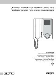
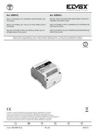
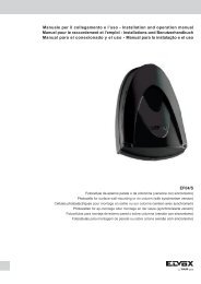
ELVOXRA- Targa per videocitofonoVideo-inter<strong>com</strong> panelPlaque de rue pour portier-vidéoVideo-TürsprechstellePlaca para vídeo-porteroTelecâmara botoneiraB- Pulsante supplementare serraturaAdditional push-button for lockPoussoir supplémentaire gâchezusätzliche TüröffnertastePulsador suplementario cerraduraBotão suplementar de trincoC- Serratura elettrica-Electric lockGâche électrique-Elektrischer TüröffnerCerradura eléctrica-Trinco eléctrico 12V~D- Telecamera con posto esternoCamera with speech unitCaméra avec micro et haut-parleurKamera mit AußenstelleCámara con aparato externoTelecâmara <strong>com</strong> posto externoE- Commutatore - Switching moduleCommutateur - UmschaltrelaisConmutador - Comutador Art. <strong>935</strong>AF- Alimentatore-Power supplyAlimentation-NetzgerätAlimentador Art. 6680L1- Modulo LED targaLed module for entrance panelModule LED pour plaque de rueLED-Modul für Klingeltableau.Módulo Led para placa.Módulo LED para botoneira.(10 moduli-modules-Modulen-módulosLED max.)30 moduli-modules-Modulen-módulosLED con/with/avec/mit/con/<strong>com</strong> Art. M83240 moduli-modules-Modulen-módulosLED con/with/avec/mit/con/<strong>com</strong> Art. 832/030APREDISPOSIZIONE CITOFONOINTERPHONE PRE-SETTINGPRÉCÂBLAGE POSTE D’APPARTEMENTVORBEREITUNG HAUSTELEFONPREDISPOSICIÓN INTERFONOPREDISPOSIÇÃO TELEFONEDSerie 8000 558-559-(570+930)(571+930)-559C(570+930A)-(571+930A)Serie 3300 558-559-559CSerie PATAVIUM 558-559-559CArt. 2550/301-302 (570+930)-(571+930)(570C+930)-(570+930A)(571+930A)-(570C+930A)Serie 8100Serie 1200Serie 1300Casellario559A - 559B559A - 559B559A - 559B559 - 559C4A- Comune autoaccensioneAuto-activation <strong>com</strong>monCommun auto-allumageGemeinsamer Ansch-lußSelbseinschaltungComún autoencendidoComun autoacendimento4C- Comune chiamate inter<strong>com</strong>unicanti.Inter<strong>com</strong>municating calls <strong>com</strong>mon.Commun appels inter<strong>com</strong>municantsGemeinsamer Anschluß InternrufeComún llamadas inter<strong>com</strong>unicantesComun chamada inter<strong>com</strong>unicanteCHART. 6200S 6 5 3 2 1 C3 AU VAC7AU12356E66P6S48494104114124134144151236E66P6S101112131415<strong>935</strong>ASCHEMA DI COLLEGAMENTO VIDEOCITOFONO MONOFAMILIARE CON MONI-TOR E CITOFONI INTERCOMUNICANTI.WIRING DIAGRAM FOR SINGLE-RESIDENCE VIDEO-INTERCOM SYSTEM WITHINTERCOMMUNICATING MONITOR AND PHONES.SCHEMA DES CONNEXIONS PORTIER-VIDÉO POUR UNE SEULE FAMILLE AVECMONITEURS ET POSTES INTERCOMMUNICANTS.ANSCHLUSSPLAN FÜR EINE BILDSPRECHANLAGE IN EINFAMILIENHÄUSERNSOWIE MONITOREN BZW. HAUSTELEFONEN MIT INTERCOM-FUNKTION.ESQUEMA DE CONEXIONADO DE VÍDEO PORTERO MONOFAMILIAR CON MONI-TORES Y TELÉFONOS INTERCOMUNICANTES.ESQUEMA DE LIGAÇÃO DE VIDEO-PORTEIRO MONIFAMILIAR COM SISTEMA DECHAMADA “SOUND SYSTEM” COM MONITORES E TELEFONES INTERCOMUNI-CANTES.75 Ohm74A4C94V1MV2MV3+ -+A+DCHCN2CN1CN1MONITORMONITEURArt. 6000 + 6200 + 6145Art. 6003 + 6200 + 614577 7 7 7 7 7 7AUAU AU AU AU AU AU AU11 1 1 1 1 1 122 2 2 2 2 2 233 3 3 3 3 3 355 5 5 5 5 5 54A 4A 4A 4A 4A 4A 4A 4A6E6E 6E 6E 6E 6E 6E 6E6P 6P 6P 6P 6P 6P 6P 6P6S6S 6S 6S 6S 6S 6S 6S4C4C 4C 4C 4C 4C 4C 4C69 10 11 12 13 14 1596 9 9 9 9 9 91010 6 10 10 10 10 101111 11 6 11 11 11 111212 12 12 6 12 12 121313 13 13 13 6 13 1314 14 14 14 14 14 6 141515 15 15 15 15 15 612 3 4 5 6 7 8ERETE-MAINSRÉSEAU-NETZRED-REDECH AU C1 C3 3- 2 1 8 7 0 15ACL1PRIM1 V1 V2 M2D34678CT+TVMCITOFONO - PHONEPOSTE - HAUSTELEFONTELÉFONO - TELEFONEArt. 6200 + N. 6152ABAU C2 1 2 3 - + S 6 7 8 - +T AM 15 0 S1 C1BN.B.In caso di ronzio sulla fonica spostareil <strong>com</strong>mutatore “A-B” situatosotto il coperchio in posizione“A”.If a humming sound is detected onthe phonic line, set slide switch“A-B” under the cover to position“A”.en cas de bourdonnement sur laligne phonique déplacer le <strong>com</strong>mutateur“A-B”, situé sous le couvercle,sur la position “A”.Ist bei der Audioverbindung einBrummton zu hören, muß derSchiebeschalter “A-B” unter demGehäusedeckel in Position “A”gebracht werden.En caso de zumbido en la fónicadesplazar el conmutador “A-B”que se encuentra debajo de latapa en la posición “A”.No caso de ruído na linha audiomudar o <strong>com</strong>utador “A-B” situadona tampa para a posição “A”.FN° vc4369CH AU C1 C3 3-2 1 7 815 07AU12356E6P6S4C6891011121314151<strong>935</strong>ASCHEMA DI COLLEGAMENTO CITOFONI INTERCOMUNICANTI SERIE PETRARCA CON POSTO ESTERNOWIRING DIAGRAM OF INTERCOMMUNICATING PHONES SERIES PETRARCA WITH SPEECH UNITSCHÉMA DES CONNEXIONS POSTES D'INTERCOMMUNICATION SÉRIE PETRARCA AVEC POSTE EXTERNE ET PO-STESSCHALTPLAN INTERNSPRECHSTELLEN SERIE PETRARCA MIT AUSSENSTELLE UND HAUSTELEFONENESQUEMA CONEXIONADO TELÉFONOS INTERCOMUNICANTES SERIE PETRARCA CON APARATO EXTERNO TELÉFO-NOSESQUEMA DE LIGAÇÃO TELEFONES INTERCOMUNICANTES SERIE PETRARCA COM POSTO ESTERNO E TELEFONESCommutatoreSwitching moduleCommutateurUmschaltrelaisConmutadorComutadorArt. <strong>935</strong>AA- Targa con posto esternoEntrance panelPlaque de rue avec poste externeKlingeltableau mit AußenstellePlaca con aparato externoBotoneira <strong>com</strong> posto externoB- Pulsante supplementare serraturaAdditional push-button for lockPoussoir supplémentaire gâchezusätzliche TüröffnertastePulsador suplementario cerraduraBotão suplementar de trincoC- Serratura elettrica-Electric lockGâche électriqueElektrischer TüröffnerCerradura eléctricaTrinco eléctrico 12V~D- Posto esterno-Speech unitMicro et haaut-parleur-AußenstelleAparato externo-Posto externoArt. 930, 930AE- CommutatoreSwitching moduleCommutateurUmschaltrelaisConmutadorComutadorArt. <strong>935</strong>AF- TrasformatoreTransformerTransformateurTransformatorTransformadorArt. 832/030L1- Modulo LED targaLed module for entrance panelModule LED pour plaque de rueLED-Modul für Klingeltableau.Módulo Led para placa.Módulo LED para botoneira.(10 moduli-modules-Modulen-módulosLED max.)30 moduli-modules-Modulen-módulosLED con/with/avec/mit/con/<strong>com</strong> Art. M83240 moduli-modules-Modulen-módulosLED con/with/avec/mit/con/<strong>com</strong> Art. 832/030Art. <strong>935</strong>AF7AU12356E6P6S4C869101112131415213RETEMAINSRÉSEAUNETZREDREDEPRIArt. 931 (931A)1 2 3- C2 6 7 8 C1 CP7AU12356E6P6S4C89610111213141537AU12356E6P6S4C89106111213141547AU12356E6P6S4C89101161213141557AU12356E6P6S4C891011126131415ALIMENTATOREPOWER SUPPLYALIMENTATIONNETZGERÄTALIMENTADORArt. 931Art. 931A0 15 AS7AU12356E6P6S4C891011121361415B7AU12356E6P6S4C8910111213146157AU12356E6P6S4C8910111213141566 7 8 9N.B.In caso di ronzio sulla fonica spostare nell’alimentatoreil filo collegato alla serratura dal morsetto15 al morsetto AS.If a humming sound is detected on the phonicline reconnect the wire connected to the lock byterminal 15 to terminal AS inside the power supply.En cas de bourdonnement sur la ligne phoniquedéplacer dans l’alimentateur le fil connecté à la serrurede la borne 15 à la borne AS.Wenn ein Geräusch am Audio gibt es, der am Türöffnerangeschlossene Draht des Netzgeräts vonKlemme 15 auf Klemme AS umstellen.En caso de zumbido en la fónica desplazar en elalimentador el hilo conectado a la cerraduradesde el borne 15 al borne AS.No caso de ruído no toque mudar, no alimentador,o condutor ligado ao trinco, do borne 15para o borne AS.L1345678DCACITOFONOPHONEPOSTEHAUSTELEFONTELÉFONOTELEFONEArt. 6200 + n° 6152N° SI611
<strong>935</strong>A<strong>935</strong>A3) Schéma CI3244. INSTALLATION MULTI-FAMILLES AVEC POR-TIERS A INTERCOMMUNICATION SUR APPARTAMENT INDIVI-DUEL.Le schéma représente la connexion de plusieurs réseaux à inter<strong>com</strong>municationprésents dans la même installation: chaque utilisateurpourra donc <strong>com</strong>muniquer librement entre les appareils de sonpropre appartement en maintenant un secret absolu de conversationaussi bien vers le poste externe que simultanément avec lesutilisateurs des autres appartements. Plusieurs conversations simultanéesà inter<strong>com</strong>munication peuvent coexister dans les appartements,ou encore, pendant que d’autres conversations à<strong>com</strong>munication interne sont en cours, d’autres utilisateurs du mêmeimmeuble peuvent <strong>com</strong>muniquer sans interférence avec le posteexterne.INSTRUCTIONS POUR LA CONNEXIONLe schéma de l’appartement n. 1 représente la connexion du nombremaximum de postes d’appartement. Pour en connecter un nombre inférieursuivre les instructions suivantes:avec trois postes d’appartement utiliser des appareils à 3 boutons-poussoirs;le premier bouton-poussoir, correspondant à la borne 7, actionnela gâche, est utilisé pour <strong>com</strong>muniquer avec le poste externe; les autresdeux boutons-poussoirs (9-10) servent aux appels d’inter<strong>com</strong>munication.On doit connecter ensuite les trois premières boîtes de raccordementde la borne 1 à la 10.INSTRUCTIONS POUR LE FONCTIONNEMENTSuivre les instructions précedemment indiquées pour le schémaVC3242.BORNES DU MONITEUR ART. 6000, 6003V1: Raccordement câble vidéo 75 Ohms; entrée (pour installationsavec câble coaxial) ou raccordement vidéo 1, entrée (pour installationssans câble coaxial)V2: Raccordement câble vidéo 75 Ohms; sortie, ou bien résistanceterminale de charge 75 Ohms (seulement pour installations aveccâble coaxial)V3: Raccordement vidéo 2 entrée pour installations sans câble coaxialM: Masse relative aux bornes V1, V2, V3+A: Non utilisé+: Positif d’alimentation, tension minimum en entrée 15 Vcc-: Négatif d’alimentation, tension minimum en entrée 15 Vcc+D: Sortie 12 Vcc pour distributeur vidéoCH: Appel pour allumage du moniteurCN2: Connecteur pour l’interface moniteurBORNES DU POSTE ART. 6200CN1: Connecteur pour interface moniteur7: Poussoir d’ouverture gâcheAU: Commande d’autoallumage du moniteur1: Écouteur2: Microphone3: Commun phonie6: Appel inter<strong>com</strong>municant6E: Appel plaque de rue6P: Appel porte palière6S: Sortie pour alimentation sonnerie (+18Vcc, seulement pour desinstallations vidéo)8÷15:Poussoir des services auxiliaires ou pour appel inter<strong>com</strong>municant3) Esquema CI3244. INSTALAÇÃO PLURIFAMILIAR COM TELE-FONES INTERCOMUNICANTES EM APARTAMENTOS.O esquema representa a ligação de várias redes inter<strong>com</strong>unicantesexistentes na mesma instalação: cada utente poderá também<strong>com</strong>unicar entre os aparelhos do próprio apartamento mantendoum segredo na conversação tanto <strong>com</strong> o posto externo <strong>com</strong>o simultaneamente<strong>com</strong> os utentes das outras habitações. Podem coexistirvárias conversações inter<strong>com</strong>unicantes simultâneas nosapartamentos ou enquanto estão a efectuar-se conversações inter<strong>com</strong>unicantesinternas, outros utentes do mesmo edificio podem<strong>com</strong>unicar sem interferência <strong>com</strong> o posto externo.INSTRUÇÕES PARA A LIGAÇÃOO esquema do apartamento n. 1 representa a ligação do número máximode telefones. Para se ligar um número inferior proceder <strong>com</strong>o o indicadoa seguir: <strong>com</strong> tres telefones utilizam-se aparelhos <strong>com</strong> 3 botões;o primeiro botão (correspondiente ao terminal 7) para o trinco; os outrosdois botões (correspondentes os terminais 9-10) para chamadas inter<strong>com</strong>unicantes.Ligar-se ão ainda très bornes do terminal 1 ao 10.PRINCÍPIO DE FUNCIONAMENTOSeguir as instruções descritas precedentemente pelo esquemaVC3242.TERMINAIS DO MONITOR ART. 6000, 6003V1: Ligação do cabo de vídeo de 75 Ohm, entrada (para instalações<strong>com</strong> cabo coaxial) ou ligação de vídeo 1, entrada (para instalaçõessem cabo coaxial).V2: Ligação do cabo de vídeo de 75 Ohm, ou resistência de fecho 75Ohm (só para instalações <strong>com</strong> cabo coaxial)V3: Ligação de vídeo 2 entradas para instalaçãoes sem cabo coaxial.M: Massa referente aos bornes V1, V2, V3.+A: Não utilizado+: Positivo da alimentação, tensão mínima na entrada 15V c.c.-: Negativo da alimentação, tensão mínima na entrada 15V c.c.D: Saída de 12V c.c. para o distribuidor de vídeo.CH: Chamada acendimento do monitorCN2: Conector para ligação ao monitorTERMINAIS DO TELEFONE ART. 6200CN1: Conector para ligação ao monitor7: Botão para abertura do trincoAU: Comando de autoacendimento do monitor1: Receptor corneta2: Microfone3: Linha audio <strong>com</strong>um6: Chamada inter<strong>com</strong>unicante6E: Chamada da botoneira6P: Chamada do patamar6S: Saída para alimentação das campainhas (+18Vcc, só para instalaçöesvídeo)8÷15: Botão para serviços auxiliares ou para chamadasinter<strong>com</strong>unicantes2) Schema vc4374. IMPIANTO PLURIFAMILIARE CON MONITORE/O CITOFONI INTERCOMUNICANTI SU SINGOLO APPARTA-MENTOLo schema rappresenta il collegamento di più reti inter<strong>com</strong>unicantipresenti nello stesso impianto: ogni utente potrà quindi inter<strong>com</strong>unicareliberamente tra gli apparecchi del proprio appartamento mantenendoun assoluto segreto di conversazione sia verso il postoesterno che contemporaneamente con gli utenti delle altre abitazioni.Possono coesistere più conversazioni contemporanee inter<strong>com</strong>unicantinegli appartamenti oppure, mentre sono in attoconversazioni inter<strong>com</strong>unicanti, altri utenti dello stesso stabile possono<strong>com</strong>unicare senza interferenza con il posto esterno. Per il collegamentoe il funzionamento dell’impianto seguire le istruzioniprecedentemente descritte per lo schema vc3242.2) Diagram vc4374. MULTI-RESIDENCE COMMUNICATION SY-STEM WITH MONITOR AND/OR INTERCOM PHONES IN SIN-GLE APARTMENT.The diagram shows the interconnection of several inter<strong>com</strong> networksin the same system. Each user can therefore freely <strong>com</strong>municatefrom one inter<strong>com</strong> unit to another in his/her own apartment,maintaining <strong>com</strong>plete conversation privacy with the entrance paneland, at the same time, with users in other residences. More thanone inter<strong>com</strong> conversation can take place at the same time in apartments.During conversation between one internal inter<strong>com</strong> unit andanother, other users in the same building can also <strong>com</strong>municatewith the external entrance panel, without interference. Follow theinstructions previously given for diagram vc2988 to connect andoperate the system.2) Schéma vc4374. INSTALLATION MULTI-FAMILLES AVEC MO-NITEUR ET/OU POSTES INTERCOMMUNICANTS SUR APPAR-TAMENT INDIVIDUEL.Le schéma représente la connexion de plusieurs réseaux à inter<strong>com</strong>municantsprésents dans la même installation: chaque utilisateurpourra donc <strong>com</strong>muniquer librement entre les appareils de sonpropre appartement en maintenant un secret absolu de conversationaussi bien vers le poste externe que simultanément avec lesutilisateurs des autres appartements. Plusieurs conversations simultanéesà inter<strong>com</strong>munication peuvent coexister dans les appartements,ou encore, pendant que d’autres conversations à<strong>com</strong>munication internes sont en cours, d’autres utilisateurs dumême immeuble peuvent <strong>com</strong>muniquer sans interférence avec leposte externe. Pour la connexion et le fonctionnement de l’installationrespecter les instructions préalablement décrites pour leschéma vc3242.2) Anlagenplan vc4374. MEHRFAMILIENHAUSANLAGE MIT MO-NITOREN ODER HAUSTELEFONEN MIT INTERCOM-FUN-KTION IN DER EINZELNEN WOHNUNG.Der Anlagenplan zeigt die Verbindung von mehreren Inter<strong>com</strong>-Netzenin derselben Anlage. Jeder Teilnehmer kann frei Inter<strong>com</strong>-Gesprächemit den Innenstellen seiner Wohnung führen, wobeigegenüber der Außenstation und den Teilnehmern der anderenWohnungen ein vollständiger Mithörschutz gewährleistet ist. Essind mehrere gleichzeitige Gespräche zwischen Inter<strong>com</strong>-Haustelefonenin den Wohnungen oder Gespräche von Teilnehmern mitder Außenstation während interner Inter<strong>com</strong>-Gespräche möglich.Für den Anschluß und den Betrieb der Anlage siehe die Anweisungenweiter oben für den Anlagenplan vc3242.2) Esquema vc4374. INSTALACIÓN MULTIFAMILIAR CON MONI-TOR E/O TELÉFONOS INTERCOMUNCANTES EN CADA VI-VIENDA.El esquema representa el conexionado de varias redes inter<strong>com</strong>unicantespresentes en la misma instalación: cada usuario podrá porlo tanto <strong>com</strong>unicar liberamente con los otros aparatos del propioapartamiento manteniendo un absoluto secreto de conversaciónsea hacia el aparato externo sea con los otros usuarios de las otrasviviendas. Se pueden efectuar varias conversaciones simultáneasy inter<strong>com</strong>unicantes entre los usuarios de una misma vivienda otambién, mientras se efectúan conversaciones inter<strong>com</strong>unicantesen una vivienda, otros usuarios del mismo edificio (pero de otrasviviendas) pueden <strong>com</strong>unicar sin interferencias con el aparato externo.Para el conexionado y el funcionamiento de la instalaciónseguir las instrucciones precedentemente descritas en el esquemavc3242.2) Esquema vc4374. INSTALAÇÃO PLURIFAMILIAR COM MONI-TORES E/OU TELEFONES INTERCOMUNICANTES EM APAR-TAMENTOS.O esquema representa a ligação de várias redes inter<strong>com</strong>unicantesexistentes na mesma instalação: cada utente poderá também<strong>com</strong>unicar entre os aparelhos do próprio apartamento mantendoum segredo na conversação tanto <strong>com</strong> o posto externo <strong>com</strong>o simultaneamente<strong>com</strong> os utentes das outras habitações. Podem coexistirvárias conversações inter<strong>com</strong>unicantes simultâneas nosapartamentos ou enquanto estão a efectuar-se conversações inter<strong>com</strong>unicantesinternas, outros utentes do mesmo edificio podem<strong>com</strong>unicar sem interferência <strong>com</strong> o posto externo. Para a ligaçãoe funcionamento da instalação, seguir as instruções anteriormentedescritas para o esquema vc3242.125
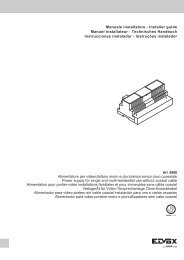
<strong>935</strong>A<strong>935</strong>AESEMPI DI COLLEGAMENTO CON DIVERSO NUMERO DI MONITOR E CITOFONI INTERCOMUNICANTI PER UN MASSIMO DI8 APPARECCHI.WIRING EXAMPLE WITH DIFFERENT NUMBER OF INTERCOMMUNICATING MONITORS AND PHONES UP TO 8 UNITS MAX.EXEMPLES DE CONNEXIONS AVEC UN NOMBRE VARIABLE DE MONITEURS ET POSTES INTERCOMMUNICANTS POUR UNMAXIMUM DE 8 APPAREILS.SCHALTPLAN MIT VERSCHIEDENER ANZAHL VON MONITOREN UND HAUSTELEFONEN MIT INTERNER SPRECHMÖGLI-CHKEIT FÜR MAX. 8 GERÄTE.EJEMPLOS DE CONEXIONADO CON UN NÚMERO DIFERENTE DE MONITORES Y TELÉFONOS INTERCOMUNICANTES PORUN MÁXIMO 8 APARATOS.EXEMPLOS DE LIGAÇÃO COM VÁRIOS MONITORES E TELEFONES INTERCOMUNICANTES PARA UM MÁXIMO DE 8 APA-RELHOS.+-S123CHAUC3VV+-S123CHAUC3FIG. 3V1MV2MV3+A+-+DCHCN2CN1V1MV2MV3+A+-+DCHCN2CN1AlimentatorePower supplyAlimentationNetzgerätAlimentadorArt. 658375ohm77AUAU112233556E6E6P6P6S6S4A4A884C4C69961010111112121313141415 151277AUAU112233556E6E6P6P6S6S4A4A884C4C69961010111112121313141415 1512PRIV1MV2MV3+A+-+DCHCN2CN115 0FIG. 12 monitor e 6 citofoni inter<strong>com</strong>unicanti2 monitors and 6 Inter<strong>com</strong>municating phones2 moniteurs et 6 postes inter<strong>com</strong>municants2 Monitore und 6 internsprechstellen2 monitoresy 6 teléfonos inter<strong>com</strong>unicantesV1 2 monitores et 6 telefones inter<strong>com</strong>unicantesMV2MONITORMMONITEURV3Art. 6000 + 6200 + 6145+AArt. 6003 + 6200 + 6145++D -CHCITOFONO - PHONEPOSTE - HAUSTELEFONTELÉFONO - TELEFONEArt. 6200 + n° 6152CN2CN1CN17 7 7 7 7 7S77AU AU AU AU AU AUAUAU1 1 1 1 1 11112 2 2 2 2 22223 3 3 3 3 33335 5 5 5 5 5556E 6E 6E 6E 6E 6ECH6E6E6P 6P 6P 6P 6P 6P6P6P6S 6S 6S 6S 6S 6S6S6S4A 4A 4A 4A 4A 4AAU4A4A8 8 8 8 8 8884C 4C 4C 4C 4C 4CC34C4C9 9 9 9 9 96910 10 10 10 10 10966 11 11 11 11 11101011 6 12 12 12 12111112 12 6 13 13 13121213 13 13 6 14 14131314 14 14 14 6 15141415 15 15 15 15 615153 4 5 6 7 8124 monitor e 4 citofoni inter<strong>com</strong>unicanti4 monitors and 4 Inter<strong>com</strong>municating phones4 moniteurs et 4 postes inter<strong>com</strong>municants4 Monitore und 4 internsprechstellen4 monitoresy 4 teléfonos inter<strong>com</strong>unicantes4 monitores et 4 telefones inter<strong>com</strong>unicantes+I C +U -A B CV1MV2MV3+A+-+DCHCN2CN177 7 7 7AUAU AU AU AU11 1 1 122 2 2 233 3 3 355 5 5 56E6E 6E 6E 6E6P6P 6P 6P 6P6S6S 6S 6S 6S4A4A 4A 4A 4A88 8 8 84C4C 4C 4C 4C99 9 9 91010 10 10 10611 11 11 11116 12 12 121212 6 13 131313 13 6 141414 14 14 615 15 15 15 153 4 5 6 7- +U +IPRI75ohmV1MV2MV3+A++D -CHCN2CN1CN1RelèRelayRelaisArt. 934MONITORMONITEURArt. 6000 + 6200 + 6145Art. 6003 + 6200 + 61457AU12356E6P6S4A84C910111213141568CITOFONO - PHONEPOSTE - HAUSTELEFONTELÉFONO - TELEFONEArt. 6200 + n° 6152V+-V+-S123CHAUC3FIG. 4V1MV2MV3+A+-+DCHCN2CN1V1MV2MV3+A++D -CHCN2CN17AU12356E6P6S4A84C691011121314151V1MV2MV3+A+-+DCHCN2CN1Alimentatore-Power supplyAlimentation-NetzgerätAlimentador Art. 6582AlimentatorePower supplyAlimentationNetzgerätAlimentadorArt. 6583V1MV2MV3+A+-+DCHCN2CN17AU12356E6P6S4A84C961011121314152AB75ohmPRI 15 0 +I C +U -CV1MV2MV3+A+-+DCHCN2CN17AU12356E6P6S4A84C910611121314153- +U +I A B CV1MV2MV3+A++D -CHCN2CN17AU12356E6P6S4A84C109611121314153- +U +IPRIFIG. 23 monitor e 5 citofoni inter<strong>com</strong>unicanti3 monitors and 5 Inter<strong>com</strong>municating phones3 moniteurs et 5 postes inter<strong>com</strong>municants3 Monitore und 5 internsprechstellen3 monitoresy 5 teléfonos inter<strong>com</strong>unicantes3 monitores et 5 telefones inter<strong>com</strong>unicantesCN17AU12356E6P6S4A84C910116121314157 7AU AU1 12 23 35 56E 6E6P 6P6S 6S4A 4A8 84C 4C9 910 1011 1112 126 1313 614 1415 15D7AU12356E6P6S4A84C119106121314154PRI7AU12356E6P6S4A84C910111213146157AU12356E6P6S4A84C910111213141564 5 6 7 85 monitor e 3 citofoni inter<strong>com</strong>unicanti5 monitors and 3 Inter<strong>com</strong>municating phones5 moniteurs et 3 postes inter<strong>com</strong>municants5 Monitore und 3 internsprechstellen5 monitores y 3 teléfonos inter<strong>com</strong>unicantes5 monitores et 3 telefones inter<strong>com</strong>unicantesV1MV2MV3+A+-+DCHCN2CN175ohmMONITORMONITEURArt. 6000 + 6200 + 6145Art. 6003 + 6200 + 6145V1MV2MV3+A+-+DCHCN2CN1RelèRelayRelaisArt. 934CN1CITOFONO - PHONEPOSTE - HAUSTELEFONTELÉFONO - TELEFONEArt. 6200 + n° 61527 7 7AU AU AU1 1 12 2 23 3 35 5 56E 6E 6E6P 6P 6P6S 6S 6S4A 4A 4A8 8 84C 4C 4C12 13 149 9 910 10 1011 11 116 12 1213 6 1314 14 615 15 155 6 7MONITORMONITEURArt. 6000 + 6200 + 6145Art. 6003 + 6200 + 61457AU12356E6P6S4A84C159101112131468CITOFONOPHONEPOSTEHAUSTELEFONTELÉFONOTELEFONEArt. 6200+ n° 61523) Schema CI3244. IMPIANTO PLURIFAMILIARE CON CITOFONI INTER-COMUNICANTI SU SINGOLO APPARTAMENTOLo schema rappresenta il collegamento di più reti inter<strong>com</strong>unicanti presentinello stesso impianto: ogni utente potrà quindi inter<strong>com</strong>unicare liberamentetra gli apparecchi del proprio appartamento mantenendo un assoluto segretodi conversazione sia verso il posto esterno che contemporaneamente con gliutenti delle altre abitazioni. Possono coesistere più conversazioni contemporaneeinter<strong>com</strong>unicanti negli appartamenti oppure, mentre sono in atto conversazioniinter<strong>com</strong>unicanti, altri utenti dello stesso stabile possono<strong>com</strong>unicare senza interferenza con il posto esterno.ISTRUZIONI PER IL COLLEGAMENTOLo schema dell’appartamento n. 1 rappresenta il collegamento del massimo numerodi citofoni. Per collegarne un numero inferiore procedere <strong>com</strong>e nelle istruzionisottoriportate. Con tre citofoni si utilizzano apparecchi con 3 pulsanti, il primopulsante, corrispondente al morsetto n. 7, per la serratura; gli altri due, corrispondentiai morsetti 9 e 10, per le chiamate inter<strong>com</strong>unicanti. Si collegheranno quindile prime tre morsettiere dal morsetto 1 al 10.PRINCIPIO DI FUNZIONAMENTOSeguire le istruzioni precedentemente descritte per lo schema VC3242.MORSETTI MONITOR ART. 6000, 6003V1: Collegamento cavo video 75 Ohm, entrata (per impianti con coassiale) ocollegamento video 1, entrata (per impianti senza cavo coassiale).V2: Collegamento cavo video 75 Ohm; uscita, oppure resistenza terminale dicarico 75 Ohm (solo per impianti con cavo coassiale)V3: Collegamento video 2 entrata per impianti senza cavo coassiale.M: Massa relativa ai morsetti V1, V2, V3.+A: Non usato.+: Positivo alimentazione, tensione minima in arrivo 15V c.c.-: Negativo alimentazione, tensione minima in arrivo 15V c.c.+D: Uscita 12V c.c. per distributore videoCH: Chiamata per accensione monitorCN2: Connettore per interfaccia monitorMORSETTI CITOFONO ART. 6200CN1: Connettore per interfaccia monitor7: Pulsante per apertura serraturaAU: Comando autoaccensione monitor1: Ricevitore cornetta2: Microfono cornetta3: Comune fonica6: Chiamata inter<strong>com</strong>unicante6E: Chiamata da targa6P: Chiamata fuoriporta6S: Uscita per alimentazione suonerie (+18Vcc, solo per impianti video)8÷15: Pulsante per servizi ausiliari o per chiamate inter<strong>com</strong>unicanti3) Diagram CI3244. MULTI-RESIDENCE COMMUNICATION SYSTEM WITHINTERCOM PHONES IN SINGLE APARTMENT.The diagram shows the interconnection of several inter<strong>com</strong> networks in thesame system. Each user can therefore freely <strong>com</strong>municate from one inter<strong>com</strong>unit to another in his/her own apartment, maintaining <strong>com</strong>plete conversationprivacy with the entrance panel and, at the same time, with users in other residences.More than one inter<strong>com</strong> conversation can take place at the sametime in apartments. During conversation between one internal inter<strong>com</strong> unitand another, other users in the same building can also <strong>com</strong>municate with theexternal entrance panel, without interference.WIRING INSTRUCTIONSThe N. 1 apartment wiring diagram shows the maximum number of interphonesconnections. To connect fewer interphones, proceed as it follows: with three interphonesuse items with 3 push-buttons: push-button 1 (corresponding to terminal 7)operates door lock; the other two push-buttons (9-10) are used for inter<strong>com</strong>municatingcalls. Connect then the first three terminal blocks (terminal 1 to 10).OPERATING INSTRUCTIONSFollow instructions previously indicated on diagram VC3242.MONITOR TERMINALS ART. 6000, 6003V1: 75 Ohm video input connection for systems with co-ax cable or video 1 inputconnection for systems without co-ax cableV2: 75 Ohm video output connection or 75 Ohm closing resistor (for systemswith co-ax cable only)V3: Video 2 input connection for systems without co-ax cableM: Earth for terminals V1, V2 and V3.+A: Not used+: Power supply (positive), minimum voltage 15 Vdc-: Power supply (negative), minimum voltage 15 Vdc+D. 12 Vdc output for video distributorCH: Monitor activation callCN2: Monitor interface connectorINTERPHONE TERMINALS ART. 6200CN1: Monitor interface connector7: Door lock release buttonAU: Monitor auto-activation control1: Handset receiver2: Handset microphone3: Phonic <strong>com</strong>mon6: Inter<strong>com</strong> callSE: Entrance panel call6P: Landing call6S: Chime power output (+18Vcc, only for video installation)8÷15: Auxiliary services button or for inte<strong>com</strong>municating calls3) Anlagenplan CI3244. MEHRFAMILIENHAUSANLAGE MIT HAUSTELE-FONEN MIT INTERCOM-FUNKTION IN DER EINZELNEN WOHNUNG.Der Anlagenplan zeigt die Verbindung von mehreren Inter<strong>com</strong>-Netzen in derselbenAnlage. Jeder Teilnehmer kann frei Inter<strong>com</strong>-Gespräche mit den Innenstellenseiner Wohnung führen, wobei gegenüber der Außenstation undden Teilnehmern der anderen Wohnungen ein vollständiger Mithörschutz gewährleistetist. Es sind mehrere gleichzeitige Gespräche zwischen Inter<strong>com</strong>-Haustelefonen in den Wohnungen oder Gespräche von Teilnehmern mit derAußenstation während interner Inter<strong>com</strong>-Gespräche möglich.ANWEISUNGEN FÜR DEN ANSCHLUSSDer Schaltplan der ersten Wohnung stellt die Verbindung der höchstmöglichenAnzahl von Haustelefonen dar. Beim Anschluß von weniger Haustelefonen müssenfolgende Anweisungen befolgt werden: bei drei Haustelefonen verwendet manHörer mit 3 Tasten; Taste 1 (entsprechende Klemme 7) betätigt den elektrischenTüröffner; die restlichen Tasten (entsprechende Klemmen 9-10) sind für die Interngespräche.Anschließen Sie dann die ersten drei Klemmenbretter von Klemme1 bis Klemme 10.FUNKTIONWEISEFolgen Sie die vorherbeschriebenen Anweisungen für die Shaltplan VC3242.MONITOR KLEMMEN ART. 6000, 6003V1: Anschluß für Monitorkabel 75 Ohm, Eingang (bei Anlagen mit Koaxialkabel)oder Anschluß Monitor 1, Eingang (für Anlagen ohne Koaxialkabel).V2: Anschluß für Monitorkabel 75 Ohm; Ausgang bzw. Abschlußwiderstand 75Ohm (nur für Anlagen mit Koaxialkabel).V3: Anschluß Monitor 2 Eingang bei Anlagen ohne KoaxialkabelM: Masse für Klemmen V1, V2, V3+A: Nicht verwendet+: Pluspol des Netzteils, Mindest-Eingangsspannung 15 V DC-: Minuspol des Netzteils, Mindest-Eingangsspannung 15 V DC+D: Ausgang 12 V DC für Video-VerteilermodulCH: Rufsignal für MonitoreinschaltungCN2: Steckverbinder für Monitor-SchnittstelleHAUSTELEFON KLEMMEN ART. 6200CN1: Steckverbinder für Monitor-Schnittstelle7: Schalter für TüröffnerAU:1: Lautsprecher des Hörers2: Mikrophon des Hörers3: Gemeinsam d. Sprechteils6: Ruf d. HaussprechanlageBefehl für Selbsteinschaltung d. MonitorsSE: Ruf von KlingeltableauSP: Ruf von Türklingel6S: Ausgang für Läutwerk-Stromversorgung (+18Vcc, nur für Videoanlagen)8÷15: Schalter für Zusatzfunktionen oder Tasten für Internrufe3) Esquema CI3244. INSTALACIÓN MULTIFAMILIAR CON TÉLEFONOS IN-TERCOMUNCANTES EN CADA VIVIENDA.El esquema representa el conexionado de varias redes inter<strong>com</strong>unicantespresentes en la misma instalación: cada usuario podrá por lo tanto <strong>com</strong>unicarliberamente con los otros aparatos del propio apartamiento manteniendoun absoluto secreto de conversación sea hacia el aparato externo sea con losotros usuarios de las otras viviendas. Se pueden efectuar varias conversacionessimultáneas y inter<strong>com</strong>unicantes entre los usuarios de una misma viviendao también, mientras se efectúan conversaciones inter<strong>com</strong>unicantesen una vivienda, otros usuarios del mismo edificio (pero de otras viviendas)pueden <strong>com</strong>unicar sin interferencias con el aparato externo.INSTRUCCIONES PARA EL CONEXIONADOEl esquema del apartamiento n. 1 representa el conexionado del máximo númerode teléfonos. Para conectar un número inferior proceder <strong>com</strong>o sigue: con tres teléfonosse utilizan aparatos con 3 pulsadores; el primer pulsador (correspondienteal borne 7) abre la cerradura; los otros dos pulsadores (correspondientes a losbornes 9-10) sirven para las llamadas inter<strong>com</strong>unicantes. Conectar luego las primerastres cajas de conexiones del borne 1 al 10.PRINCIPIO DE FUNCIONAMIENTOSeguir las intrucciones descritas precedentemente para el esquema VC3242.BORNES MONITOR ART. 6000, 6003V1: Conexionado cable vídeo 75 Ohm, entrada (para instalaciones con cablecoaxial) o conexionado vídeo 1, entrada (para instalaciones sin cable coaxial).V2: Conexionado cable vídeo 75 Ohm; salida, o resistencia terminal con carga75 Ohm (solamente para instalaciones con cable coaxial).V3: Conexionado vídeo 2 entrada para instalaciones sin cable coaxial.M: Masa relativa a los bornes V1, V2, V3.+A. No utilizado+: Positivo alimentación, tensión mínima en llegada 15V c.c.-: Negativo alimentación, tensión mínima en llegada 15V c.c.+D: Salida 12V c.c. para distribuidor vídeoC: Llamada para encendido monitorCN2: Conector para interface monitorBORNES INTERFONO ART. 6200CN1: Conector para interface monitor7: Pulsador para abertura cerraduraAU: Mando autoencendido monitor1: Receptor microteléfono2: Micrófono microteléfono3: Común fónica6: Llamada inter<strong>com</strong>unicante6E: Llamada desde la placa6P: Llamada puerta apartamiento6S: Salida para alimentación timbre (+18Vcc, sólo para instalaciones vídeo)8÷15: Pulsador para servicios auxiliares o para llamadas inter<strong>com</strong>unicantes611
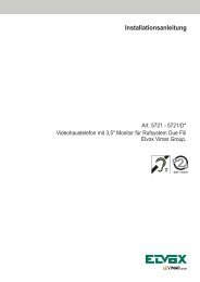
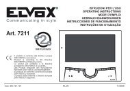
R<strong>935</strong>A<strong>935</strong>ASCHEMA DI COLLEGAMENTO CITOFONI INTERCOMUNICANTI SU SINGOLO APPARTAMENTO.WIRING DIAGRAM OF INTERCOM PHONES IN SINGLE APARTMENT.SCHEMA DES CONNEXIONS INTERCOMMUNICANTS POUR CHAQUE APPARTEMENT.ANSCHLUSSPLAN FÜR HAUSTELEFONEN MIT INTERCOM-FUNKTION IN DER EINZELNEN WOHNUNG.ESQUEMA DE CONEXIONADO TELÉFONOS INTERCOMUNICANTES EN UNA VIVIENDA SIMPLE.ESQUEMA DE LIGAÇÃO TELEFONES INTERCOMUNICANTES EM APARTAMENTOS.CITOFONO - PHONEPOSTE - HAUSTELEFONTELÉFONO - TELEFONEArt. 6200CA7AU12356E66P6S4849410411412413414415CA7AU12356E66P6SCITOFONO - PHONEPOSTE - HAUSTELEFONTELÉFONO - TELEFONEArt. 875/100 - 875/001Art. 8872 - 8875CITOFONO - PHONEPOSTE - HAUSTELEFONTELÉFONO - TELEFONEArt. 6200N° ci3244B1234/567871236E66P6S4C89101112131415FF1 2 3 C2 C1 S CHFFALIMENTATOREPOWER SUPPLYALIMENTATIONNETZGERÄTALIMENTADORArt. 931L1- Lampada luce targaBulb for panel lightingLampe d’éclairage plaqueBirne für TastenbeleuchtungLámpara luz escaleraLâmpada da luz da botoneira(3x24V 3W max.)10x24V 3W con/with Art. M83216X24V 3W con/with Art. 832/030ECH AU C1 C3 3- 2 1 7 8 15 0ERETEMAINSRÉSEAUNETZREDREDE7AU12356E6P6S4C6891011121314151RETEMAINSRÉSEAUNETZREDREDE0PRI15PRI7 7 7 7 7 7AU AU AU AU AU AU1 1 1 1 1 12 2 2 2 2 23 3 3 3 3 35 5 5 5 5 56E 6E 6E 6E 6E 6E6P 6P 6P 6P 6P 6P6S 6S 6S 6S 6S 6S4C 4C 4C 4C 4C 4C8 9 10 11 12 136 8 8 8 8 89 6 9 9 9 910 10 6 10 10 1011 11 11 6 11 1112 12 12 12 6 1213 13 13 13 13 614 14 14 14 14 1415 15 15 15 15 152 3 4 5 6 7PRI1 2 3- C2 6 7 8 C1 0 15 ASCH AU C1 C3 3- 2 1 7 8 15 0 0 15CITOFONO - PHONEPOSTE - HAUSTELEFONTELÉFONO - TELEFONEArt. 6200 + n° 61527 7 7 7AU AU AU AU1 1 1 12 2 2 23 3 3 35 5 5 56E 6E 6E 6E6P 6P 6P 6P6S 6S 6S 6S4C 4C 4C 4C6 8 9 108 6 8 89 9 6 910 10 10 6FF1 2 3 4RETE-MAINSRÉSEAU-NETZRED-REDE7AU12356E6P6S4C14891011121361587AU12356E6P6S4C1589101112131469BCITOFONO - PHONEPOSTE - HAUSTELEFONTELÉFONO - TELEFONEArt. 6200 + n° 6152COLORE CONDUTTORI - CONDUCTOR COLOURCOULEUR DES CONDUCTEURS - FARBE DER LEITUNGENCOLOR CONDUCTORES - CÔR DOS CONDUTORESN.B.In caso di ronzio sulla fonica spostare nell’alimentatore ilfilo collegato alla serratura dal morsetto 15 al morsetto AS.If a humming sound is detected on the phonic line reconnectthe wire connected to the lock by terminal 15 to terminalAS inside the power supply.En cas de bourdonnement sur la ligne phonique déplacer dansl’alimentateur le fil connecté à la serrure de la borne 15 à laborne AS.Wenn ein Geräusch am Audio gibt es, der am Türöffner angeschlosseneDraht des Netzgeräts von Klemme 15 auf KlemmeAS umstellen.En caso de zumbido en la fónica desplazar en el alimentadorel hilo conectado a la cerradura desde el borne 15 alborne AS.No caso de ruído no toque mudar, no alimentador, o condutorligado ao trinco, do borne 15 para o borne AS.L1345678DCCOLORE CONDUTTORI - CONDUCTOR COLOURCOULEUR DES CONDUCTEURS - FARBE DER LEITUNGENCOLOR CONDUCTORES - CÔR DOS CONDUTORESAA- Targa con posto esternoEntrance panelPlaque de rue avec poste externeKlingeltableau mit AußenstellePlaca con aparato externoBotoneira <strong>com</strong> posto externoB- Pulsante supplementare serraturaAdditional push-button for lockPoussoir supplémentaire gâchezusätzliche TüröffnertastePulsador suplementario cerraduraBotão suplementar de trincoC- Serratura elettrica-Electric lockGâche électriqueElektrischer TüröffnerCerradura eléctricaTrinco eléctrico 12V~D- Posto esterno-Speech unitMicro et haaut-parleur-AußenstelleAparato externo-Posto externoArt. 930, 930AE- Commutatore-Switching moduleCommutateur-UmschaltrelaisConmutador-Comutador Art. <strong>935</strong>AF- Trasformatore-TransformerTransformateur-TransformatorTransformador Art. 832/030N.B.Gli schemi riprodotti (pag. 6) rappresentano impianti monofamiliari inter<strong>com</strong>unicantio impianti plurifamiliari inter<strong>com</strong>unicanti. Per impianticon più appartamenti inter<strong>com</strong>unicanti (plurifamiliari), collegare il morsettoN°6E dei monitor o dei citofoni al pulsante della targa esterna relativoall’appartamento, mentre per impianti monofamiliari collegaretutti i morsetti 6E dei monitor e dei citofoni allo stesso pulsante dellatarga. Nel caso che si colleghino più di tre apparecchi con lo stesso filodi chiamata aggiungere l’Art. 934 dopo il terzo apparecchio e utilizzarloper rigenerare la chiamata di 4 apparecchi.N.B.The above mentioned (pag. 6) wiring diagrams refer to an inter<strong>com</strong>municatinginstallation for single or several residences. On installationswith more inter<strong>com</strong>municating flats (multifamilal), connect terminal N.6E on monitors or on interphones to the door entry panel terminal relatedto the same appartment, while on single residence installationsconnect all terminals 6E of monitors and interphones to the same doorentry panel push-button. If more than 3 sets are connected to the samecall wire add Art. 934 after the third set and use it to re-generate the callfor 4 sets.N.B.Les schémas (pag. 6) illustrent des raccordements relatifs à une installationinter<strong>com</strong>municante mono ou multifamiliale. Pour les installationsavec plusieurs appartements inter<strong>com</strong>municants (multifamilial),connecter la borne N. 6E des moniteurs ou des postes d’appartementau poussoir de la plaque de rue relatif à l’appartement; au contrairepour les installations monofamiliales il faut connecter toutes les bornes8 des moniteurs et des postes d’appartement au même poussoir de laplaque de rue. Si on connecte plus de trois appareils au même fil d’appelajouter l’Art. 934 après le troisième appareil et l’utiliser pour régénererl’appel de 4 appareils.N.B.Die obigen Verdrahtungspläne (pag. 6) gelten für Wechselsprechanlagenfür Ein- oder Mehrerenfamilienhäuser. Für Anlagen mit mehrerenWechselsprechwohnungen (Mehrerenfamilien) die Klemme N. 6E derMonitoren oder der Haustelefonen an die der Wohnung entsprechendeKlingeltableautaste anschließen, während für Einfamilienhausanlagenalle Klemme N. 6E der monitoren und der Haustelefonen an dieselbeKlingeltableautaste anschließen. Sollen mehr als drei Geräten an dieselbeRuftaste angeschlossen werden, wird Art. 934 nach dem drittenGerät eingefügt und für die Wiedererzeugung von 4 Geräten benutzt.N.B.En los esquemas (pag. 6) que siguen los conexionados son relativosa instalaciones inter<strong>com</strong>unicantes mono o multifamiliares. Para instalacionescon varios apartamentos inter<strong>com</strong>unicantes (multifamiliares),conectar el borne N. 6E de los monitores o de los interfonos al pulsadorde la placa externa relativo al apartamiento, mientras que para lasinstalaciones monofamiliares hay que conectar todos los bornes 6Ede los monitores y de los interfonos al mismo pulsador de la placa. Sise conectan varios aparatos al mismo hilo de llamada hay que añadirel Art. 934 después del tercer aparato, que sirve para regenerar la llamadade 4 aparatos.N.B.Nos esquemas (pag. 6) reproduzidos as ligaçöes referem-se a umainstalação mono ou multifamiliar inter<strong>com</strong>unicante. Nas instalaçöes<strong>com</strong> mais apartamentos inter<strong>com</strong>unicantes (multifamiliares), ligar oborne N. 6E dos monitores ou dos telefones ao botão da botoneira relativoao apartamento, ao contrário nas instalaçöes monofamiliaresdevem-se ligar todos os bornes N. 6E dos monitores e dos telefonesao mesmo botão da botoneira. No caso ligam-se mais de três aparelhosao mesmo fio de chamada juntar o Art. 934 depois do terceriroaparelho e o utilizar para regenerar a chamada de 4 aparelhos.107
SCHEMA DI COLLEGAMENTO VIDEOCITOFONO PLURIFAMILIARE CON MONITOR E/O CITOFONI INTERCOMUNICANTI SU SINGOLO APPARTAMENTO.WIRING DIAGRAM FOR MULTI-RESIDENCE VIDEO-INTERCOM SYSTEM WITH MONITOR AND/OR INTERCOM PHONES IN SINGLE APARTMENT.SCHEMA DE CONNEXION PORTIER-VIDEO MULTI-FAMILLES AVEC MONITEUR ET/OU POSTES INTERCOMMUNICANTS POUR CHAQUE APPARTEMENT.ANSCHLUSSPLAN FÜR EINE BILDSPRECHANLAGE IN MEHRFAMILIENHÄUSERN MIT MONITOREN BZW. HAUSTELEFONEN MIT INTERCOM-FUNKTION IN DER EINZELNEN WOH-NUNG.ESQUEMA DE CONEXIONADO PARA VÍDEO PORTERO MULTIFAMILIAR CON MONITORES Y/O TELÉFONOS INTERCOMUNICANTES EN UNA VIVIENDA SIMPLE.ESQUEMA DE LIGAÇÃO DE VIDEO-PORTEIRO PLURIFAMILIAR COM MONITORES E/OU TELEFONES INTERCOMUNICANTES EM APARTAMENTOS.ELVOX8MONTANTE MONITOR - MONITOR CABLE RISERCOLONNE MONTANTE MONITEURS-MONITORSTEIGLEITUNGMONTANTE MONITOR-COLUNA MONTANTE PARA OS MONITORESCH S 6 5 3 2 1 C2 AU +D VCH AU C1 C3 3- 2 1 7 8 15 0EPRI* #0 15V65+DS123AUCHC2C375 OhmV1MV2MV3+A+-+DCH77 7AUAU AU11 122 233 355 54A4A 4A6E6E 6E6P6P 6P6S6S 6S8 8 84C4C 4C69 996 101010 61111 1112 37AU12354A6E6P6S84C9101164CH AU C1 C3 3- 2 1 7 8 15 075ohm75ohmEV4V3V2V1VV-+PRI0 15V65+DS123AUCHC2C3V1MV275 Ohm MV3+A+-+DCHCN1 CN2CN1 CN2CN1MONITORMONITEURArt. 6000 + 6200 + 6145Art. 6003 + 6200 + 6145CITOFONOPHONEPOSTEHAUSTELEFONTELÉFONOTELEFONEArt. 6200 + n. 6152PREDISPOSIZIONE CITOFONOINTERPHONE PRE-SETTINGPRÉCÂBLAGE POSTE D’APPARTEMENTVORBEREITUNG HAUSTELEFONPREDISPOSICIÓN INTERFONOPREDISPOSIÇÃO TELEFONE4A- Comune autoaccensioneAuto-activation <strong>com</strong>monCommun auto-allumageGemeinsamerAnsch-lußSelbseinschaltungComún autoencendidoComun autoacendimento4C- Comune chiamate inter<strong>com</strong>unicanti.Inter<strong>com</strong>municating calls <strong>com</strong>mon.Commun appels inter<strong>com</strong>municantsGemeinsamer Anschluß InternrufeComún llamadas inter<strong>com</strong>unicantesComun chamada inter<strong>com</strong>unicante*COMMUTATORESWITCHING MODULECOMMUTATEURUMSCHALTRELAISCONMUTADORCOMUTADORArt. <strong>935</strong>A#TRASFORMATORETRANSFORMERTRANSFORMATEURTRANSFORMATORTRANSFORMADORArt. 832/030@DISTRIBUTOREDISTRIBUTORDISTRIBUTEURVERTEILERDISTRIBUIDORArt. 5556/004Art. 6554*@#CN177 7AUAU AU11 122 233 355 54A4A 4A6E6E 6E6P6P 6P6S6S 6S8 8 84C4C 4C69 996 101010 61111 1112 37AU12354A6E6P6S84C910116N.B.In caso di ronzio sulla fonica spostare il <strong>com</strong>mutatore “A-B” situatosotto il coperchio in posizione “A”.If a humming sound is detected on the phonic line, set slideswitch “A-B” under the cover to position “A”.en cas de bourdonnement sur la ligne phonique déplacer le <strong>com</strong>mutateur“A-B”, situé sous le couvercle, sur la position “A”.Ist bei der Audioverbindung ein Brummton zu hören, muß derSchiebeschalter “A-B” unter dem Gehäusedeckel in Position “A”gebracht werden.En caso de zumbido en la fónica desplazar el conmutador “A-B”que se encuentra debajo de la tapa en la posición “A”.No caso de ruído na linha audio mudar o <strong>com</strong>utador “A-B” situadona tampa para a posição “A”.MONITORMONITEURArt. 6000 + 6200 + 6145Art. 6003 + 6200 + 61454CITOFONOPHONEPOSTEHAUSTELEFONTELÉFONOTELEFONEArt. 6200 + n. 6152RETE-MAINSRÉSEAU-NETZRED-REDEPRIABM1 V1 V2 M2 AU C2AC7AU12356E66P6S4849410411412413414415CITOFONOPHONEPOSTEHAUSTELEFONTELÉFONOTELEFONEArt. 6200 + n. 61526E66P6S4A4C91 2 3 - + S 6 7 8 - +T AM 15 0 S1 C17123101112131415ALIMENTATORE - POWER SUPPLYALIMENTATION - NETZGERÄTALIMENTADOR Art. 66809A DSerie 8000 558-559-(570+930)(571+930)-559C(570+930A)-(571+930A)A- Targa per videocitofonoVideo-inter<strong>com</strong> panelPlaque de rue pour portier-vidéoVideo-TürsprechstellePlaca para vídeo-porteroTelecâmara botoneiraB- Pulsante supplementare serraturaAdditional push-button for lockPoussoir supplémentaire gâchezusätzliche TüröffnertastePulsador suplementario cerraduraBotão suplementar de trincoC- Serratura elettrica-Electric lockGâche électrique-Elektrischer TüröffnerCerradura eléctrica-Trinco eléctrico 12~D- Telecamera con posto esternoCamera with speech unitCaméra avec micro et haut-parleurKamera mit AußenstelleCámara con aparato externoTelecâmara <strong>com</strong> posto externoL1- Lampada luce targaBulb for panel lightingLampe d’éclairage plaqueBirne für TastenbeleuchtungLámpara luz escaleraLâmpada da luz da botoneira(3x24V 3W max.)10x24V 3W con/with Art. M83216X24V 3W con/with Art. 832/030Serie 3300 558-559-559CSerie PATAVIUM 558-559-559CArt. 2550/301-302 (570+930)-(571+930)(570C+930)-(570+930A)(571+930A)(570C+930A)Serie 8100 559A-559B-560ASerie 1200 559A - 559BSerie 1300 559A - 559BCasellario 559-559CACL1D34678CT+TVMBN° vc4374