MI - Installer guide (5583 kb) - Elvox.com
MI - Installer guide (5583 kb) - Elvox.com
MI - Installer guide (5583 kb) - Elvox.com

You also want an ePaper? Increase the reach of your titles
YUMPU automatically turns print PDFs into web optimized ePapers that Google loves.
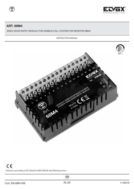
TECHNICAL SPECIFICATIONSGBThe device, appropriately integrated with colour monitor 68MV, enables the monitor to be transformed into aflush-mounting speakerphone video door entry unit. The video door entry module is simply an audio-video interfacethrough which voice and images can be made to interact; the device is provided with inputs and outputsthat enable the video door entry unit to be connected to other devices in the system (power supply unit,electric lock etc.).Figure 1 - Video door entry module type 68M4Figure 2 - Monitor type 68MV3/36
GBTECHNICAL SPECIFICATIONSType of installation.The video door entry module 68M4 (to be fitted to monitor 68MV) can only be used in <strong>Elvox</strong> Digibus digital videodoor entry systems; therefore it will be necessary to use only <strong>Elvox</strong> power supply units belonging to the <strong>Elvox</strong>Digibus range (for specifications see the relevant <strong>Elvox</strong> manuals). To create the audio function, the type of connectionto the cable riser is "4-wire" (plus power supply for the 68M4 module):- Digital line;- Digital line power supply;- Voice circuit;- Earth;- Power supply (positive);- Power supply (negative).To create the video function (integrated with the audio part), a video camera must be installed on the speechunit and therefore the video connection must be wired to the cable riser:- Video signal.- Video signal earth.The <strong>Elvox</strong> Digibus system enables the construction of systems with digital identification of the devices and controls.Depending on the configuration of the system, each of the connected devices is assigned a 4 or 8-digitnumerical code (which must be unique) and is able to receive and send data packets containing all the informationrelated to the management of the <strong>com</strong>munication; each data packet consists of the ID of the destinationdevice and the <strong>com</strong>mand which the device must execute.All the control operations typical of a video door entry system such as, for instance, calls, electric door lockrelease, stair light activation, etc., are therefore coded. However the sound for voice <strong>com</strong>munication and thevideo signal for viewing images are signals that remain analogue.As regards the type of cables to use for connection between the system <strong>com</strong>ponents, both to the riser and tothe speech unit, it is re<strong>com</strong>mended to refer to the following table and the diagrams illustrated in the chapter"INSTALLATION DIAGRAMS AND EXAMPLES":<strong>MI</strong>NIMUM CONDUCTOR CROSS-SECTION (mm 2 )TER<strong>MI</strong>NALS Up to 50 m Up to 100 m Up to 200 m4 - 5 - 9 - 10 0,75 mm 2 1 mm 2 1,5 mm 2-, +, LOCK 1 mm 2 1,5 mm 2 2,5 mm 2OTHERS 0,5 mm 2 0,75 mm 2 1,5 mm 2VIDEO:75 ohm coaxial cable (type RG59) or RG11 with double insulation4/36
TECHNICAL SPECIFICATIONSGBAdvantages of the <strong>Elvox</strong> Digibus system.One of the advantages offered by the Digibus system <strong>com</strong>pared to the conventional analogue video door entrysystem (8 + n wires), is that the call wire on the riser side for each single indoor station is no longer necessary(whereas it is necessary in the conventional analogue system). Thanks to this characteristic, the system is idealfor use in systems containing a large number of indoor stations (for example large building <strong>com</strong>plexes). This isbecause it considerably simplifies wiring operations, since the number of cables always remains fixed regardlessof the number of indoor stations to be installed:- audio door entry system: 4 wires (plus 2 for powering the 68M4 module).- video door entry system: 8 wires (including the power supply to the 68M4 module).Another advantage of using the <strong>Elvox</strong> Digibus system is its extreme flexibility in the case of subsequent systemexpansion; in fact new indoor stations can be added simply with the aid of the cable riser, without having towire extra cables to the power supply unit. Lastly, the digital management of all the <strong>com</strong>mands (call ringtoneduration, type of ringtone, call time duration, answer time duration, access via password or programmed key,etc.), enables all the parameters of the devices to be programmed according to the different requirements ofeach user.Description of terminals.The video door entry module 68M4 has two types of connectors:- removable 16-pole connector: connector on the riser side for connecting the audio and video signals, powersupplies and the digital bus (fig. 3).- 30-pole PIN-STRIP connector: connector on the monitor side for hooking up video door entry module 68M4to monitor 68MV (fig. 4).Removable 16-poleconnector.30-pole PIN-STRIPconnectorFigure 3 Figure 45/36
GBTECHNICAL SPECIFICATIONSThe connector on the riser side, through which all the connections to and from the video door entry unit aremade, has 16 terminals (inputs and outputs) divided according to the functions indicated in the following table:Terminal number Type Function1 Input/Output Digital line2 Input/Output Secondary voice unit on landing panel3 Input/Output Main voice unit on riser4 - Earth5 - Digital line earth + 13.5 V d.c.6 Output Additional bell7 - Power supply (-)8 - Power supply (+)9 Input Landing call10 Output Video distributor power supply (12 V d.c.)11 Input External F1 function12 Input External F2 function13 Input Green LED "door open" signalV1 Input Coaxial video signalM - Video signal earthV3 Input Twisted pair video signalThe connector on the monitor side must be inserted in the <strong>com</strong>partment at the top on the back of monitor 68MVin correspondence with the connector marked "VIDEO DOOR ENTRY SYSTEM" (fig. 5).You are re<strong>com</strong>mended to do this without the devices being powered and making sure that, after hookingup the module to the monitor, the mechanical coupling is perfect (all the retaining flaps should bea tight fit).VIDEO DOOR ENTRYconnectorVideo door entry module 68M4Figure 5 - Connecting the video door entry module6/36
TECHNICAL SPECIFICATIONSGBInput current.The consumption of video door entry module 68M4, once inserted in monitor 68MV, depends on the operatingmode of the video door entry unit (standby, calling, red/green LED on, activation of controls, etc.).The mean input current values in the three typical operating modes are as follows:- in standby mode 15 mA 0.18W- in call mode 200 mA 3.2W- with monitor on 150 mA 3.0WNOTE: The above values are approximate.Operation of the <strong>Elvox</strong> Digibus system.The <strong>Elvox</strong> Digibus system enables digital coding of the devices and <strong>com</strong>mands that are sent to or from the externalentrance panel; the panel can be considered as the "master" device (main appliance managing <strong>com</strong>municationbetween the digital devices in the system), while every other single digital device can be consideredas "slaves" (secondary appliance that is piloted/controlled by the master).The external entrance panel is therefore essential for the operation of the Digibus system and must alwaysbe installed in the system; all the programming parameters (call time, type of ringtone, electric lock release,code numbers of the indoor stations, etc.) are set and stored (until the next programming) in the mainexternal panel (EEPROM memory).For programming the entrance panel and all the parameters related to it, see the related <strong>Elvox</strong> technical documentation.The <strong>com</strong>munication protocol used by the Digibus systems is a proprietary <strong>Elvox</strong> protocol and is “serial-like”with active level at 12 V d.c. (0 V d.c. at rest) and input current during <strong>com</strong>munication on the digital line of 25mA (current limiter on the entrance panel).The standard speed is 600 b/s which enables distances of up to several kilometres to be reached on the digitalbus.Compatible <strong>Elvox</strong> power supply units.The power supply units that can be used for installing the system are all those in the <strong>Elvox</strong> Digibus range; Inparticular the following items are re<strong>com</strong>mended:• 6941 (standard audio door entry system power supply unit)• 6948 (standard video door entry system power supply unit).• 6947 (supplementary power supply unit for monitors and call signal).• 6942 (supplementary power supply unit for entrance panels, switchboard and video distributors).For all technical specifications (supply voltage, output current, input current, description of terminals, etc.) seethe <strong>Elvox</strong> technical manuals.7/36
GBTECHNICAL SPECIFICATIONSGeneral information on the digital <strong>com</strong>mandsDigital <strong>com</strong>mands are data packets that can be sent from each digital device and that contain the information/instructionsthat enable the activation of a particular function (lock release, stair light activation, auxiliaryfunction activation, etc.) by means of an actuator. Typically in the Digibus system, the main video door entry<strong>com</strong>mands are as follows:- LOCK <strong>com</strong>mand that pilots actuator S1- CALL-F1 <strong>com</strong>mand that pilots actuator R1- CALL-F2 <strong>com</strong>mand that pilots actuator R2The actuators can be relays or voltage generators present in the power supply units and which are controlledby the master devices (panels or switchboards) on receipt of the data packet containing the <strong>com</strong>mand to actuate.In the case of the main <strong>com</strong>mands listed above (and with reference to the Digibus power supply unit 6948) theactuators are as follows:- actuator S1 Relay the contact S1 closes to 0 (ground) on receiving the <strong>com</strong>mand.It is used to open the electric lock by means of the power supply on terminals no. 15 and 0.- actuator R1 Voltage generator 12 V d.c. (max 150 mA) active on receiving the <strong>com</strong>mand.It is used to pilot an auxiliary external relay (e.g. stair light activation).- actuator R2 Voltage generator 12 V d.c. (max 150 mA) active on receiving the <strong>com</strong>mand.It is used to pilot an auxiliary external relay (e.g. supplementary sound repeater).Each individual <strong>com</strong>mand is sent by pressing a button (associated with the same <strong>com</strong>mand) on the device.Other <strong>com</strong>mands can be associated with other buttons that may be present.List of standard <strong>com</strong>mands:CALL-PANEL+TLCCALL-PANELCALL_INTERPHONELOCKCALL-F1..F8CALL-SWITCHBOARDCall from panel with activation of video camera.Call from panel without camera.Call from interphone.Lock openCall functions F1..F8.VFor further technical and installation details, see the chapter headed “FUNCTIONS OF THE VIDEO DOORENTRY UNIT” and the attached circuit diagrams “INSTALLATION DIAGRAMS AND EXAMPLES”.8/36
FUNCTIONS OF THE VIDEO DOOR ENTRY UNITGBAfter adding module 68M4, monitor 68MV be<strong>com</strong>es, to all intents and purposes, a video door entry unit. Themain function of the device is to identify, by means of <strong>com</strong>munication and image display via the audio and videochannels, people requesting access to the residence via the speech unit and, if necessary, to release the electriclock of the gate or door.The video door entry unit also enables the implementation of other functions, namely:- activation of stair lights;- self-start of the speech unit;- additional auxiliary function.All of the functions of the video door entry unit are enabled by pressing the corresponding buttons. The mainoperating statuses of the video door entry unit are as follows:- With MONITOR ON (the LCD monitor and button backlight LEDs are on).- With MONITOR OFF (the LCD monitor and button backlight LEDs are off).FEHIACBDFigure 6 - Front view of monitor 68MV.A CALL-F1 <strong>com</strong>mand button.B LOCK <strong>com</strong>mand button.C CALL-F2 or 2ndf <strong>com</strong>mand button.D Hands-free answer button.E-F Brightness control and configuration buttons.H-I Volume control, video contrast and configuration buttons.9/36
GBFUNCTIONS OF THE VIDEO DOOR ENTRY UNITThe video signal cable selector.The selector can be used to select, depending on the type of video signal used, the most appropriate modefor reducing disturbance. The selector, indicated with V1 in the figure, allows two different settings dependingon whether the video signal <strong>com</strong>ing from the speech unit is wired with a coaxial cable (polarised video signal)or, alternatively, with a twisted pair (differential video signal).Figura 7V1 in position “D” = twisted pair (connect terminals V1 and V3)V1 in position “C” (default position) = 75 Ohm coaxial cable (connect terminals V1 and M)Selector V110/36
FUNCTIONS OF THE VIDEO DOOR ENTRY UNITGBThe “Second Function” (2ndF) button and landing call type.The main <strong>com</strong>mands CALL-F1, CALL-F2 and LOCK are sent by pressing the corresponding buttons A, C andB on the monitor.The system also enables the sending of additional “auxiliary function” <strong>com</strong>mands that can be used, for instance,to control cyclical viewing of multiple internal video cameras, to release the door lock from the landingor to control other auxiliary devices such as secondary stair lighting, etc.; to be able to use these controls, itis necessary to configure button C on the monitor as a "second function" (2ndf) button.To do this you need to set selector S1, which is on the same side of module 68M4 as the PIN-STRIP connectors(see figure below), to position 2.To select the type of landing panel (either "AUDIO" landing call or "DOOR BELL" landing call), set selector S2as indicated below.Figure 8 - 2ndF button configurationS in position 1 (default position) = "C" button CALL-F2 <strong>com</strong>mand.S in position 2 = "C" button 2ndF.2ndF buttonWARNING!The setting for selector S is done at the time of installation.11/36
GBFUNCTIONS OF THE VIDEO DOOR ENTRY UNITButton 2ndF, pressed in <strong>com</strong>bination with other buttons, sends further separate supplementary <strong>com</strong>mandson the digital line ranging from CALL-F3 to CALL-F8.When button C is configured as 2ndF, the <strong>com</strong>mand - button association is as follows:LOCKCALL-F1CALL-F2CALL-F3-F4-F5CALL-F6CALL-F7CALL-F8Press button BPress button APress buttons C+APress buttons C+E (cyclic)Press buttons C+FPress buttons C+HPress buttons C+ILOCK-LANDING (analogue type <strong>com</strong>mand) Press buttons C+BNote: The <strong>com</strong>mand-button-function <strong>com</strong>binations are also given in the section "QUICK GUIDE TO USINGTHE VIDEO DOOR ENTRY UNIT". The following procedures explain how to activate the functions of the videodoor entry unit (module 68M4 integrated into monitor 68VM) once it has been connected in an ELVOX Digibusvideo door entry system.Numerical coding of the video door entry unit.The Digibus video door entry unit (type 68MV + type 68M4) in the system by means of a 4 or 8-digit numericalcode (parameter to set on the Digibus entrance panel); it is therefore necessary to program this code asfollows:12/36
FUNCTIONS OF THE VIDEO DOOR ENTRY UNITGBFigura 10Figura 11• Simultaneously press and hold all 4 buttons A, B, C and D until the red LED starts to flash (figure 10).• Release the buttons• While the LEDs are lit, press and hold button B (lock release button, figure 11) for at least 10 seconds;• The red LED on the video door entry unit lights up confirming that the device is ready to be coded.• Send a call to the video door entry unit with the desired numerical code; if you have a panel with an alphanumerickeypad, simply key in this code and send it to the device by pressing button "C" on thepanel.• The programming of the video door entry unit with the desired code is confirmed when the red LED on themonitor switches off and the entrance panel emits an audible warning.• Lastly, check that the video door entry unit answers the call (with an alphanumeric panel, key in the set codeand press button "C"on the panel).If you do not have an entrance panel with an alphanumeric keypad or single buttons, it is necessary to use thespecial <strong>Elvox</strong> programmer or a PC with serial interface and <strong>Elvox</strong> software (see the chapter “PROGRAM<strong>MI</strong>NGTHE DIGIBUS PANEL”.13/36
GBFUNCTIONS OF THE VIDEO DOOR ENTRY UNITRisposta chiamate.Answering calls. When a call is made from a speech unit (external panel or switchboard), the 68M4 devicematching the called numerical ID modulates the programmed call tone on the monitor 68MV speaker; the videodoor entry unit then emits an audible warning and, if the video signal has also been wired, the LCD monitor switcheson to show the person making the call. Since it is a speakerphone system, to answer the call and <strong>com</strong>municatewith the speech unit it is necessary to press and hold down the answer button D (fig. 6) for the entireduration of the conversation; The call activation time is set as an entrance panel parameter; these parameterscan all be set during programming of the external entrance panel (master) and involve various functions suchas timing, user recording, etc. (for the <strong>com</strong>plete list of parameters see the <strong>Elvox</strong> technical documentation relatingto the entrance panel used and also the chapter “MAIN CONFIGURATIONS”). If the monitor is interfacedwith the home automation system, it is possible to close the call voluntarily; for more details, see thechapter "INTEGRATION WITH THE HOME AUTOMATION SYSTEM".Self-start function.This function is used to activate audio and video <strong>com</strong>munication on the speech unit without a call being received;this can be useful, for instance, when the user wants to check the area outside. The self-start function activatesonly if button C is configured as 2ndF (see the section headed “The second function (2ndF) button andtype of landing call”); having done this, to activate the self-start on the external entrance panel it is necessaryto send one of the following <strong>com</strong>mands:• CALL-F3• CALL-F4• CALL-F5Pressing button E a number of times in succession (while keeping button C pressed) also cyclically sends the<strong>com</strong>mands CALL-F3, CALL-F4 and CALL-F5.If the self-start function is enabled on the entrance panel and the corresponding numerical parameter is set,on receiving the sent <strong>com</strong>mand the entrance panel self-starts on the calling video door entry unit (for panel programmingdetails relating to this function see the section headed “MAIN CONFIGURATIONS” – ProgrammingDigibus panel (basic <strong>guide</strong>)).14/36
FUNCTIONS OF THE VIDEO DOOR ENTRY UNITGB"Door Open" signal.The video door entry unit can display a "Door Open" signal by lighting up a green LED on the right-hand sideof the LCD monitor; this application is useful for preventing undesired access to the residence. The wiring toenable the function is done by using terminal 13 of the removable 16-pin connector on module 68M4; it is alsonecessary to carry a voltage of 12 V d.c. via a N.O. contact that, inserted in the lock, closes when the door isopen and, at the same time, lights up the green LED on the monitor (average additional input current 10 mA).Example of installation:“Door open” signal powered with additional ELVOX power supply unit 6582 15 VA (13.5 V d.c.).Power supplyArt. 6582MainsPRI- +U +IA B C DMonitor68MV+668M4V3MV113121110987654321S/S115/ASV123S-+Figure 12 -Connection of "door open" signalwith additional power supply unit.V 1 3 4 5 - + CLock N.O.contactThe additional power supply is typically necessary for systems in building <strong>com</strong>plexes where numerous videodoor entry units co-exist.For single residences or small apartment blocks, where up to 10 video door entry units can be installed ofwhich at most 2 in parallel, it is possible to use the auxiliary power supply output of the main power supply (e.g.6948 terminals 15 – 0 output 15 V d.c.); if there are more video door entry units it is necessary to use additionalpower supply units (<strong>Elvox</strong> 6582 15 VA 13.5 V d.c., one for every 30 additional video door entry units).15/36
GBFUNCTIONS OF THE VIDEO DOOR ENTRY UNITActivating the lock <strong>com</strong>mand.This <strong>com</strong>mand activates the lock opening relay on the door or gate that provides access to the residence. The<strong>com</strong>mand is executed by pressing button B that sends the LOCK <strong>com</strong>mand to the entrance panel which in turnactivates the lock opening relay in the power supply unit. this output can pilot electrical locks at 12 V a.c. max1 A (for example <strong>Elvox</strong> power supply unit 6948 terminals 15 – S1). For electrical locks with higher power inputs,use an external relay. The lock <strong>com</strong>mand is activated solely with the MONITOR ON (self-start or call in progress).For wiring the control, see the diagrams in the attached “INSTALLATION DIAGRAMS AND EXAMPLES”.Activating the stair light <strong>com</strong>mand.With this <strong>com</strong>mand it is possible to activate the output used to control an external relay connected to one ormore lighting fixtures. The <strong>com</strong>mand is activated by pressing button A that sends the CALL-F1 <strong>com</strong>mand tothe entrance panel which in turn activates output R1 of the power supply that can be used to enable an externalauxiliary relay (to be fitted). For loads powered at 230 V it is re<strong>com</strong>mended to use relays with 12 V d.c. or15 V a.c. with output 230 V a.c. 3 A. The stair light activation <strong>com</strong>mand is always active in both MONITOR ONand MONITOR OFF operating states.NOTES: The <strong>com</strong>mand CALL-F1 can be remoted with a N.O. push-button by using terminals 4 and 11 ofthe16-pole connector on module 68M4.Example of installation:Wiring of <strong>Elvox</strong> external relay 170/001 12 V d.c. (15 V a.c.) 230 V a.c. 3 A for switching on stair lights.V 1 3 4 5 - +MainsRelay RelayArt. 170/001 Art. 170/001Example of installation:Wiring of <strong>Elvox</strong> external relay170/001 12 V d.c. (15 V a.c.)230 V a.c. 3 A for switching onstair lights.Power supplyArt. 69481 2 3 4 5 1 2 3 4 5F1 F2To panel or switchboardFigure 13 - Connection for stair lights with load connected on relay output R1 and <strong>com</strong>mand F1.16/36
FUNCTIONS OF THE VIDEO DOOR ENTRY UNITGBActivating the Auxiliary Function.The Auxiliary Function activation <strong>com</strong>mand can be used to activate external devices or services such as, forinstance, courtesy lights, automations, etc. this is possible by hooking up a suitable external relay at 12 V d.c.or 15 V a.c. and a contact that depends on the service you want to activate.The auxiliary function is activated by pressing button C that sends the CALL-F2 <strong>com</strong>mand to the entrancepanel which in turn activates output R2 on the power supply unit that can be used to enable an external auxiliaryrelay (to be fitted).For loads powered at 230 V it is re<strong>com</strong>mended to use relays with 12 V d.c. or 15 V a.c. with output 230 V a.c.3 A.The auxiliary function activation <strong>com</strong>mand is always active in both MONITOR OFF and MONITOR ON operatingstates, provided that button C has not been configured as button 2ndf, or with the <strong>com</strong>bination ofbuttons C+A.NOTES: The <strong>com</strong>mand CALL-F2 can be remoted with a N.O. push-button by using terminals 4 and 12 ofthe16-pole connector on module 68M4.V 1 3 4 5 - +MainsRelay RelayArt. 170/001 Art. 170/001Example of installation:Wiring of <strong>Elvox</strong> external relay170/001 12 V d.c. (15 V a.c.)230 V a.c. 3 A for switching onstair lights.Power supplyArt. 69481 2 3 4 51 2 3 4 5F1 F2To panel or switchboardFigure 14 -Connection for auxiliary function with load connected on relay output R2 and <strong>com</strong>mand F2.17/36
RGBFUNCTIONS OF THE VIDEO DOOR ENTRY UNITLanding calls.Via the wiring of the dedicated terminal it is possible to differentiate the sound of a call from the button outsidethe door (for example, landing/secondary entrance, etc.) to distinguish it from a call from a speech unit.To differentiate these "landing calls", the corresponding input (terminal no. 9) is used on the 16-pin connectorof module 68M4 and the audio line dedicated to the landing call (terminal no. 2). Alternatively, this input canbe used in the “DOORBELL” configuration using a N.O. push-button connected to terminals 9 and 5 on the16-pin connector of module 68M4 and setting the correct type of landing call. For more details see the “Mainconfigurations” and “Installation examples” section.Example of installation:AUDIO configurationMONITOR CABLE RISERV 1 3 4 5 - +DOORBELL configuration75ohm V3MV11312111098765432168MV + 68M4PF68MV 68MV+ +68M468M4TransformerArt. M832PRIMains0 12KKFF2F1123456PLK- Landing buttonF- Secondary audio entrance panelF1- Speech unit type 930DPF- Push-button for landing lock releaseV 1 3 4 5 - +MONITOR CABLE RISERL- Electric lock 12V ~P- Additional lock buttonF2- Led module for entrance panel.(10 module LED max.)30 module LED with Art. M83240 module LED with Art. 832/030Figure 15 - Connection for the landing call.Figure 16 - Doorbell calls18/36
FUNCTIONS OF THE VIDEO DOOR ENTRY UNITGBInstallation of additional external bells.If it is necessary to transmit the audible call warning to different points of the system (large properties, etc.) orto boost its intensity, it is possible to install external bell repeaters. This requires the use of terminals no. 6 and5 of the removable 16-pole connector on the 68M4 module.RelayArt. 170/101Example of installation:Installation of external mechanical doorbellwith <strong>Elvox</strong> external relay 170/101and load at 230 V a.c. max 3 A.C 1 2 15 RC 3 4 5MechanicaldoorbellRelayArt. 170/101V1MV31312111098765432168MV M +6+ 68M4M19/36
GBINSTALLATION TOPOLOGYIn practice there are different installation topologies for creating video door entry systems; the type of each systemdepends on the structure of the building, the number of indoor and outdoor stations (speech units) to beinstalled and the functions to be enabled. The most frequent layouts typically contain one or more outdoor callstations (speech units) and one or more indoor response stations; the diagram with a single speech unit usesa single power supply per riser, while the installation of more than one speech unit, in addition to one powersupply per riser, has audio-video signal switch modules. The diagrams then differ according to the functionsand services required (connection of multiple video door entry units in parallel, etc.) for which specific additionalmodules must be added (for example video distributors, additional power supply units, etc.).Figures 17 and 18 show the installation diagrams for the simplest configurations:C77 D668MV + 68M4C7F7D668MV + 68M4MONITOR CABLE RISER6BA - Entrance panel type 8845, 8845/C, 8847, 8847/CB - Power supply unit type 6948C - Monitor type 6304, 6324, 6304/C , 6324/CD - Video door entry unit type 68MV + 68M4F - Distributor type 5556/004 - 5555G - Electric lock 12V~10A2GFigure 17 - Single speech unit.20/36
INSTALLATION TOPOLOGYGBMONITOR CABLE RISERCED6BFD111110AAAG2G2G2Additional entrance panelFigure 18 - Multiple speech unit.A - Entrance panel type 8845, 8845/C, 8847, 8847/CB - Power supply unit type 6948C - Relay type 170/001D - Relay type 170/051E - Transformer type M832F - Additional power supply unit Type. 6942G - Electric lock 12V~The wiring diagrams of figure 18 show a single power supply from the riser (B) in systems using the singlespeech unit (A), whereas when there are a number of outdoor sources of the audio-video signal (speech unitswith video camera and voice unit) it is necessary to add additional modules:• video switching relay (D);• additional power supply units (F);• video distributors (H)For the technical details on the possible installation topologies in both “simple” residential and in <strong>com</strong>plexbuilding structures, see the examples shown in the attached diagrams “INSTALLATION DIAGRAMS ANDEXAMPLES” or consult the <strong>Elvox</strong> Digibus technical diagrams.21/36
GBINSTALLATION TOPOLOGYMONITOR CABLE RISERMONITOR CABLE RISER106B106BA3A4I223 3I333H3G32DCE1F E C D9 9 8AA1A22I2I2IAdditional entrance panelFigure 19 - Multiple speech unitand stairway entrance panels.A, A1, A2- Entrance panel type 8845, 8845/C, 8847, 8847/CA3, A4- Entrance panel type 8845, 8845/C, 8847, 8847/Cor 8842, 8843B - Power supply unit type 6948C - Relay type 170/001D - Relay type 170/051E - Transformer type M832F - Additional power supply unit Type. 6942G - Additional power supply unit Type. 6582H - Distributor type 5556/004 - 5555I - Electric lock 12V~22/36
CONFIGURING THE VIDEO DOOR ENTRY UNITGBAll the main functions of the video door entry unit seen in the “FUNCTIONS OF THE VIDEO DOOR ENTRYU-NIT” chapter are configured using the buttons on the front of the device (see fig. 4).Depending on the monitor operating status (ON or OFF) it is possible to set and program different functionsas follows:Enabling the self-start function.To enable this function you need to configure the entrance panel so it can receive a digital self-start <strong>com</strong>mand(typically selectable from CALL-F3, CALL-F4 or CALL-F5); to enable the self-start parameter on the entrancepanel for the desired <strong>com</strong>mand, see the section “PROGRAM<strong>MI</strong>NG THE Digibus PANEL (BASIC GUIDE)”. Afterthe entrance panel has been enabled you need to set the video door entry unit so it can send the digital selfstart<strong>com</strong>mand; this can be done both with the MONITOR OFF and with the MONITOR ON:• At the time of installation, enable button C as 2ndF (second function).• Keeping button C pressed, press button E at successive intervals (press - release - press - release).In this way the <strong>com</strong>mands CALL-F3 , CALL-F4 and CALL-F5 are sent cyclically and the entrance panel selfstartson receiving the <strong>com</strong>mand programmed as the self-start <strong>com</strong>mand.If more than one video source is installed, it is helpful to run the <strong>com</strong>mand cycle so as to pass the picture betweenmultiple video cameras.WARNING! The self-start function can only be used if button C is set as 2ndF. Enabling ConversationPrivacy. In the Digibus system, Confidential Conversation is always enabled.23/36
GBCONFIGURING THE VIDEO DOOR ENTRY UNITEnabling the “User Away” function.This type of function enables the user to indicate, via the external entrance panel, his/her absence to the porterswitchboard (if applicable); it can also be used when the user is at home but does not wish to be disturbed.When this function is enabled, the video door entry unit receiving the call emits no audible warning, but sendsthe “User away” <strong>com</strong>mand to the switchboard (where applicable).To enable the User Away function, carry out the following operations with the MONITOR OFF:• Simultaneously press buttons F and I for approximately 3 sec; the red LED will start flashing.• Press button D; the red LED goes out and the function is activated.To disable the function, carry out the following operations with the MONITOR OFF:• Simultaneously press buttons E and H for approximately 3 sec; the red LED will start flashing.• Press button D; the red LED goes out and the “User Away” function is deactivated.The red LED goes out after each programming phase or after a timeout of approximately 15 sec; if the LED goesout because of a timeout it is necessary to repeat the configuration.Red LED signals.When the "User Away" function is enabled, the LED provides the following information:• LED on steady = "User Away" function enabled.• LED flashing = Call received (the LED emits up to 4 rapid flashes to distinguish up to 4 different calls).Enabling the “HANDS-FREE” functionpress H+I until the red LED flashes, press TALK-LISTEN to enable/disable.Enabling the “AUTOMATIC ANSWER" functionpress E+F until the red LED flashes, press TALK-LISTEN to enable/disable.24/36
CONFIGURING THE VIDEO DOOR ENTRY UNITGBActivating monitor switch-on for landing calls.If there is a speech unit on the landing with a video camera, the video door entry unit must be configured sothat on receiving a call the monitor switches on (besides obviously enabling the voice unit). To enable switchingon the monitor from the landing, with the MONITOR OFF, carry out the following operations:• Simultaneously press buttons F and I for approximately 3 sec; the red LED will start flashing.• Press button C; the red LED goes out and the switch-on function is activated.To disable the function, carry out the following operations with the MONITOR OFF:• Simultaneously press buttons E and H for approximately 3 sec; the red LED will start flashing.• Press button C; the red LED goes out and monitor switch-on from the landing is deactivated. The red LEDgoes out after each programming phase or after a timeout of approximately 15 sec; if the LED goes out becauseof a timeout it is necessary to repeat the configuration.Notes:• In the case of switch-on enabling, the monitor stays on for at most 60 seconds.• By default, the monitor switch-on for landing calls function is disabled.Setting the <strong>com</strong>mand associated with landing calls.To swap over the video signal from the source on the panel to an alternative source (for example a speech uniton the landing with a video camera) it is necessary to pilot a video exchange digital relay (e.g. <strong>Elvox</strong> 170F +170/051) with a specific <strong>com</strong>mand. The <strong>com</strong>mand is sent from the video door entry unit to the digital relay thatwill enable the video exchange if the call is made from the landing; the digital activation <strong>com</strong>mands that canbe used are CALL-F6, CALL-F7 or CALL-F8.To associate the desired <strong>com</strong>mand with the landing call, carry out the following procedure:• Set button C as 2ndF.• With the monitor off, simultaneously press and hold buttons H and I for at least 3 seconds; the red LED willstart flashing.• Press the <strong>com</strong>bination related to the chosen <strong>com</strong>mand (for example C + F if you want CALL-F6), the red LEDwill go out.The red LED goes out after every programming phase or after a timeout of approximately 15 seconds; if theLED goes out because of a timeout it is necessary to repeat the configuration.Note:• The <strong>com</strong>mand set by default is CALL-F6.25/36
GBCONFIGURING THE VIDEO DOOR ENTRY UNITSelecting the type of ringtone.It is possible to select the types of ringtone to <strong>com</strong>bine with the different calls that the video door entry unitcan receive:- panel calls;- landing calls.Setting the entrance panel call ringtone.The ringtone for calls from the entrance panel is selected as follows:• With the MONITOR OFF, press button E or button F for at least 3 seconds to access the list of availabletones.• Using button E or button F, scroll through the list of tones, the video door entry unit will play the related ringtoneand save it in correspondence with the input of the entrance panel call (upon saving, the red LED willlight up for a few moments).Setting the landing call ringtone.To select the type of ringtone for landing calls, perform the following steps with the MONITOR OFF:• Simultaneously press and hold buttons E and F for approximately 3 seconds to access the list of availabletones; the red LED will start flashing.• Scroll through the list of tones using button E or button F; the video door entry unit will play the correspondingringtone and save it in correspondence with the input of the landing call and the red LED will go out.The red LED goes out after each programming phase or after a timeout of approximately 15 sec; if the LED goesout because of a timeout it is necessary to repeat the configuration.Ringtone volume adjustment.The volumes of the ringtones described above are adjusted in a similar manner for all types of call (from entrancepanel or landing panel). To adjustment is made as follows with the MONITOR OFF:• Press button H for at least 3 seconds to decrease the loudness of the ringtone;• Press button I for at least 3 seconds to increase the loudness of the ringtone.Speakerphone volume adjustment.With this procedure it is possible to adjust the volume of the audio channel that is transmitted from an speechunit to the speaker of the video door entry unit.The adjustment, to be made with the MONITOR ON and keeping button D pressed, is made as follows:• Press button H to decrease the loudness;• Press button I to increase the loudness.26/36
CONFIGURING THE VIDEO DOOR ENTRY UNITGBVideo parameter adjustment.The following procedure are used to set the three parameters that control the video picture on the LCD monitor:- brightness;- controls;- colour.Setting the brightness.To set the level of brightness of the LCD monitor, carry out the following operations with the MONITOR ON:• Press button E to decrease the brightness;• Press button F to increase the brightness.Setting the contrast.To set the level of contrast of the LCD monitor, carry out the following operations with the MONITOR ON:• Press button H to decrease the contrast;• Press button I to increase the contrast.Setting the colour.The colour adjustment is made with the trimmer located in the top left corner of monitor 68MV (see figure 20).Note: The colour setting is the least critical one and has the least effect on the quality of the picture on the LCDmonitor with respect to changes in ambient light.Setting the colourFigure 20 - Colour adjustment.27/36
GBPROGRAM<strong>MI</strong>NG THE DIGIBUS ENTRANCE PANELWARNING! The following steps must be carried out after powering up the system and before programmingthe audio and video door entry units.The entrance panel parameters can be configured in three different ways:• Directly from the panel using the alphanumeric keypad or single buttons.• With <strong>Elvox</strong> programmer type 950B.• With a PC and <strong>Elvox</strong> serial interface type 6952 and <strong>Elvox</strong> “PC Digibus ANALYZER” software.This section illustrates solely the method of programming with the alphanumeric keypad on the front of the Digibuspanel; for configuration using the programmer or a PC, refer to the relevant <strong>Elvox</strong> technical documentation.To access the panel configuration menu, carry out the following operations:• Simultaneously press buttons R and 4.• Enter the password to access to programming mode; key in "0123" for the first configuration (default passwordset in the factory that must then be changed by the installer).• Press button C to confirm.It is now possible to scroll through the list of all the panel parameters and related settings; for each one of theseparameters a value can be entered that identifies the parameter and the related configuration.The set values must be within a certain range (minimum value-maximum value) as stated in the parameterstable attached to the panel technical documentation (see, for example, the “PANEL TECHNICAL PARAME-TERS” table illustrated on the following pages).• Press button C a number of times to scroll through the list of available parameters.• Using the alphanumeric keypad, enter the value related to the parameter to be set.• Press button C to confirm.• Press button R to end programming.To configure Digibus panels with no alphanumeric keypad, refer to the relevant <strong>Elvox</strong> technical documentation.28/36
EXAMPLE OF PANEL TECHNICAL PARAMETERSGBNo.Parameter1 Initialuser2 Finaluser3 Panelcode4 SumNumberAbbreviation onthe display ofthe EnglishprogrammerInitialuserFinaluserPanelcodeSumNumberMinimumvalueMaximumvalueDefault29/36Description1 99999999 1 Minimum call number (filter on codes in transitfrom terminal 6 to terminal 1).1 99999999 99999999Maximum call number (filter on codes in transitfrom terminal 6 to terminal 1).1 99999999 0 Changes call code by adding the value of thebuttons to the value entered in the parameter.It only takes effect when parameter 26 "enablingSoftware coding" is 0.0 99999999 0 Changes call code by adding the value of thebuttons to the value entered in the parameter.It only takes effect when parameter 26 "enablingSoftware coding" is 0.5 Spare Spare6 Spare .............. Spare7 Buttonsin tworows8 CodingsystemE n a b .DoubleButtonsNumberdigits9 Language LanguageEnglish10 PanelBlock11 Enablepriority12 Enablesequentiallock13 Enablevideocamera14 Enablesound atthe panel.P a n e lBlockEnablepriorityEnablelockEnab.cameraEnab.panelsound0 1 0 Indicates the type of push-button configuration:in a single row (=0) or in two rows (=1).When tochange thevalueIt is required in building<strong>com</strong>plexes.It is required in building<strong>com</strong>plexes.In systems withporter's switchboardwith multipleelectronic panels.It is optional, itpermits the valuesof all the buttonsto be translatedwithout changingthem one by one.It is to be programmedaccording tothe modules.4 8 8 Selects system with 4 or 8 digits. For systems with4-digit coding,set the value to 4.0 1 0 To be used with programmer type 950B (0= It is optional.Italian, 1 = English).0 1 0 Disables operation of the panel (0 = No, 1 = It is optional.Yes).0 4 0 Panel with priority (0 = No, 1 = Yes). Optional but only forpanels in parallel.0 4 1 Enables lock activation.0 = The lock is only activated by the audiodoor entry unit called by the correspondingpanel.1 = The lock is activated together with thatof the main panel. The panel must be inan intermediate position between themain panel and the audio door entry unit.2 = The lock is activated by a switchboardthat takes precedence over the panel.3 = Enables both points 1 and 2.4 = The lock is activated in any case evenwhen the audio door entry unit has notbeen called.6 = Function 4 + function 2.0 1 1 Indicates whether the panel has a video camera(0 = No, 1 = Yes).0 1 1 Enables repetition of the call sound at thepanel (0 = No, 1 = Yes).It is optional.It is required with panelssupplied with anindoor or outdoorvideo camera.It is optional.
GBEXAMPLE OF PANEL TECHNICAL PARAMETERSNo.Parameter15 Enable selfstart16 Enable inter<strong>com</strong>Abbreviation onthe display ofthe EnglishprogrammerEnab.Self-StartEnab. Inter<strong>com</strong>MinimumvalueMaximumvalueDefault17 Spare .............. Spare18 Button forcalls to switchboardSwitchb.Call Button30/36DescriptionWhen tochange thevalue0 7 0 Enables self-start of the video/audio door entryunit via <strong>com</strong>mands F3, F4 and F5. Add togetherthe values of F3, F4 and F5 to indicate what functionsenable self-start (0 = No, 1 = F3,2 = F4 and4 = F5). With 7=1+2+4 it self-starts with F3, F4and F5.It is optional.0 1 0 Not available. Not available.0 255 0 Assigns the button to call the switchboard, whenthe switchboard is the main one with respect tothe panel.19 Call time Call time 1 255 12 Maximum call time (in seconds times 10, 12=120seconds).20 Ringtone time Ringtonetime21 Answer time Answertime22 Function F1time23 Function F2timeFunct. 1timeFunct. 2time24 Lock time Locktime25 End-of-conversationwarningtime26 Enables pushbuttonSoftwarecoding27 Enables upwindowEnd-ofconversationwarningtimeEnab.Softwarenum.Enab.Up Window28 Spare. .............. Spare.29 Parameter reservedParam.ReservedIt is optional.It is optional.1 255 1 Time to activate the call signal (in seconds). It is optional.1 255 30 Maximum time awaiting answer (in seconds). It is required inbuilding <strong>com</strong>plexes.0 255 1 Function F1 activation time (in seconds). If set to0 activation is reduced to 0.5 sec.0 255 1 Function F2 activation time (in seconds). If set to0 activation is reduced to 0.5 sec.0 255 1 Lock activation time (in seconds). If set to 0 activationis reduced to 0.5 sec.0 255 0 End-of-conversation warning: after a call fromthe panel with priority the existing <strong>com</strong>municationreceives a cut-off warning and stops afterthe set number of seconds (0=no warning). If setto 0 activation is reduced to 0.5 sec.0 1 0 Enables coding of the push-buttons in "Software"mode. Push-button coding is to be donewith programmer type 950B.0 1 1 Enables the "initial user" - "end user" filter alsofor data passing from terminal 1 towards terminal6 of the panel (0=No, 1=Yes).0 255 1 A password enables the reserved parameters tobe viewed.Note: in the above mentioned table there is the following correspondence:F1 = CALL-F1 F3 = CALL-F3 F5 = CALL-F5 F7 = CALL-F7F2 = CALL-F2 F4 = CALL-F4 F6 = CALL-F6 F8 = CALL-F8It is optional.It is optional.It is optional.It is optional.It is optional, butmust be usedwith programmertype 950B.It is optional butonly for building<strong>com</strong>plexes.Not to be used.
INTEGRATION OF THE VIDEO DOOR ENTRY UNIT WITH THE HOME AUTOMATION SYSTEMGBMonitor 68MV is designed to be integrated with video door entry module 68M4 and control module A960which enables management of the home automation system (control of household electrical system, burglaralarm, temperature control, load control, automations, etc.) via the video door entry unit, which basically be<strong>com</strong>esan all-in-one control panel. If both modules 68M4 and A960 are inserted into monitor 68MV, the devicewill operate in home automation control mode and will switch to video door entry mode whenever there is anin<strong>com</strong>ing external call or when the user activates it via the home automation menus. Similarly for the video doorentry module, control panel module A960 must be inserted in the <strong>com</strong>partment at the bottom on the back ofmonitor 68MV in correspondence with the connector marked "CONTROL PANEL".For further technical details, see the instruction booklet for CONTROL PANEL A960.Installation diagrams and examples.The following examples give some diagrams that summarise the typical video door entry installations in theresidential sector. For the installation details see the diagrams in the following section.Table of the functions of the buttons on the Vimar flush-mount monitor in <strong>Elvox</strong> Digibus systems.Functions differ according to whether the monitor is OFF or ON, e.g. if it is in operation after an external callfrom an entrance panel, landing panel, an inter<strong>com</strong> or after a self-start.The green LED is not governed by the device, but is switched on by an external hardware collection.31/36
GBQUICK GUIDE TO USING THE VIDEO DOOR ENTRY UNITFunction table of Vimar flush-mounted monitor push-buttons in <strong>Elvox</strong> Digibus systems.There is a distinction if the monitor is OFF or ON, that it is if it is activated by an external call from entrance panel.The green LED is not controlled by the device but it is activated by means of an external hardware connection.SISTEMButtonPressedABCDE (-)F (+)H (-)I (-)E+FH+IF+IE+HH+IE+FMonitor OFFCommand F1(F2 if C+A with 2ndF on)Command CALL_AUDIO DOOR ENTRYUNIT(Landing Lock if C+B with 2ndF on)Command F2 or 2nd Function (2ndF)button if selector S1 is in pos. 2Talk-Listen functionPanel ringtone type selection(F3-F4-F5 if C+E with 2ndF on)Panel ringtone type selection(F6 if C+F with 2ndF on)Ringtone volume selection(F7 if C+H with 2ndF on)Ringtone volume selection(F8 if C+I with 2ndF on)DigibusDescription:Monitor ONCommand F1(F2 if C+A with 2ndF on)LOCK <strong>com</strong>mand(Landing Lock if C+B with 2ndF on)Command F1 or 2nd Function (2ndF)button if selector S1 is in pos. 2Talk-Listen functionBrightness control(F6 if C+F with 2ndF on)Regolazione Luminosità(F6 se C+F con 2ndF attivo)Contrast Control Speakerphone volume controlis button D is pressed(F7 if C+H with 2ndF on)Contrast control Speakerphone volume adjustmentif button D is pressed(F8 if C+I with 2ndF on)Press simultaneously for 5 seconds with the monitor OFF to enter mode for programming the RIN-GTONE FOR LANDING CALLS. The red LED starts flashing, within 15 seconds select the ringtoneusing button E or F. After programming (when button E or F has not been pressed for 5 seconds orat the end of the timeout) the LED goes out.Press simultaneously for 5 seconds with the monitor OFF to enter mode for programming for COM-MAND ASSOCIATED WITH VIDEO LANDING CALLS. The red LED starts flashing, within 15 secondsselect the <strong>com</strong>mand associated with the call using the <strong>com</strong>bination of buttons C + F/H/I(corresponding to F6/F7/F8 with 2ndF on). After programming (when buttons E or F have not beenpressed for 5 seconds or at the end of the timeout) the LED goes out.Press simultaneously for 5 seconds with the monitor OFF, the red LED starts flashing, then:- ACTIVATE USER AWAY FUNCTION by pressing D- ACTIVATE LANDING MONITOR SWITCH-ON by pressing C.After the setting has been made or, in any case, after the 15 second timeout has elapsed, the LEDgoes out.Press simultaneously for 5 seconds with the monitor OFF, the red LED starts flashing, then:- DEACTIVATE USER AWAY FUNCTION by pressing D.- DEACTIVATE LANDING MONITOR SWITCH-ON by pressing C.After the setting has been made or after the timeout (15 seconds) has elapsed, the LED goes out.Hands-freeAutomatic answer32/36
REGOLE E CONFOR<strong>MI</strong>TÀGBInstallation regulations.Installation should be carried out observing current installation regulations for electrical systems in the countrywhere the products are installed.Regulatory <strong>com</strong>pliance.EMC DirectiveStandards EN 61000-6-1, EN 61000-6-3Note: Regulatory <strong>com</strong>pliance refers to module 68M4 when it is inserted in monitor 68MV.GlossaryEntrance panel.Set of audio and video devices that allow the user to identify the person requesting access to the residencevia the speech unit.Indoor station.Single video door entry device or audio-only door entry device that enables the user to identify the person atthe speech unit who made the call. Generally the indoor station, besides <strong>com</strong>municating with the externalpanel, can be used to carry out other operations such as lock release, turning on stair lights, etc.Speech unit (outdoor station).General term used to indicate the entrance panel or landing panel.Cable riser.Term used to indicate the set of wiring connecting the indoor stations with the power supply unit. Power supplyunit. Device that incorporates the lock mechanisms, call generators and the necessary power supply to boththe riser and the entrance panel.Landing panel.Set of audio and video devices that can be used to make a call to the indoor station(s) and which enable theperson making the call to be identified. It is generally installed for making calls from zones inside the building(landing, secondary entrances, etc.).Self-start.Optional function that allows audio and video <strong>com</strong>munication between the indoor station and entrance panelor between the indoor station and landing panel, without a call being received (from the entrance panel or landingpanel respectively).33/36
41257 8R0369CGBWIRING DIAGRAMAPARTMENT BLOCK DIGITAL VIDEO DOOR ENTRY SYSTEM WITH MONITOR AND INTERPHO-NES WITH INTERNAL DECODING.MONITOR CABLE RISERMonitorArt. 7214Art. 6604Art. 6624Art. 6614Art. 660DArt. 6704Art. 6724Art. 6714MonitorArt. 7214Art. 6604Art. 6624Art. 6614Art. 660DArt. 6704Art. 6724Art. 6714MonitorArt. 68MV+ 68M4*75ohmV3MV113121110987654321V 175ohm75ohm V3V3 75ohmMMV1V113131212111110 10998877665544332211V4V3V2V1VV-+V 134 5* *DISTRIBUTORArt. 5556/004Art. 55553 4 5- +- +MAINSPRIM2 V2 V1 M1V3MV113121110987654321POWER SUPPLYArt. 6948+I CH S F1 F2 3In each monitor insert betweenterminals V-M the 75Ohm resistor supplied* MonitorArt. 721445+Art. 6604Art. 6624Art. 6614Art. 660DArt. 6704Art. 6724Art. 6714MonitorArt. 7214Art. 6604Art. 6624Art. 6614Art. 660DArt. 6704Art. 6724Art. 6714-R14R24S1 15 O*MonitorArt. 68MV + 68M4MonitorArt. 68MV + 68M4D- Video entrance panel type8845/C - 8845 - 1285D0- Video entrance panelType 8847 - 1287P- Additional lock buttonL- Electric lock 12V ~E1- Connection terminal boardE2- Electronic unitE3- Additional modules series8A...With high-resolutioncameraDO88888888*DOJ1MV134568V1M1V2SR+ICHVL4F1F2+LV1345SR+ICHDDJ1MV134568V1M1V2SR+ICHVL4F1F2+LV1345SR+ICHPNOTE:Power supply unit type 6948can be connected to up to 18monitors type 7214, 6614,661D, 6714 with the “ringtonemute” function on (red LED lit).To connect extra monitors useadditional power supply unittype 6583 or type 6947.L34/36
SAFETY INSTRUCTIONS FOR INSTALLERSGBSAFETY INSTRUCTIONS FOR INSTALLERS- Carefully read the instructions on this leaflet: they give important information on the safety, use and maintenanceof the installation.- After removing the packing, check the integrity of the set. Packing <strong>com</strong>ponents (plastic bags, expanded polystyreneetc.) are dangerous for children. Installation must be carried out according to national safety regulations.- It is convenient to fit close to the supply voltage source a proper bipolar type switch with 3 mm separation (minimum)between contacts.- Before connecting the set, ensure that the data on the label correspond to those of the mains.- Use this set only for the purposes designed, i.e.for electric door-opener systems. Any other use may be dangerous.The manufacturer is not responsible for damage caused by improper, erroneous or irrational use.- Before cleaning or maintenance, disconnect the set.- In case of failure or faulty operation, disconnect the set and do not open it.- For repairs apply only to the technical assistance centre authorized by the manufacturer.- Safety may be <strong>com</strong>promised if these instructions are disregarded.- Do not obstruct opening of ventilation or heat exit slots and do not expose the set to dripping or sprinkling of water.- <strong>Installer</strong>s must ensure that manuals with the above instructions are left on connected units after installation, forusers' information.- All items must only be used for the purposes designed.- The ominipolar switch must be easily accessed.- WARNING: to avoid the possibility of hurting yourself, this unit must be fixed to the wall according to the installationinstructions.- This leaflet must always be enclosed with the equipment.Directive 2002/96/EC (WEEE)The crossed-out wheelie bin symbol marked on the product indicates that at the end of its useful life, the productmust be handled separately from household refuse and must therefore be assigned to a differentiated collectioncentre for electrical and electronic equipment or returned to the dealer upon purchase of a new,equivalent item of equipment.The user is responsible for assigning the equipment, at the end of its life, to the appropriate collection facilities.Suitable differentiated collection, for the purpose of subsequent recycling of de<strong>com</strong>missioned equipment and environmentally<strong>com</strong>patible treatment and disposal, helps prevent potential negative effects on health and the environmentand promotes the recycling of the materials of which the product is made. For further details regarding the collectionsystems available, contact your local waste disposal service or the shop from which the equipment was purchased.Risks connected to substances considered as dangerous (WEEE).According to the WEEE Directive, substances since long usually used on electric and electronic appliances are considereddangerous for people and the environment. The adequate differentiated collection for the subsequent dispatchof the appliance for the recycling, treatment and dismantling (<strong>com</strong>patible with the environment) help to avoid possiblenegative effects on the environment and health and promote the recycling of material with which the product is<strong>com</strong>pound.35/36
FILIALI ITALIAPadovaVia A. Ferrero, 935133 PadovaTorinoStrada del Drosso, 33/810135 TorinoMilanoVia Conti Biglia, 220162 MilanoFILIALI ESTEREELVOX Austria GmbHGrabenweg 67A-6020 InnsbruckELVOX Shanghai Electronics Co.3. Floor No. 2 Bulding No. 1898 Lai Yin RoadHi-Tech Park SongJiang, Jiu Ting DistrictShanghai 201615CERT n° 9110.ELVOUNI EN ISO 9001:2008ELVOX Costruzioni elettroniche SpaVia Pontarola, 14/a - 35011 Campodarsego (PD)Tel 049 9202511 - Fax 049 9202603 - info@elvox.<strong>com</strong>Telefax Export Dept. ..39/049 9202601 - elvoxexp@elvox.<strong>com</strong>www.elvox.<strong>com</strong>