
Create successful ePaper yourself
Turn your PDF publications into a flip-book with our unique Google optimized e-Paper software.
a P P a r a t e t e i l e – g e F Ä s s e – Z u B e h Ö r<br />
Katalog Nr. 8801, Kapitel 5<br />
coMPoNeNts oF aPParatus – Vessels – accessories<br />
catalogue No. 8801, section 5<br />
É l É M e N t s D ’ a P P a r e i l s – r É c i P i e N t s – a c c e s s o i r e s<br />
catalogue No 8801, chapitre 5<br />
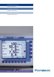
B ü c h i – t h e w a y t o g e t r e s u l t s !
Inhaltsverzeichnis<br />
seite<br />
Apparateteile<br />
5.3 Kolonne «büchiflex» DN 70-150<br />
5.4 Kolonne «<strong>KF</strong>» DN 200-600<br />
5.5 Planschliff-rohr «<strong>KF</strong>» DN 200-600<br />
5.6 rückflussteiler DN 70-150<br />
5.7 rücklaufteiler-Ventil pneumatisch<br />
5.7 rücklaufteiler-Ventil elektro-pneumatisch<br />
5.8 tragrost DN 70-600<br />
5.9 Füllkörperfänger DN 70-150<br />
5.9 Füllkörperfänger DN 200-600<br />
5.10 leittrichter «büchiflex» DN 70-150<br />
5.10 leittrichter «<strong>KF</strong>» DN 80-600<br />
5.11 Filterplatte DN 80-200<br />
5.12 raschig-ringe<br />
5.12 NoValoX “ -sattelkörper<br />
5.13 Pall ® -ringe<br />
5.13 ceraDur ® -Packung<br />
5.15 abschlusshaube DN 200-600<br />
5.17 reduktion «<strong>KF</strong>» DN 200-600<br />
5.19 thermometerschutzrohr<br />
5.20<br />
Abscheider<br />
Phasenabscheider 0,5–3 liter<br />
5.21 Phasenabscheider liegend 6–75 liter<br />
5.22 schwenksiphon DN 15-25<br />
5.22 siphon DN 25-50<br />
5.23 abscheider 5–15 liter<br />
5.24 Zyklon DN 100-300<br />
Gefässe<br />
5.25 Vorlagenrundkolben standard 6–100 liter<br />
5.27 rundkolben 6–100 liter<br />
5.29 rundkolben 200 liter<br />
5.30 rK-t rundkolben mit temperiermantel10–20 liter<br />
5.32 Zr-gefäss 5–200 liter<br />
5.33 Zr-gefäss 5–200 liter graduiert<br />
5.34 Zr-gefäss 200–400 liter<br />
5.35 Zr-t gefäss mit temperiermantel 5–100 liter<br />
5.37 Zhr-t gefäss mit temperiermantel 15 –100 liter<br />
5.39 Zr-haube für Zulauf-/Vorlagengefäss<br />
DN 200-600<br />
5.40 haube für rührgefäss DN 200-600<br />
5.41 haube DN 200-600<br />
5.43 haube für reaktionskessel DN 300-400<br />
5.44 Blindverschluss «<strong>KF</strong>» DN 15-600<br />
5.45 ausführgefässe 30–200 liter<br />
5.47 Filter Nutschen 10–50 liter<br />
5.48 Filter Nutschen 150–300 liter<br />
5.49 gaswäscher DN 70-150<br />
5.50 emaillierte reaktionskessel kpl. 15–250 liter<br />
5.53 emaillierte Bodenheizungen 15–200 liter<br />
Hinweis:<br />
alle grundlegenden Daten und angaben zum appa -<br />
rate- und rohrleitungsbau mit Borosilicatglas 3.3 sind<br />
im Kapitel 2 des Kataloges Nr. 8801 enthalten.<br />
Dort finden sie detaillierte aussagen über:<br />
• werkstoffeigenschaften<br />
• einsatzmöglichkeiten<br />
• «büchiglas»-Verbindungssysteme<br />
• Montage und inbetriebnahme<br />
• sicherheitsbestimmungen im apparate- und rohr -<br />
leitungsbau mit Borosilicatglas 3.3.<br />
Bitte geben Sie bei Ihrer Bestellung immer die vollstän dige<br />
Bestell-Nummer an, um Rückfragen und Liefer verzöge rungen<br />
zu vermeiden!<br />
«büchiflex» und «chemreaktor» sind Markennamen<br />
von <strong>Büchi</strong> ag, uster.<br />
2012
2012<br />
Table of contents Table des matières<br />
Page<br />
Apparatus components<br />
5.3 column «büchiflex» DN 70-150<br />
5.4 column «<strong>KF</strong>» DN 200-600<br />
5.5 Plane joint tube «<strong>KF</strong>» DN 200-600<br />
5.6 reflux divider DN 70-150<br />
5.7 Pneumatic reflux divider valve<br />
5.7 electro-pneumatic reflux divider valve<br />
5.8 Packing support DN 70-600<br />
5.9 Packing retaining plate DN 70-150<br />
5.9 Packing retaining plate DN 200-600<br />
5.10 redistributor «büchiflex» DN 70-150<br />
5.10 redistributor «<strong>KF</strong>» DN 80-600<br />
5.11 Filter plate DN 80-200<br />
5.12 raschig rings<br />
5.12 NoValoX “ saddle packings<br />
5.13 Pall ® -rings<br />
5.13 ceraDur ® -packing<br />
5.15 terminal cover DN 200-600<br />
5.17 reducer «<strong>KF</strong>» DN 200-600<br />
5.19 thermometer pocket<br />
Separators<br />
5.20 Phase separator 0,5–3 liters<br />
5.21 horizontal phase separator 6–75 liters<br />
5.22 swing siphon DN 15-25<br />
5.22 siphon DN 25-50<br />
5.23 separator 5–15 liters<br />
5.24 cyclone DN 100-300<br />
Vessels<br />
5.25 receiver round flask standard 6–100 liters<br />
5.27 round flask 6–100 litres<br />
5.29 round flask 200 litres<br />
5.30 round flask rK-t with heating jacket 10–20 liters<br />
5.32 Vessel Zr 5–200 liters<br />
5.33 Vessel Zr 5–200 liters graduated<br />
5.34 Vessel Zr 200–400 liters<br />
5.35 Vessel Zr-t, 5–100 liters with heating jacket<br />
5.37 Vessel Zhr-t with heating jacket 15–100 liters<br />
5.39 cover dome for feed-/receiver vessel<br />
DN 200-600<br />
5.40 cover dome for mixing vessel DN 200-600<br />
5.41 cover DN 200-600<br />
5.43 cover dome for reactor vessel DN 300-400<br />
5.44 Plug «<strong>KF</strong>» DN 15-600<br />
5.45 Mixing vessels 30–200 liters<br />
5.47 Nutsch Filter 10–50 liters<br />
5.48 Nutsch Filter 150–300 liters<br />
5.49 gas scrubber DN 70-150<br />
5.50 reactions vessel complete<br />
5.53 glass lined stell bottom heating section 15–200 liters<br />
Note:<br />
all basic data and information relating to borosilicate<br />
glass 3.3 apparatus and piping construction are con -<br />
t ained in section 2 of cataloge No. 8801.<br />
there you will find detailed information concerning:<br />
• Properties of materials<br />
• applications<br />
• «büchiglas» connecting systems<br />
• assembly and start-up<br />
• safety regulations pertaining to the construction<br />
of apparatus and piping systems with borosilicate<br />
glass 3.3<br />
Please state the complete order number when ordering to avoid<br />
unnecessary queries and delivery delays!<br />
«büchiflex» and «chemreactor» are trademarks<br />
of <strong>Büchi</strong> ag, uster.<br />
Page<br />
Eléments d’appareil<br />
5.3 colonne «büchiflex» DN 70-150<br />
5.4 colonne «<strong>KF</strong>» DN 200-600<br />
5.5 conduite à rodage plan «<strong>KF</strong>» DN 200-600<br />
5.6 tête de reflux DN 70-150<br />
5.7 Vanne pour tête de reflux pneumatique<br />
5.7 Vanne pour tête de reflux électro-pneumatique<br />
5.8 grille portante DN 70-600<br />
5.9 Plaque de maintien des garnissages DN 70-150<br />
5.9 Plaque de maintien des garnissages DN 200-600<br />
5.10 Distributeur «büchiflex» DN 70-150<br />
5.10 entonnoir «<strong>KF</strong>» DN 80-600<br />
5.11 Plaque filtrante DN 80-200<br />
5.12 anneaux raschig<br />
5.12 selles de NoValoX “<br />
5.13 anneaux Pall ®<br />
5.13 garnissage ceraDur ®<br />
5.15 cloche terminale DN 200-600<br />
5.17 réduction «<strong>KF</strong>» DN 200-600<br />
5.19 tube protecteur<br />
Séparateurs<br />
5.20 séparateur de phase 0,5–3 litres<br />
5.21 séparateur de phase horizontal 6–75 litres<br />
5.22 siphon basculant DN 15-25<br />
5.22 siphon DN 25-50<br />
5.23 séparateur 5–15 litres<br />
5.24 cyclone DN 100-300<br />
Récipients<br />
5.25 recettes ballons ronds standard 6–100 litres<br />
5.27 Ballon rond 6–100 litres<br />
5.29 Ballons ronds 200 litres<br />
5.30 Ballon rond rK-t avec double enveloppe<br />
5.32 récipient Zr 5–200 litres<br />
5.33 récipient Zr 5–200 litres gradué<br />
5.34 récipient Zr 200–400 litres<br />
5.35 récipient cylindrique Zr-t 5–100 litres,<br />
double enveloppe<br />
5.37 récipient cylindrique Zhr-t,<br />
15–100 litres double enveloppe<br />
5.39 Dôme en verre pour récipient DN 200-600<br />
5.40 Dôme en verre pour récipient avec agitation<br />
DN 200-600<br />
5.41 couvercle DN 200-600<br />
5.43 Dôme en verre pour réacteurs en DN 300-400<br />
5.44 Fermeture dissimulée «<strong>KF</strong>» DN 15-600<br />
5.45 récipients avec agitation 30–200 litres<br />
5.47 Filtres Nutsch 10–50 litres<br />
5.48 Filtres Nutsch 150–300 litres<br />
5.49 laveur de gaz DN 70-150<br />
5.50 cuves de réactions complète<br />
5.53 Fond de cuve émaillé 15–200 litres<br />
Remarque:<br />
toutes les données et indications fondamentales pour<br />
la construction d’appareils et de tuyauteries en verre au<br />
borosilicate 3.3 sont mentionnées dans le chapitre 2<br />
du catalogue no 8801.<br />
Vous y trouverez des indications détaillées sur:<br />
• les caractéristiques des matières<br />
• les possibilités d’utilisation<br />
• les systèmes de raccordement «büchiglas»<br />
• le montage et la mise en service<br />
• les dispositions de sécurité dans la construction d’appareils<br />
et de tuyauteries en verre au borosilicate 3.3<br />
Veuillez toujours indiquer le numéro de référence complet dans votre<br />
commande de manière à éviter des questions et retards de livraison!<br />
«büchiflex» et «chemreactor» sont des marques déposées<br />
de <strong>Büchi</strong> ag, uster.<br />
5.1
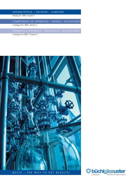
Bild 1: apparaturen und rohrleitungen<br />
von «büchiglasuster» sind seit<br />
Jahrzehnten in aller welt im einsatz.<br />
sie zeichnen sich durch<br />
hohe Betriebssicherheit bei geringstem<br />
war tungsaufwand aus.<br />
Fig.1: «büchiglasuster» equipment is<br />
used in chemical and pharmaceutical<br />
companies worldwide. they<br />
are characterized by their great<br />
operational reliability and extremely<br />
low maintenance requirement.<br />
Fig.1: les appareils de «büchiglasuster»<br />
sont utilisés dans l’industrie chimique<br />
et pharmaceutique du monde<br />
entier. ils se distinguent par leur<br />
haute sécurité d’exploitation avec<br />
des charges de maintenance minimes.<br />
5.2 2012
2012<br />
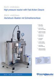
Kolonne «büchiflex» DN 70-150<br />
Column «büchiflex»<br />
Colonne «büchiflex»<br />
DN<br />
Deutsch English<br />
Français<br />
Diese Kolonnen eignen sich zum aufnehmen<br />
von Füllkörpern, aber auch von geordneten<br />
Packungen.<br />
Drei Nocken erlauben das bequeme einfahren<br />
und auflegen des tragrostes. innerhalb<br />
der in der tabelle aufgeführten minimalen<br />
und maximalen herstellungslängen<br />
kann die länge (Mass l) den jeweiligen<br />
Bedürfnissen angepasst werden. Die<br />
art.-Nr. ist dabei mit der gewünschten<br />
länge in mm gemäss Bestellbeispiel zu ergänzen.<br />
Die Vorzugslängen betragen pro Durchmesser:<br />
1000 und 1500 mm.<br />
Schliffarten<br />
1 = «büchiflex»-Kugel (1)<br />
2 = «büchiflex»-Pfanne (2)<br />
l min. l max. l 1 art.-Nr.<br />
[mm] [mm] [mm] art. No./No art.<br />
70 300 3000 60 15.01070. ....<br />
100 300 3000 70 15.01100. ....<br />
150 400 3000 80 15.01150. ....<br />
Bestellbeispiel:<br />
Ordering example:<br />
Exemple de commande:<br />
15 01100 1500<br />
• l = 1500 mm<br />
Kolonne «büchiflex» DN 100<br />
• column «büchiflex» DN 100<br />
colonne «büchiflex» DN 100<br />
• 15. … = blank/plain/nue<br />
(16.… = beschichtet/coated/revêtue)<br />
these columns are designed to be filled<br />
with loose packing material or structured<br />
packings. three studs allow for easy installation<br />
and support of the packing retaining<br />
plate. any length (l), within the maximum<br />
and minimum manufacturing range<br />
listed in the table is available in order to<br />
suit a particular application. add the required<br />
length in mm to the order number<br />
as shown in the ordering example. Preferred<br />
lengths are 1000 and 1500mm.<br />
Types of grinding<br />
1 = «büchiflex» ball (1)<br />
2 = «büchiflex» socket (2)<br />
B<br />
A<br />
DN<br />
DN<br />
L1<br />
L<br />
ces colonnes sont adaptées pour recevoir<br />
des garnissages en vrac ou des garnissages<br />
structurés. trois bourrelets permettent<br />
la mise en place du support de garnissage.<br />
la longueur (l) est à définir dans les limites<br />
minimales ou maximales (l) selon le<br />
tableau. le numéro d’article est à compléter<br />
avec la longueur (en mm) de la colonne<br />
désirée (voire exemple). longueur des<br />
séries préférentielles pour chaque diamètre:<br />
1000 et 1500mm.<br />
Genres de rodage<br />
1 = rodage mâle «büchiflex» (1)<br />
2 = rodage femelle «büchiflex» (2)<br />
5.3
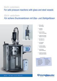
Kolonne «<strong>KF</strong>» DN 200-600<br />
Column «<strong>KF</strong>»<br />
Colonne «<strong>KF</strong>»<br />
DN l ød l min. l max. h x Bestell-Nr.<br />
[mm] [mm] [mm] [mm] [mm] [dm 3 ] art. No./No art.<br />
200 1000 150 500 2000 70 29 15.03200.1000<br />
200 1500 150 500 2000 70 45 15.03200.1500<br />
300 1000 200 500 2000 100 63 15.03300.1000<br />
300 1500 200 500 2000 100 100 15.03300.1500<br />
400 1000 275 500 1500 130 113 15.03400.1000<br />
400 1500 275 500 1500 130 175 15.03400.1500<br />
450 1000 300 500 1500 130 151 15.03450.1000<br />
450 1500 300 500 1500 130 225 15.03450.1500<br />
600 1000 420 500 1500 135 225 15.03600.1000<br />
600 1500 420 500 1500 135 365 15.03600.1500<br />
x = Füllvolumen/filling volume/volume de remplissage<br />
Bestellbeispiel:<br />
Ordering example:<br />
Exemple de commande:<br />
15 03400 1200<br />
sonderlänge l = 1200 mm<br />
• Non-standard length l = 1200 mm<br />
longueur spéciale l = 1200 mm<br />
Kolonne «<strong>KF</strong>» DN 400<br />
• Plane joint tube «<strong>KF</strong>» DN 400<br />
conduite à radage plan «<strong>KF</strong>» DN 400<br />
• 15. … = blank/plain/nue<br />
(16.… = beschichtet/coated/revêtue)<br />
Deutsch English<br />
Français<br />
Von DN 200–600 werden Kolonnen mit<br />
<strong>KF</strong>-Planschliffen ausgerüstet. ein eingeschmolzener<br />
tragring, der gleichzeitig<br />
als leittrichter dient, ermöglicht das auflegen<br />
eines tragrostes. Die Baulänge<br />
(Mass l) beträgt für alle Nennweiten<br />
1000 respektiv 1500 mm. sonderlängen<br />
innerhalb der auf der tabelle aufgeführten<br />
minimalen und maximalen herstellungslängen<br />
sind möglich.<br />
Die Bestell-Nr. ist dabei mit der gewünschten<br />
länge in mm gemäss Bestellbeispiel<br />
zu ergänzen.<br />
Schliffart<br />
4 = <strong>KF</strong>-Planschliff<br />
DN 200 to 600 columns are delivered<br />
with <strong>KF</strong> – plane joint connections. the fused-in<br />
support ring serves to allocate the<br />
packing retaining plate and acts as a redistributor<br />
at the same time. the lengths<br />
(dimension l) for all diameters are 1000<br />
mm and 1500 mm. special lengths within<br />
the maximum and minimum lengths indicated<br />
in the table can be supplied.<br />
add the required length in mm to the order<br />
number as shown in the ordering<br />
example.<br />
Grinding types<br />
4 = <strong>KF</strong> plane joint<br />
5.4 2012<br />
DN<br />
ød<br />
h<br />
L<br />
Des DN 200 à 600, les colonnes sont<br />
équipées de rodages plans <strong>KF</strong>. un anneau<br />
porteur scellé qui fait simultanément fonction<br />
d’entonnoir permet de placer une grille<br />
portante. la longueur standard pour<br />
chaque diamètre nominal est de 1000 ou<br />
1500 mm. Dans le cadre des longueurs<br />
mini et maxi du tableau il est possible<br />
d’obtenir des longueurs spéciales.<br />
le numéro d’article doit alors être complété<br />
selon l’exemple de commande par la<br />
longueur souhaitée en mm.<br />
Genres de rodage<br />
4 = rodage plan <strong>KF</strong>
2012<br />
Planschliff-Rohr «<strong>KF</strong>» DN 200-600<br />
Plane joint tube «<strong>KF</strong>»<br />
Conduite à rodage plan «<strong>KF</strong>»<br />
DN<br />
Bestellbeispiel für Sonderlänge:<br />
Ordering example for non-standard length:<br />
Exemple de commande de longueurs spéciales:<br />
15 04400 0400<br />
sonderlänge l = 400 mm<br />
• Non-standard length l = 400 mm<br />
longueur spéciale l = 400 mm<br />
Planschliff-rohr «<strong>KF</strong>» DN 400<br />
• Plane joint tube «<strong>KF</strong>» DN 400<br />
conduite à radage plan «<strong>KF</strong>» DN 400<br />
• 15. … = blank/plain/nue<br />
(16.… = beschichtet/coated/revêtue)<br />
Deutsch English<br />
Français<br />
Die Baulänge (Mass l) beträgt für alle<br />
Nennweiten 500, 1000 und 1500 mm.<br />
sonderlängen innerhalb der auf der<br />
tabelle aufgeführten minimalen und maximalen<br />
herstellungslängen sind möglich.<br />
Die Bestell-Nr. ist dabei mit der gewünschten<br />
länge in mm gemäss Bestellbeispiel<br />
zu ergänzen.<br />
Schliffart<br />
4 = <strong>KF</strong>-Planschliff<br />
l l min. l max. Bestell-Nr.<br />
[mm] [mm] [mm] art. No./No art.<br />
200 500 150 2000 15.04200.0500<br />
200 1000 150 2000 15.04200.1000<br />
200 1500 150 2000 15.04200.1500<br />
300 500 200 2000 15.04300.0500<br />
300 1000 200 2000 15.04300.1000<br />
300 1500 200 2000 15.04300.1500<br />
400 500 250 1500 15.04400.0500<br />
400 1000 250 1500 15.04400.1000<br />
400 1500 250 1500 15.04400.1500<br />
450 500 300 1500 15.04450.0500<br />
450 1000 300 1500 15.04450.1000<br />
450 1500 300 1500 15.04450.1500<br />
600 500 350 1500 15.04600.0500<br />
600 1000 350 1500 15.04600.1000<br />
600 1500 350 1500 15.04600.1500<br />
the lengths (dimension l) for all diameters<br />
are 500, 1000 and 1500 mm. special<br />
lengths between the maximum and minimum<br />
lengths in the table can be supplied.<br />
add the required length in mm to the order<br />
number as shown in the ordering<br />
example.<br />
Grinding types<br />
4 = <strong>KF</strong> plane joint<br />
DN L<br />
la longueur de construction (cote l) pour<br />
tous les diamètres est de 500, 1000 et<br />
1500 mm. Dans le cadre des longueurs<br />
mini et maxi du tableau il est possible<br />
d’obtenir des longueurs spéciales.<br />
le no d’article doit alors être complété<br />
dans la longueur souhaitée en mm selon<br />
l’exemple de commande.<br />
Genres de rodage<br />
4 = rodage plan <strong>KF</strong><br />
5.5
Rückflussteiler DN 70-150<br />
Reflux divider<br />
Tête de reflux<br />
DN DN 1 DN 2 l l 1 l 2 Bestell-Nr.<br />
[mm] [mm] [mm] [mm] art. No./No art.<br />
70 25 25 300 60 125 15.02500. 0000<br />
100 25 25 300 60 135 15.02510. 0000<br />
150 25 25 450 80 180 15.02520. 0000<br />
Deutsch English<br />
Français<br />
Dieses Bauteil mit «büchiflex»-anschlussstutzen<br />
wird in glaskolonnen zur entnahme<br />
des Destillats eingesetzt. Die ableitung<br />
erfolgt durch den entnahmestutzen DN 1.<br />
Bei Drosselung eines in die ablaufeinleitung<br />
eingebauten absperrorgans staut<br />
sich das Destillat und läuft durch ein höher<br />
angesetztes rücklaufrohr zentral auf die<br />
Kolonne zurück. Der stutzen DN 2 dient<br />
zum einbau eines thermometers.<br />
Schliffarten<br />
1 = «büchiflex»-Kugel<br />
2 = «büchiflex»-Pfanne<br />
Rücklaufteiler DN 70-150<br />
Reflux divider<br />
Tête de reflux<br />
this component with «büchiflex» connections<br />
is used in glass columns for the recovery<br />
of the distillate. the distillate is drained<br />
through the DN 1 outlet connection.<br />
closing a shut-off valve in the drain lines<br />
stems the flow of the distillate so that it returns<br />
to the column via a tube located<br />
higher up in the center of the column. the<br />
DN 2 socket serves to accommodate a<br />
thermometer.<br />
Types of grinding<br />
1 = «büchiflex» ball<br />
2 = «büchiflex» socket<br />
Deutsch English<br />
Français<br />
in rektifizierkolonnen werden zum aufteilen<br />
des Destillats in rücklauf und ablauf<br />
rücklaufteiler eingesetzt. Das Destillat<br />
wird mit dem pneumatischen oder wahlweise<br />
elektro-pneumatisch betätigten<br />
rücklaufteiler-Ventil im gewünschten rücklaufverhältnis<br />
in die Kolonne zurückgeführt.<br />
Die steuerung des rücklaufteiler-<br />
Ventils erfolgt durch pneumatische oder<br />
elektrische Zeitschaltgeräte.<br />
reflux dividers are set in rectification<br />
columns to divide the distillate into reflux<br />
and product withdrawal. the distillate is<br />
returned to the column in the desired<br />
reflux ratio, controlled by the pneumatic<br />
(option: electropneumatic) reflux divider<br />
valve. the reflux divider valve is controlled<br />
by a pneumatic or electric timer.<br />
ce composant avec des raccords «büchiflex»<br />
est utilisé dans les colonnes de verre<br />
pour prélever le distillat. la dérivation est<br />
assurée par le raccord de prélèvement<br />
DN 1. en cas d’étranglement par une vanne<br />
d’arrêt, incorporée dans la conduite<br />
d’écoulement, le distillat s’accumule et retourne<br />
à la colonne par un tuyau de retour<br />
placé en hauteur centralement sur la colonne.<br />
le raccord DN 2 sert au montage<br />
d’un thermomètre.<br />
Genres de rodage<br />
1 = rodage mâle «büchiflex»<br />
2 = rodage femelle «büchiflex»<br />
5.6 2012<br />
15 o<br />
15 o<br />
L1<br />
DN25<br />
H<br />
B<br />
DN2<br />
DN1<br />
DN<br />
DN<br />
L2<br />
85 o<br />
DN25<br />
DN25<br />
DN<br />
DN<br />
A<br />
L<br />
têtes de reflux sont utilisées dans les<br />
colonnes de rectification pour répartir le<br />
distillat dans la colonne et le prélèvement.<br />
le distillat est ramené dans la colonne<br />
dans la proportion de retour souhaitée<br />
par la vanne de tête de reflux à commande<br />
pneumatique (ou électropneumatique<br />
en option). la commande de la vanne de<br />
tête de reflux est assurée par des appareils<br />
à commande temporisée pneumatique<br />
ou électrique.<br />
L<br />
D<br />
U<br />
DN25<br />
h
2012<br />
DN h h l Bestell-Nr. Bestell-Nr.<br />
[mm] [mm] [mm] art. No./No art. art. No./No art.<br />
70 375 173 479 15.02650. 0000 15.02680. 0000<br />
100 400 181 489 15.02660. 0000 15.02690. 0000<br />
150 525 200 529 15.02670. 0000 15.02700. 0000<br />
a = rücklaufteiler-Ventil pneumatisch/Pneumatic reflux divider valve/Vanne pour tête de reflux pneumatique<br />
B = rücklaufteiler-Ventil elektro-pneumatisch/electro-pneumatic reflux divider valve/Vanne pour tête de reflux électro-pneumatique<br />
Rücklaufteiler-Ventil pneumatisch<br />
Pneumatic reflux divider valve<br />
Vanne pour tête de reflux pneumatique<br />
Bestell-Nr.<br />
art. No./No art.<br />
15.02710. 0000<br />
Deutsch English<br />
Français<br />
Dieses Bauteil ist Bestandteil vom rücklaufteiler<br />
DN 70-150. Dieses kompakte<br />
auf/Zu-Ventil ist mit einem doppelwirkenden<br />
pneumatischen antrieb ausgerüstet.<br />
es eignet sich für die regelung von Flüssigkeitsströmen.<br />
Die steuerung erfolgt mit<br />
einem pneumatischen Zeitschaltgerät. Die<br />
stopfbuchslose Konstruktion garantiert einen<br />
wartungsfreien Betrieb und eine hohe<br />
einsatzdauer. Durchfliessende Medien<br />
kommen nur mit Borosilicatglas 3.3 und<br />
dem PtFe-Faltenbalg in Berührung.<br />
this component is part of the DN 70-150<br />
reflux divider. the compact shut-off valve<br />
is equipped with a double-acting pneumatic<br />
actuator and is suitable for controlling<br />
liquid flows. it is actuated by a pneumatic<br />
timer. the stuffing-box-free design guarantees<br />
zero-maintenance operation and a<br />
high-duty-cycle. the flow medium only<br />
contacts borosilicate glass 3.3 and the<br />
PtFe bellows.<br />
Rücklaufteiler-Ventil elektro-pneumatisch<br />
Electro-pneumatic reflux divider valve<br />
Vanne pour tête de reflux électro-pneumatique<br />
Bestell-Nr.<br />
art. No./No art.<br />
15.02720. 0000<br />
Deutsch English<br />
Français<br />
Dieses Bauteil ist Bestandteil vom rücklaufteiler<br />
DN 70-150. Dieses kompakte<br />
auf/Zu-Ventil ist mit einem doppelwirkenden<br />
pneumatischen antrieb und einem exgeschützten<br />
5/2-wege-Magnetventil ausgerüstet.<br />
es eignet sich für die regelung<br />
von Flüssigkeitsströmen. Dei steuerung erfolgt<br />
mit einem elektrischen Zeitschaltgerät.<br />
Die stopfbuchslose Konstruktion ga -<br />
rantiert einen wartungsfreien Betrieb und<br />
eine hohe einsatzdauer. Durchfliessende<br />
Medien kommen nur mit Borosilicatglas<br />
3.3 und dem PtFe-Faltenbalg in Berührung.<br />
D<br />
this component is part of the DN 70-150<br />
reflux divider. the compact shut-off valve<br />
is equipped with a double-acting pneumatic<br />
actuator and an explosion proof 5/2<br />
way solenoid valve. it is suitable for controlling<br />
liquid flows and is actuated by an<br />
electric timer. the stuffing-box-free design<br />
guarantees zero-maintenance operation<br />
and a high-duty-cycle. the flow medium<br />
only contacts borosilicate glass 3.3 and<br />
the PtFe bellows.<br />
ausf./type/exéc.a ausf./type/exéc.B<br />
A<br />
DN25/2<br />
120<br />
50<br />
100<br />
85 o<br />
C<br />
DN25/1<br />
DN25/1<br />
ce composant fait partie de la tête de reflux<br />
DN 70-150. cette vanne d’ouverture<br />
– fermeture compacte est équipée d’un<br />
entraînement pneumatique à double effet.<br />
il convient pour la régulation de débit de<br />
liquides. la commande intervient par un<br />
appareil à commande pneumatique temporisée.<br />
la construction sans presse-étoupe<br />
garantit un fonctionnement sans entretien<br />
et une grande durée d’utilisation. les<br />
produits qui s’écoulent n’entrent en contact<br />
qu’avec le verre au borosilicate 3.3 et<br />
le soufflet en PtFe.<br />
A<br />
DN25/2<br />
143<br />
50<br />
85 o<br />
100 100<br />
C<br />
D<br />
U<br />
DN25/1<br />
ce composant fait partie de la tête de reflux<br />
DN 70-150.cette vanne d’ouverturefermeture<br />
compacte est équipée d’un entraînement<br />
pneumatique à double effet et<br />
d’une électrovanne antidéflagrante à<br />
5/2 voies. il convient pour la régulation<br />
de débit de liquides. la commande intervient<br />
par un appareil à commande pneumatique<br />
temporisée. la construction sans<br />
presse-étoupe garantit un fonctionnement<br />
sans entretien et une grande durée d’utilisation.<br />
85 o<br />
100<br />
85 o<br />
DN25/1<br />
B<br />
B<br />
5.7
Tragrost DN 70-600<br />
Packing support<br />
Grille portante<br />
02<br />
01<br />
øD<br />
DN70-200<br />
Deutsch English<br />
Français<br />
tragroste aus Borosilicatglas (Pos.01) werden<br />
in Füllkörperkolonnen nach seite 5.3<br />
und 5.4 eingebaut.<br />
angaben über die tragfähigkeit der<br />
tragroste, die minimale grösse der zu<br />
verwendenden Füllkörper sowie den<br />
freien Querschnitt, sind der tabelle zu<br />
entnehmen.<br />
Der unter dem tragrost angeordnete<br />
PtFe-ring gehört zum lieferumfang<br />
(Pos. 02).<br />
h<br />
X ØD h N o FQ Bestell-Nr.<br />
[DN] [mm] [mm] [kg] [mm] [%] art. No./No art.<br />
70 68 22 20 8 45 15.25000. 0000<br />
100 95 22 30 10 45 15.25010. 0000<br />
150 142 30 60 15 50 15.25020. 0000<br />
200 192 30 90 20 50 15.25030. 0000<br />
300 275 50 160 25 55 15.25040. 0000<br />
400 370 50 250 30 62 15.25050. 0000<br />
450 430 50 300 35 64 15.25060. 0000<br />
600 575 70 470 35 60 15.25070. 0000<br />
X = zu Kolonnen DN/for columns DN/pour les colonnes DN<br />
N = tragfähigkeit/carrying capacity/capacité de charge<br />
o = min. grösse der Füllkörper/minimum size of packings/grandeur minimale des<br />
corps de remplissage<br />
PQ = Freier Querschnitt/unobstructed passage/passage libre<br />
Borosilicate glass packing supports<br />
(pos.01) are installed in packing columns<br />
accord ing to pages 5.3 and 5.4.<br />
see the table for details of the carrying capacity<br />
of the packing supports, the minimum<br />
size of the packings to be used as<br />
well as the unobstructed passage.<br />
the PtFe ring arranged under the packing<br />
support is included in the delivery (item<br />
02).<br />
DN300-600<br />
les grilles portantes en verre au boro -<br />
silicate (pos.01) sont montées dans des<br />
colonnes garnies, voir pages 5.3 et 5.4.<br />
les indications sur la capacité de charge<br />
de la grille portante, la grandeur mini -<br />
male des corps de garnissage à utiliser de<br />
même que la section libre sont mention -<br />
nées dans le tableau.<br />
l’anneau en PtFe disposé sous la grille<br />
portante fait partie des fournitures (pos. 02).<br />
5.8 2012<br />
øD<br />
h<br />
02<br />
01
2012<br />
Füllkörperfänger DN 70-150<br />
Packing retaining plate<br />
Plaque de maintien des garnissages<br />
DN ØD h Ød n FQ Bestell-Nr.<br />
[mm] [mm] [mm] [%] art. No./No art.<br />
50 53 5,0 7,0 21 41 15.25490. 0000<br />
70 73 5,0 8,0 37 48 15.25500. 0000<br />
100 102 5,0 8,0 85 56 15.25510. 0000<br />
150 157 5,0 8,0 199 56 15.25520. 0000<br />
n = anzahl löcher (Ød)/number of holes (diameter d)/nombre de trous (Ød)<br />
FQ = Freier Querschnitt/unobstructed passage/passage libre<br />
Deutsch English<br />
Français<br />
Füllkörperfänger aus PtFe werden in Füllkörperkolonnen<br />
mit «büchiflex»-schliffen<br />
nach seite 5.3 eingebaut. Der einbau<br />
empfiehlt sich besonders für arbeiten im<br />
Vakuum, um die Füllkörper bei Druckstössen<br />
zurückzuhalten.<br />
Füllkörperfänger DN 200-600<br />
Packing retaining plate<br />
Plaque de maintien des garnissages<br />
PtFe packing retaining plates are used in<br />
packed columns with «büchiflex» type of<br />
grinding according to page 5.3. their installation<br />
is especially recommended for<br />
vaccum processes hold the packings back<br />
in the event of pressure surges.<br />
Deutsch English<br />
Français<br />
Der einbau von PtFe-Füllkörperfängern<br />
empfiehlt sich bei Kolonnen «<strong>KF</strong>» nach<br />
seite 5.4. Die Montage erfolgt durch<br />
Zwischenspannen beim <strong>KF</strong>-Planschliff unter<br />
Verwendung einer Kragendichtung<br />
«<strong>KF</strong>-Plan».<br />
it is advisable to install PtFe packing re -<br />
taining plates in «<strong>KF</strong>» columns according<br />
to page 5.4. the retaining plate is clamped<br />
between the ground surfaces of the<br />
<strong>KF</strong> plane joint together with a «<strong>KF</strong>-plan»<br />
collar gasket.<br />
DN<br />
øD<br />
ød h<br />
les plaques de maintien de garnissages<br />
en PtFe sont montées dans les colonnes<br />
garnies, colonnes avec rodages «büchiflex»,<br />
voir page 5.3. le montage est recommandé<br />
en particulier pour process<br />
sous vide de manière à retenir le garnissage<br />
en cas de coups de bélier.<br />
d1<br />
k<br />
d<br />
d2<br />
le montage de plaques de maintien de<br />
garnissages en PtFe est recommandé dans<br />
le cas de colonnes «<strong>KF</strong>», voir page 5.4.<br />
le montage intervient par serrage intermédiaire<br />
sur le rodage <strong>KF</strong> en utilisant un joint<br />
à collerette de rodage «<strong>KF</strong>-plan».<br />
X d d 2 n d 1 n k FQ Bestell-Nr.<br />
[DN] [mm] [mm] [d 2] [mm] [d 1] [mm] [%] art. No./No art.<br />
200 315 15 109 9,5 8 280 61 15.25600. 0000<br />
300 420 20 151 9,5 12 395 67 15.25610. 0000<br />
400 515 20 271 9,5 16 495 67 15.25620. 0000<br />
450 610 20 361 9,5 16 585 70 15.25630. 0000<br />
600 735 25 367 14,0 20 710 63 15.25640. 0000<br />
n = anzahl löcher (Ød 1+ Ød 2)/number of holes (diameter d 1+diameter d 2)/nombre de trous (Ød 1+ Ød 2)<br />
FQ = Freier Querschnitt/unobstructed passage/passage libre<br />
5.9
Leittrichter «büchiflex» DN 70-150<br />
Redistributor «büchiflex»<br />
Distributeur «büchiflex»<br />
DN<br />
d 1 d 2 h FQ Bestell-Nr.<br />
[mm] [mm] [mm] [%] art. No./No art.<br />
70 84 56 3,8 64 15.25660. 0000<br />
100 115 75 7,4 56 15.25661. 0000<br />
150 172 105 7,7 49 15.25662. 0000<br />
Deutsch English<br />
Français<br />
Der einbau von PtFe-leittrichtern ist bei<br />
höheren Füllkörperkolonnen zur Vermeidung<br />
der randläufigkeit der Flüssigkeit<br />
angezeigt.<br />
Die Montage erfolgt anstelle des Dicht -<br />
rings «büchiflex».<br />
Leittrichter «<strong>KF</strong>» DN 80-600<br />
Redistributor «<strong>KF</strong>»<br />
Entonnoir «<strong>KF</strong>»<br />
DN<br />
tall packed columns require the use of<br />
PtFe redistributors to prevent the liquid<br />
from running down the column wall.<br />
redistributors are installed in lieu of «büchi -<br />
flex» sealing rings.<br />
d 1 d 2 d h FQ Bestell-Nr.<br />
[mm] [mm] [mm] [mm] [%] art. No./No art.<br />
80 96 55 3 6 47 15.25700. 0000<br />
100 116 75 3 6 59 15.25710. 0000<br />
150 169 105 4 8 49 15.25720. 0000<br />
200 220 150 4 8 56 15.25730. 0000<br />
300 320 230 5 10 58 15.25740. 0000<br />
400 435 310 5 10 60 15.25750. 0000<br />
450 492 350 5 10 60 15.25760. 0000<br />
600 645 460 5 10 58 15.25770. 0000<br />
Deutsch English<br />
Français<br />
Der einbau von PtFe-leittrichtern ist bei<br />
höheren Füllkörperkolonnen zur Vermeidung<br />
der randläufigkeit der Flüssigkeit<br />
angezeigt.<br />
Die Montage erfolgt ohne zusätzliche<br />
Dichtungen durch Zwischenspannen beim<br />
<strong>KF</strong>-Planschliff.<br />
the installation of PtFe redistributors is recommended<br />
in the case of tall packing<br />
columns to avoid the rim overflow of the<br />
washing liquid.<br />
the redistributor is installed without additional<br />
gaskets between the ground sur -<br />
faces of the <strong>KF</strong> plane joint.<br />
Pour les colonnes garnies sur une grande<br />
hauteur, il est recommandé d’utiliser des<br />
distributeurs de fluide afin d’éviter l’écoulement<br />
le long des parois. le montage est<br />
fait à la place du joint «büchiflex».<br />
le montage d’entonnoirs en PtFe est con -<br />
seillé dans le cas de colonnes garnies<br />
hautes pour éviter l’écoulement du li quide<br />
de lavage sur les bords de la colonne. le<br />
montage intervient sans joint supplémentaire<br />
par serrages intermédiaires sur le rodage<br />
plan «<strong>KF</strong>».<br />
5.10 2012<br />
h<br />
d1<br />
DN<br />
d1<br />
d2<br />
d2 h<br />
d
2012<br />
Filterplatte DN 80-200<br />
Filter plate<br />
Plaque filtrante<br />
Deutsch English<br />
Français<br />
Filterplatten aus gesintertem Borosilicatglas<br />
sind randverschmolzen und werden<br />
zwischen zwei <strong>KF</strong>-Planschliffe eingespannt.<br />
Die erforderlichen zwei Kragendichtuungen<br />
«<strong>KF</strong>» sind separat zu bestellen.<br />
es sind folgende Porositäten lieferbar:<br />
Porosität max. Porenweite µm Kenn-Nr.<br />
Porosity max. pore size µm code number<br />
Porosité largeur de pore max. µm no indice<br />
P 250 (0) 160…250 0250<br />
P 160 (1) 100…160 0160<br />
P 100 (2) 40…100 0100<br />
X d h art.-Nr.<br />
[DN] [mm] [mm] art. No./No art.<br />
80 110 11 15.26000. ....<br />
100 130 13 15.26010. ....<br />
150 185 16 15.26020. ....<br />
200 235 19 15.26030. ....<br />
Bestellbeispiel:<br />
Ordering example:<br />
Exemple de commande:<br />
15 26020 0160<br />
Porosität P 160<br />
• Porosity P 160<br />
Porosité P 160<br />
sintered borosilicate glass filter plates are<br />
h-fused and are mounted between two <strong>KF</strong><br />
plane joints. the two «<strong>KF</strong>» collar gaskets<br />
required must be ordered separately.<br />
the follwing porosities can be supplied:<br />
Filterplatte DN 150<br />
• Filter plate DN 150<br />
Plaque filtrante DN 150<br />
d<br />
h<br />
les plaques filtrantes en verre au borosilicate<br />
fritté ont leur bord fondu et sont serrées<br />
entre deux rodages plans «<strong>KF</strong>». les<br />
deux joints à collerette «<strong>KF</strong>» nécessaires<br />
doivent être commandés séparément. les<br />
porosités suivantes sont livrables:<br />
Die Bestell-Nr. wird aus der art.-Nr. und Kenn-Nr. für die<br />
gewünschte Porosität gemäss Bestellbeispiel gebildet.<br />
le numéro de commande est constitué du numéro d’article<br />
et du numéro d’indice pour la porosité souhaitée selon<br />
l’exemple de commande.<br />
the order number is formed from the article number and the<br />
code number for the desired porosity in accordance with the<br />
ordering example.<br />
X = zu <strong>KF</strong>-Planschliff/for <strong>KF</strong> plane joint/<br />
pour rodage plan <strong>KF</strong><br />
5.11
Raschig-Ringe<br />
Raschig rings<br />
Anneaux Raschig<br />
Ø x l g a FQ Bestell.-Nr.<br />
[mm] [kg/dm 3 ] [m 2 /m 3 ] [%] art. No./No art.<br />
8 x 8 0,62 630 70 15.27005. 0000<br />
10 x 10 0,54 581 75 15.27000. 0000<br />
15 x 15 0,39 392 82 15.27010. 0000<br />
20 x 20 0,28 262 87 15.27020. 0000<br />
25 x 25 0,27 184 87 15.27030. 0000<br />
30 x 30 0,20 131 87 15.27040. 0000<br />
35 x 35 0,18 112 91 15.27050. 0000<br />
40 x 40 0,16 93 92 15.27060. 0000<br />
50 x 50 0,14 83 93 15.27070. 0000<br />
g = gewicht, geschüttet/weight, bulk/poids, secoué<br />
a = austauschfläche, geschüttet/exchange area, bulk/<br />
surface d’échange secoué<br />
FQ = Freier Querschnitt/unobstructed passage/passage libre<br />
Deutsch English<br />
Français<br />
auf grund ihrer nahezu universellen Medienbeständigkeit<br />
werden raschig-ringe<br />
aus Borosilicatglas als Füllkörper in glas -<br />
kolonnen eingesetzt.<br />
«büchiglasuster» liefert 8 standardisierte<br />
grössen, um das jeweils verfahrenstypisch<br />
optimale Verhältnis zwischen Kolonnen-Nennweite<br />
und Füllkörpergrösse bzw.<br />
-oberfläche realisieren zu können.<br />
Die Bestellmenge ist in dm 3 anzugeben.<br />
NOVALOX ® -Sattelkörper<br />
NOVALOX ® saddle packings<br />
Selles de NOVALOX ®<br />
Due to their virtually unlimited corrosion<br />
resistance, borosilicate glass raschig<br />
rings can be used as packings in glass<br />
columns.<br />
«büchiglasuster» supplies 8 standard<br />
sizes to ensure the optimization of the relationship<br />
between the nominal inside di -<br />
ameter of the column and the size of the<br />
packings.<br />
ordering units are dm 3 .<br />
Keramik<br />
Ceramic<br />
grösse Céramique PVDF PFA<br />
taille Bestell-Nr. Bestell-Nr. Bestell-Nr.<br />
size art. No./No art. art. No./No art. art. No./No art.<br />
1/2" 15.27100. 0000 – –<br />
3/4" 15.27110. 0000 – –<br />
1" 15.27120. 0000 15.27220. 0000 15.27320. 0000<br />
1 1/2" 15.27130. 0000 15.27230. 0000 15.27330. 0000<br />
2" 15.27140. 0000 15.27240. 0000 15.27340. 0000<br />
en raison de leur résistance pratiquement<br />
universelle aux milieux, on utilise des an -<br />
neaux raschig en verre au borosilicate<br />
comme corps de remplissage dans les<br />
colonnes de verre. «büchiglasuster» fournit<br />
8 grandeurs standardisées pour pou voir<br />
obtenir le rapport optimal entre le diamètre<br />
nominal des colonnes et la surface ou la<br />
grandeur des corps de remplissage. la<br />
quantité commandée doit être indiquée<br />
en dm 3 .<br />
5.12 2012
2012<br />
PALL ® -Ringe<br />
PALL ® -rings<br />
Anneaux PALL ®<br />
Keramik<br />
Ceramic PVDF PFA<br />
Grösse FQ Céramique Bestell-Nr. Bestell-Nr.<br />
[mm] [%] Bestell-Nr. art. No./ art. No./<br />
art. No./No art. No art. No art.<br />
25 91 15.27400. 0000 15.27500. 0000 15.27600. 0000<br />
35 93 15.27410. 0000 15.27510. 0000 15.27610. 0000<br />
50 95 15.27420. 0000 15.27520. 0000 15.27620. 0000<br />
Deutsch English<br />
Français<br />
Die NoValoX ® und Pall ® -Füllkörper sind<br />
universell einsetzbar und sind in den<br />
werkstoffen Keramik, PVDF, PFa, PP, Pe<br />
usw. lieferbar.<br />
Die Bestellmenge ist in dm 3 anzugeben.<br />
CERADUR ® -Packung<br />
CERADUR ® -packing<br />
Garnissage CERADUR ®<br />
Pressure Drop<br />
[mbat/m]<br />
DN<br />
Dm l Bestell-Nr.<br />
[mm] [mm] art. No. / No art.<br />
70 65 170 09.02046.0000<br />
100 94 170 09.02047.0000<br />
150 148 170 09.02048.0000<br />
30<br />
20<br />
10<br />
8<br />
6<br />
4<br />
2<br />
1<br />
0.8<br />
0.6<br />
0.4<br />
0.60.8 1 2 3 4 5<br />
F factor [Pa 0.5 ]<br />
Number of Theoretical<br />
Stages [ 1 /m]<br />
5<br />
4<br />
3<br />
2<br />
1<br />
0.60.8 1 2 3 4 5<br />
F factor [Pa 0.5 ]<br />
NoValoX ® and Pall ® packings can be<br />
used for a wide range of applications.<br />
they are available in materials as ceramic,<br />
PVDF, PFa, PP, Pe, etc.<br />
For ordering please indicate the volume in<br />
dm 3 .<br />
les garnissages NoValoX ® et Pall ® peuvent<br />
être utilisés pour une large gamme<br />
d’applications. ils sont disponibles en céramique,<br />
PVDF, PFa, PP, Pe, etc.<br />
le volume à commander est à définir en<br />
dm 3 .<br />
5.13
Deutsch English<br />
Français<br />
Die ceraDur ® -Packung ist eine geordnete<br />
keramische Packung. Diese wird vor allem<br />
für rektifikation, extraktion und absorption<br />
eingesetzt. Die Packung zeichnet<br />
sich durch eine hohe trennleistung pro<br />
Packungshöhe aus. Der korrosionsresistente<br />
keramische werkstoff erlaubt ein breites<br />
einsatzgebiet.<br />
Beim verwendeten Packungstyp cP450.y<br />
beträgt die theoretische trennstufenzahl<br />
ca. 3.5 pro Meter Packungshöhe.<br />
Neben diesem werkstoff sind die Packungen<br />
in weiteren Materialien und Nennweiten<br />
von DN 25 bis DN 600 erhältlich.<br />
Beispiel Materalien:<br />
• div. Kunststoffe<br />
o PFa<br />
o PVDF<br />
o PeeK<br />
o PP<br />
o usw.<br />
• stahl rostfrei 316l<br />
• hastelloy c22<br />
• Kohlenstoff<br />
• usw.<br />
Der Packungstyp und das Material sind<br />
dabei abhängig von der notwendigen<br />
theo retischen trennstufenzahl, den eingesetzten<br />
Flüssigkeiten und dem temperaturbereich.<br />
Die auslegung und Berechnung kann<br />
durch «büchiglasuster» erfolgen. hierzu<br />
müssen uns jedoch umfangreiche Prozessdaten<br />
bekannt gegeben werden.<br />
Bei Fragen zu diesem thema geben ihnen<br />
unsere erfahrenen ingenieure gerne weiter<br />
auskunft.<br />
ceraDur ® -packing is a structured packing<br />
made of ceramic material. structured<br />
packings are installed into distillation-, extraction-<br />
and absorption columns to intensify<br />
mass – and heat transfer. ceraDur®<br />
features high separation capacity in relation<br />
to their height. a wide application<br />
range is guaranteed due to the high corrosion<br />
resistant ceramic material.<br />
the used type cP450.y represents a number<br />
of 3.5 theoretical stages per meter of<br />
packing height.<br />
structured packings are available also<br />
in other materials and diameters from<br />
DN 25 to DN 600.<br />
other materials:<br />
• synthetic materials:<br />
o PFa<br />
o PVDF<br />
o PeeK<br />
o PP<br />
o etc.<br />
• stainless steel 316l<br />
• hastelloy c22<br />
• carbon<br />
• etc.<br />
Packing type and material depend on the<br />
required theoretical stages, the processed<br />
medias and the temperature range. the<br />
design layout can be done by «büchiglasuster»<br />
after reception of specific<br />
process data.<br />
Don’t hesitate to contact our experienced<br />
sales engineers in case of any question.<br />
garnissage ceraDur ® est un garnissage<br />
structuré en céramique. ce type de garnissage<br />
est surtout utilisé pour la rectification,<br />
l’extraction, etl’absorption. ceraDur ® se<br />
caractérise par une très haute performance<br />
de séparation, le matériau céramique,<br />
résistant à la corrosion permet l’utilisation<br />
dans un large secteur d’opération.<br />
le type de garnissage utilisé cP450.y<br />
représente 3.5 plateaux théoriques par<br />
mètre de hauteur.<br />
les garnissages structurés sont disponibles<br />
dans d’autres matériaux différents dans<br />
les diamètres de DN 25 à DN 600.<br />
autres matériaux:<br />
• divers plastiques<br />
o PFa<br />
o PVDF<br />
o PeeK<br />
o PP<br />
o etc.<br />
• acier inoxydable 316l<br />
• hastelloy c22<br />
• carbone<br />
• etc.<br />
le type de garnissage et le matériau dépendent<br />
du nombre de plateaux théoriques<br />
nécessaires, des fluides du processus<br />
et de la gamme de température appliquée.<br />
le dimensionnement et le calcul<br />
peuvent être faits par «büchiglasuster»<br />
après avoir reçu des amples donnés de<br />
processus.<br />
N’hésitez pas à contacter nos ingénieurs<br />
de vente pour des questions additionnelles.<br />
5.14 2012
2012<br />
Abschlusshaube DN 200-600<br />
Terminal cover DN1<br />
Cloche terminale<br />
L<br />
DN DN 1 DN 2 l l 1 l 2 l 3 Bestell-Nr.<br />
[mm] [mm] [mm] [mm] art. No./No art.<br />
50 375 300 150 175 15.06000.9999<br />
70 375 300 150 175 15.06010.9999<br />
200 50 80 375 300 150 175 15.06020.9999<br />
100 375 300 150 200 15.06030.9999<br />
50 475 400 150 250 15.06100.9999<br />
70 475 400 150 250 15.06110.9999<br />
300 50 80 475 400 150 250 15.06120.9999<br />
100 475 400 150 250 15.06130.9999<br />
150 575 500 250 275 15.06140.9999<br />
70 525 450 200 300 15.06200.9999<br />
80 525 450 200 300 15.06210.9999<br />
400 50 100 525 450 200 300 15.06220.9999<br />
150 625 550 250 325 15.06230.9999<br />
200 650 575 250 325 15.06240.9999<br />
70 550 475 200 325 15.06300.9999<br />
80 550 475 200 325 15.06310.9999<br />
450 50 100 550 475 200 350 15.06320.9999<br />
150 650 575 250 350 15.06330.9999<br />
200 675 600 250 350 15.06340.9999<br />
70 850 790 300 375 15.06400.9999<br />
80 850 790 300 375 15.06410.9999<br />
600 50 100 850 790 300 400 15.06420.9999<br />
150 850 790 300 425 15.06430.9999<br />
200 850 790 300 425 15.06440.9999<br />
300 850 790 400 500 15.06450.9999<br />
** Die Bestell-Nr. ist mit den gewünschten schliffarten für stutzen B/c zu ergänzen.<br />
add the type of grinding required for connenction B/c to the order number.<br />
le no d’article doit être complété par le genre de rodage souhaité pour le<br />
raccord B/c.<br />
A<br />
DN<br />
L3<br />
B<br />
DN2<br />
C<br />
L2<br />
Vorzugsreihe<br />
Preferred series<br />
série préférentielle<br />
L1<br />
5.15
Deutsch English<br />
Français<br />
Abschlusshauben dienen als unterer und<br />
oberer Anschluss von <strong>Glas</strong>kolonnen.<br />
Der Stutzen A wird mit <strong>KF</strong>-Planschliff,<br />
Kennziffer 4, ausgerüstet.<br />
Die Stutzen B + C können in nachstehend<br />
aufgeführten Schliffarten geliefert werden.<br />
Die Bestell-Nr. ist dabei mit den gewünschten<br />
Schliffarten gemäss Bestellbeispiel<br />
zu ergänzen.<br />
Schliffarten<br />
1 = «büchiflex»-Kugel<br />
2 = «büchiflex»-Pfanne<br />
3 = «büchiglas»-Planschliff<br />
4 = <strong>KF</strong>-Planschliff<br />
5 = <strong>KF</strong>-Kugel<br />
6 = <strong>KF</strong>-Pfanne<br />
Bestellbeispiel:<br />
Ordering example:<br />
Exemple de commande:<br />
15 06130 9999<br />
Closing covers are used to terminate the<br />
bottom and top ends of glass columns.<br />
Connection A is provided with a <strong>KF</strong> plane<br />
joint, code No. 4.<br />
Connections B + C can be supplied with<br />
the types of grinding listed below. Add the<br />
desired type of grinding to the order number<br />
as shown in the ordering example.<br />
Types of grinding<br />
1 = «büchiflex» ball<br />
2 = «büchiflex» socket<br />
3 = «büchiglas» «büchiglas» plane joint<br />
4 = <strong>KF</strong> plane joint<br />
5 = <strong>KF</strong> ball<br />
6 = <strong>KF</strong> socket<br />
Abschlusshaube DN 300/DN1=50/DN2=100<br />
• Terminal cover DN 300/DN1=50/DN2=100<br />
Cloche terminale DN 300/DN1=50/DN2=100<br />
• 15. … = blank/plain/nue<br />
(16.… = beschichtet/coated/revêtue)<br />
** Gewünschte Schliffarten für Stutzen B/C<br />
** Desired types of grinding for nozzles B/C<br />
** Genres de rodage souhaités pour les raccords B/C<br />
B = 2 («büchiflex»-Pfanne/«büchiflex» socket/<br />
rodage femelle «büchiflex»)<br />
C = 1 («büchiflex»-Kugel/«büchiflex» ball/<br />
rodage mâle «büchiflex»)<br />
Les cloches terminales servent à la fermeture<br />
inférieure et supérieure des colonnes<br />
de verre.<br />
Le raccord A est équipé d’un rodage plan<br />
<strong>KF</strong>, indice 4.<br />
Les raccords B+ C peuvent être fournis<br />
dans les genres de rodages mentionnés cidessous.<br />
Le no de commande doit alors<br />
être complété par les genres de rodages<br />
souhaités selon l’exemple de commande.<br />
Genres de rodage<br />
1 = rodage mâle «büchiflex»<br />
2 = rodage femelle «büchiflex» «büchiflex»<br />
3 = rodage plan «büchiglas»<br />
4 = rodage plan <strong>KF</strong><br />
5 = rodage mâle <strong>KF</strong><br />
6 = rodage femelle <strong>KF</strong><br />
5.16 2012
2012<br />
Reduktion «<strong>KF</strong>» DN 200-600<br />
Reducer «<strong>KF</strong>»<br />
Réduction «<strong>KF</strong>»<br />
Deutsch English<br />
Français<br />
Bis DN 300 ist der stutzen a in den<br />
schliffarten 4, 5 und 6 lieferbar. ab DN<br />
400 nur mit <strong>KF</strong>-Planschliff, schliffart 4.<br />
Der stutzen B kann in nachstehend aufgeführten<br />
schliffarten geliefert werden. Die<br />
Bestell-Nr. ist dabei mit der gewünschten<br />
schliffart gemäss Bestellbeispiel zu ergänzen.<br />
Schliffarten<br />
1 = «büchiflex»-Kugel<br />
2 = «büchiflex»-Pfanne<br />
3 = «büchiglas»-Planschliff<br />
4 = <strong>KF</strong>-Planschliff<br />
5 = <strong>KF</strong>-Kugel<br />
6 = <strong>KF</strong>-Pfanne<br />
Bestellbeispiel:<br />
Ordering example:<br />
Exemple de commande:<br />
15 07220 9999<br />
up to DN 300, inlet connection a can be<br />
supplied with types of grinding 4, 5 and<br />
6. From DN 400, only a <strong>KF</strong> plane joint,<br />
type of grinding 4, is available.<br />
outlet connection B can be supplied in the<br />
types of grinding shown below. add the<br />
required type of grinding to the order<br />
number as shown in the ordering example.<br />
reduktion «<strong>KF</strong>» DN 400/50<br />
• reducer «<strong>KF</strong>» DN 400/50<br />
réduction «<strong>KF</strong>» DN 400/50<br />
• 15. … = blank/plain/nue<br />
(16.… = beschichtet/coated/revêtue)<br />
** gewünschte schliffarten für stutzen B<br />
** Desired types of grinding for nozzles B<br />
** genres de rodage souhaités pour les raccords B<br />
B = 2 («büchiflex»-Pfanne/«büchiflex» socket/<br />
rodage femelle «büchiflex»)<br />
A<br />
Types of grinding<br />
1 = «büchiflex» ball<br />
2 = «büchiflex» socket<br />
3 = «büchiglas» plane joint<br />
4 = <strong>KF</strong> plane joint<br />
5 = <strong>KF</strong> ball<br />
6 = <strong>KF</strong> socket<br />
DN1<br />
DN<br />
B<br />
H<br />
Jusqu’au DN 300, le raccord a est livrable<br />
dans les genres de rodages 4, 5 et 6.<br />
a partir du DN 400 uniquement avec le<br />
rodage plan <strong>KF</strong>, genre de rodage 4. le<br />
raccord B peut être fourni dans les genres<br />
de rodages mentionnés ci-dessous.<br />
le no de commande doit alors être complété<br />
avec le genre de rodage souhaité<br />
selon l’exemple de commande.<br />
Genres de rodage<br />
1 = rodage mâle «büchiflex»<br />
2 = rodage r<br />
femelle «büchiflex»<br />
3 = rodage plan «büchiglas»<br />
4 = rodage plan <strong>KF</strong><br />
5 = rodage mâle <strong>KF</strong><br />
6 = rodage femelle <strong>KF</strong><br />
5.17
DN DN 1 h Bestell.-Nr.** Bestell.-Nr.** Bestell.-Nr.**<br />
[mm] art. No./No art. art. No./No art. art. No./No art.<br />
25 175 15.07000.9999 15.08000.9999 15.09000.9999<br />
40 200 15.07010.9999 15.08010.9999 15.09010.9999<br />
50 200 15.07020.9999 15.08020.9999 15.09020.9999<br />
200 70 200 15.07030.9999 15.08030.9999 15.09030.9999<br />
80 200 15.07040.9999 15.08040.9999 15.09040.9999<br />
100 225 15.07050.9999 15.08050.9999 15.09050.9999<br />
150 225 15.07060.9999 15.08060.9999 15.09060.9999<br />
25 250 15.07100.9999 15.08100.9999 15.09100.9999<br />
40 250 15.07110.9999 15.08110.9999 15.09110.9999<br />
50 250 15.07120.9999 15.08120.9999 15.09120.9999<br />
300 70 250 15.07130.9999 15.08130.9999 15.09130.9999<br />
80 275 15.07140.9999 15.08140.9999 15.09140.9999<br />
100 275 15.07150.9999 15.08150.9999 15.09150.9999<br />
150 300 15.07160.9999 15.08160.9999 15.09160.9999<br />
200 300 15.07170.9999 15.08170.9999 15.09170.9999<br />
25 300 15.07200.9999 – –<br />
40 325 15.07210.9999 – –<br />
50 325 15.07220.9999 – –<br />
70 325 15.07230.9999 – –<br />
400 80 325 15.07240.9999 – –<br />
100 325 15.07250.9999 – –<br />
150 350 15.07260.9999 – –<br />
200 350 15.07270.9999 – –<br />
300 400 15.07280.9999 – –<br />
25 325 15.07300.9999 – –<br />
40 325 15.07310.9999 – –<br />
50 350 15.07320.9999 – –<br />
70 350 15.07330.9999 – –<br />
450 80 350 15.07340.9999 – –<br />
100 350 15.07350.9999 – –<br />
150 375 15.07360.9999 – –<br />
200 375 15.07370.9999 – –<br />
300 400 15.07380.9999 – –<br />
50 350 15.07400.9999 – –<br />
70 350 15.07410.9999 – –<br />
80 350 15.07420.9999 – –<br />
100 350 15.07430.9999 – –<br />
600 150 375 15.07440.9999 – –<br />
200 375 15.07450.9999 – –<br />
300 425 15.07460.9999 – –<br />
400 450 15.07470.9999 – –<br />
450 450 15.07480.9999 – –<br />
** Die Bestell-Nr. ist mit der gewünschten schliffart für den stutzen B zu ergänzen.<br />
add the type of grinding required for connection B to the order number.<br />
le no d’article doit être complété par le genre de rodage souhaité pour le raccord B.<br />
Vorzugsreihe/Preferred series/série préférentielle<br />
5.18 2012
2012<br />
Thermometerschutzrohr<br />
Thermometer pocket<br />
Tube protecteur<br />
DN i-ø l Bestell-Nr.<br />
[mm] [mm] art. No./No art.<br />
25 18 100 09.01422. 0000<br />
25 18 150 09.01423. 0000<br />
25 18 200 09.01424. 0000<br />
Bestellbeispiel für Sonderlänge:<br />
Ordering example for non-standard length:<br />
Exemple de commande de longueurs spéciales:<br />
09 01424 0350<br />
sonderlänge l = 350 mm<br />
• Non-standard length l = 350 mm<br />
longueur spéciale l = 350 mm<br />
thermometerschutzrohr DN 25<br />
• thermometer pocket<br />
tube protecteur<br />
• 15. … = blank/plain/nu<br />
DN DN<br />
75 L<br />
Deutsch English<br />
Français<br />
thermometerschutzrohre schützen darin<br />
eingebaute stockthermometer, Kontaktthermometer<br />
und Messfühler von elektrischen<br />
widerstandsthermometern wirksam<br />
gegenüber äusseren einflüssen. (temperaturanzeigegeräte<br />
siehe Katalog-Kapitel 7).<br />
sonderlängen für das Mass l sind gemäss<br />
Bestellbeispiel zu bestellen.<br />
Schliffarten<br />
1 = «büchiflex»-Kugel<br />
2 = «büchiglas»-Planschliff<br />
thermometer pockets provide effective<br />
protection to straight, enclosed-scale thermometers,<br />
contact thermometers and the<br />
sensors of the electrical resistance thermometers<br />
against external influences. (see<br />
section 7 of the catalogue for temperature<br />
measuring instruments.)<br />
order special lengths for dimension l<br />
according to the ordering example.<br />
Types of grinding<br />
1 = «büchiflex» ball<br />
2 = «büchiglas» plane joint<br />
i-ø<br />
les tubes protecteurs de thermomètres<br />
protègent efficacement des influences<br />
extérieures aux thermomètres à échelle,<br />
thermomètres à contact et sondes de mesure<br />
des thermomètres à résistance électrique<br />
incorporée. (appareils d’indication<br />
de température voir catalogue chapitre 7.)<br />
les longueurs spéciales pour la cote l<br />
doivent être commandées conformément<br />
à l’exemple de commande.<br />
Genres de rodage<br />
1 = rodage mâle «büchiflex»<br />
2 = rodage plan «büchiglas»<br />
5.19
Phasenabscheider<br />
Phase separator<br />
Séparateur de phase<br />
Deutsch English<br />
Français<br />
Phasenabscheider und schwenksiphon<br />
kombiniert ermöglichen die trennung des<br />
Kondensates in leichte und schwere Phase,<br />
wobei das Niveau der trennstelle je<br />
nach lage des schwenksiphons reguliert<br />
werden kann. Je nach Betriebsverhältnissen<br />
wird die eine Phase in den rücklauf,<br />
die andere Phase auf die Vorlagen geleitet.<br />
Phasenwechsel kann durch Drehen<br />
der Bauteile um 180° erreicht werden.<br />
Schliffarten<br />
1 = «büchiflex»-Kugel (1)<br />
2 = «büchiflex»-Pfanne (2)<br />
a combination of the phase separator<br />
and swing siphon allows separation of the<br />
condensate in light and heavy phase,<br />
whereby the level of the inter face can be<br />
regulated according to the position of the<br />
swing siphon. Depend ing on the operat -<br />
ing conditions, one phase is conducted<br />
to the reflux, while the other is led to the<br />
receivers. the reversal of function can be<br />
accomplished by turn ing the elements by<br />
180°.<br />
Types of grinding<br />
3 o<br />
V DN øD l l 1 l 2 l 3 l 4 Bestell-Nr.<br />
[dm 3 ] [mm] [mm] [mm] [mm] [mm] art. No./No art.<br />
0,5 25 60 425 200 225 75 90 31.10086. 0000<br />
1 25 90 550 250 300 125 95 15.16001. 0000<br />
3 25 140 550 250 300 125 130 15.16011. 0000<br />
1 = «büchiflex» ball (1)<br />
2 = «büchiflex» socket (2)<br />
combiné avec un siphon basculant, le séparateur<br />
de phase permet la séparation<br />
du condensat en sa phase lourde et sa<br />
phase légère, le niveau de la zone de<br />
séparation étant réglé par la position du<br />
siphon basculant. selon les conditions de<br />
fonctionnement, l’une des phases est dirigée<br />
vers le reflux, tandis que l’autre passe<br />
dans le collecteur. on peut également<br />
opérer en sens contraire en tournant tout<br />
simplement les composants de 180°.<br />
Genres de rodage<br />
1 = rodage mâle «büchiflex» (1)<br />
2 = rodage femelle «büchiflex» (2)<br />
5.20 2012<br />
DN<br />
DN25 DN25<br />
L3<br />
øD<br />
DN25<br />
L4<br />
L3<br />
DN25<br />
L1<br />
3 o<br />
L2<br />
Vorzugsreihe<br />
Preferred series<br />
série préférentielle<br />
L
2012<br />
Phasenabscheider liegend 6–75 Liter<br />
Horizontal phase separator<br />
Séparateur de phase horizontal<br />
DN25/1<br />
A<br />
Deutsch English<br />
Français<br />
Die kontinuierliche trennung nicht mischbarer<br />
Flüssigkeiten mit unterschiedlichen<br />
Dichten setzt geringe strömungsgeschwindigkeiten<br />
und eine möglichst grosse<br />
grenzfläche zwischen leichter und schwerer<br />
Phase voraus. Diese Forderungen werden<br />
in idealer weise von liegenden Phasenabscheidern<br />
erfüllt. um für unterschiedliche<br />
Betriebsverhältnisse (Ände run -<br />
gen der Mengen und Dichten) den trennspiegel<br />
stufenlos einstellen zu können,<br />
wurde eine von aussen zu betätigende<br />
Vorstelleinrichtung entwickelt. in einem<br />
tauchrohr befindet sich ein verstellbares<br />
über laufrohr mit eintrittsöffnung für die<br />
schwere Phase am oberen ende. Das<br />
überlaufrohr gleitet auf dem ablaufrohr<br />
und ist gegen dieses abgedichtet.<br />
L1<br />
L<br />
DN<br />
the necessary conditions for the continuous<br />
separation of immiscible fluids of different<br />
densities are very low fluid velocities<br />
and the greatest possible area of the<br />
interface between the light and heavy<br />
phases. these requirements are met in an<br />
ideal manner by horizontal phase separators.<br />
a device has been developed to allow<br />
the continuous, external adjustment of<br />
the interface to comply with differing oper -<br />
ating conditions (changes of quantities<br />
and densities). an adjustable overflow<br />
tube with top-end inlet openings for the<br />
heavy phase is located in a dip pipe. the<br />
overflow tube slides over the drain tube<br />
with respect to which it is sealed.<br />
schwere Phase<br />
heavy phase<br />
DN25/1<br />
D<br />
DN25/1<br />
DN25/1<br />
leicht Phase<br />
light phase<br />
Entleerung<br />
drain<br />
la séparation continue de liquides non<br />
miscibles avec des poids volumiques différents<br />
suppose de faibles vitesses d’écoulement<br />
et une interface la plus grande possible<br />
entre la phase légère et lourde. ces<br />
exigences sont satisfaites de façon idéale<br />
par les séparateurs horizontaux. un dis -<br />
positif de réglage à actionner de l’extérieur<br />
a été développé pour pouvoir ajuster<br />
de façon progressive le niveau de séparation<br />
pour des conditions d’exploitation différentes<br />
(modifications des quantités et<br />
densités). un tuyau de trop-plein réglable,<br />
avec un orifice d’entrée pour la phase<br />
lourde sur son extrémité supérieure, se<br />
trouve dans une conduite immergée. le<br />
tuyau de trop-plein coulisse sur le tuyau<br />
d’écoulement et est étanche par rapport à<br />
celui-ci.<br />
V DN l l 1 l 2 l 3 l 4 l 5 l 6 l 7 Bestell-Nr.<br />
[dm 3 ] [mm] [mm] [mm] [mm] [mm] [mm] [mm] [mm] art. No./No art.<br />
6 150 510 225 285 150 140 247 63 55 15.17050. 0000<br />
12 150 835 550 285 150 140 247 63 55 15.17060. 0000<br />
18 200 750 400 350 200 175 270 87 72 15.17070. 0000<br />
25 200 1000 650 350 200 175 270 87 72 15.17080. 0000<br />
50 300 1028 700 325 150 225 334 137 122 15.17090. 0000<br />
75 300 1378 1050 325 150 225 334 137 122 15.17100. 0000<br />
L3<br />
L2<br />
B<br />
L7<br />
L6<br />
C<br />
L5<br />
L4<br />
5.21
Schwenksiphon DN 15-25<br />
Swing siphon<br />
Siphon basculant<br />
DN<br />
l l 1 l 2 Bestell-Nr. Bestell-Nr.<br />
[mm] [mm] [bar] art. No./No art. art. No./No art.<br />
15 125 90 70 – 15.16090. 0000<br />
25 150 120 70 31.10010. 0000 15.16100. 0000<br />
Deutsch English<br />
Français<br />
Diese kleinen siphons werden vor allem in<br />
Kombination mit dem Phasenabscheider<br />
eingesetzt.<br />
Siphon DN 25-50<br />
Siphon<br />
Siphon<br />
DN<br />
those small siphons are mainly used together<br />
with the phase separator.<br />
DN<br />
5.22 2012<br />
L1<br />
DN<br />
L2<br />
L<br />
DN<br />
ces petits siphons sont avant tout utilisés en<br />
combinaison avec le séparateur de phases.<br />
a B c D e F Bestell-Nr. Bestell-Nr.<br />
[mm] [mm] [mm] [mm] [mm] [mm] art. No./No art. art. No./No art.<br />
Deutsch English<br />
Français<br />
siphon von «büchiglasuster» sind in zwei<br />
grundausführungen lieferbar.<br />
Schliffarten<br />
Vorzugsreihe<br />
Preferred series<br />
série préférentielle<br />
1 = «büchiflex»-Kugel<br />
2 = «büchiflex»-Pfanne<br />
B<br />
A<br />
øD<br />
«büchiglasuster» siphons are available in<br />
two basic versions.<br />
Types of grinding<br />
1 = «büchiflex» ball<br />
2 = «büchiflex» socket<br />
DN<br />
C<br />
F<br />
DN<br />
øD<br />
DN25 DN25<br />
25 150 200 140 70 75 275 15.16200. 0000 15.16300. 0000<br />
25 150 300 240 70 75 375 15.16210. 0000 15.16310. 0000<br />
40 200 200 140 95 100 350 15.16220. 0000 15.16320. 0000<br />
40 200 300 220 95 100 450 15.16230. 0000 15.16330. 0000<br />
50 300 300 220 110 150 450 15.16240. 0000 15.16340. 0000<br />
E<br />
DN<br />
E<br />
C<br />
les siphons «büchiglasuster» sont livrables<br />
dans deux exécutions de base.<br />
Genres de rodage<br />
1 = rodage mâle «büchiflex»<br />
2 = rodage femelle «büchiflex»
2012<br />
Abscheider 5–15 Liter<br />
Separator<br />
Séparateur<br />
Deutsch English<br />
Français<br />
abscheider werden zur trennung nicht<br />
mischbarer Flüssigkeiten mit unterschiedlichen<br />
Dichten und zur abscheidung von<br />
Feststoffpartikeln eingesetzt.<br />
Die Bestell-Nr. umfasst den kompletten, zusammengebauten<br />
abscheider.<br />
(Positionen 1–4)<br />
Schliffarten<br />
Vorzugsreihe<br />
Preferred series<br />
série préférentielle<br />
V DN DN 1 l l 1 l 2 l 3 l 4 Bestell-Nr.<br />
[dm 3 ] [mm] [mm] [mm] [mm] [mm] art. No./No art.<br />
5 100 40 830 260 290 150 570 15.15000. 0000<br />
5 100 50 830 260 290 150 570 15.15010. 0000<br />
10 150 40 830 260 290 150 570 15.15020. 0000<br />
10 150 50 830 260 290 150 570 15.15030. 0000<br />
15 200 40 830 260 290 150 570 15.15040. 0000<br />
15 200 50 830 260 290 150 570 15.15050. 0000<br />
1 = «büchiflex»-Kugel (1)<br />
2 = «büchiflex»-Pfanne (2)<br />
separators are used to separate immiscible<br />
liquids of different densities and to<br />
separate particulate matter.<br />
the order number applies to the com -<br />
plete, assembled separator (items 1–4).<br />
Types of grinding<br />
1 = «büchiflex» ball (1)<br />
2 = «büchiflex» socket (2)<br />
L<br />
L1<br />
L4<br />
L2 L3<br />
60<br />
DN1<br />
DN<br />
L3<br />
DN25<br />
01<br />
DN100<br />
03<br />
02<br />
DN1<br />
04<br />
Des séparateurs sont utilisés pour la séparation<br />
des liquides non miscibles, de densités<br />
différentes et pour retenir les particules<br />
solides.<br />
le no de commande comprend le séparateur<br />
complet entièrement assemblé.<br />
(Positions 1–4).<br />
Genres de rodage<br />
1 = rodage mâle «büchiflex»<br />
2 = rodage femelle «büchiflex»<br />
5.23
Zyklon DN 100-300<br />
Cyclone<br />
Cyclone<br />
Deutsch English<br />
Français<br />
Zyklone eignen sich für die Tropfenabscheidung<br />
aus Gasen und Dämpfen, aber<br />
auch die Staubabscheidung aus Gasen.<br />
Der Gesamtabscheidegrad kann bis zu<br />
99% betragen, jedoch wird dieser Wert<br />
u. a. sehr stark von folgenden Parametern<br />
beeinflusst:<br />
• Flüssigkeits- bzw. Staubbeladung des<br />
Mediums<br />
• Tropfen- bzw. Korngrössenverteilung<br />
• Tropfen- bzw. Kornspektrum<br />
Für die Abscheidung von Wassertropfen<br />
aus Luft (bei 200 °C) und einer Gasgeschwindigkeit<br />
im Tauchrohr (DN 1) von<br />
15 m/s ergeben sich folgende Richtwerte<br />
für Grenztropfendurchmesser:<br />
• ca. 2,5 µm bei Zyklon DN 100 und 150.<br />
• 3,5 µm bei Zyklon DN 200 und 300.<br />
Der Druckverlust beträgt in diesem Fall<br />
ca. 2300 N/m 2 .<br />
Die Bestell-Nr. umfasst den kompletten, zu -<br />
sammengebauten Zyklon (Positionen 1–4).<br />
Schliffarten<br />
1 = «büchiflex»-Kugel<br />
2 = «büchiflex»-Pfanne<br />
3 = «büchiglas»-Planschliff (nur<br />
für Teilstelle DN 100+150)<br />
4 = <strong>KF</strong>-Planschliff (nur für<br />
Teilstelle DN 200 + 300)<br />
Cyclones are suitable to separate drops<br />
out of gas and vapors as well as to separate<br />
dust particles from gases and vapors.<br />
The degree of separation can be as high<br />
as 99%, although this value depends on<br />
the following parameters:<br />
• Moisture/dust content of the medium<br />
• Drop-size particle-size distribution<br />
• Drop spectrum/Particle spectrum<br />
The following guide values for the limiting<br />
droplet diameter apply to the separation<br />
of water droplets from air (at 200°C) at<br />
a gas velocity of 15m/s in the dip pipe<br />
(DN 1):<br />
• Cyclone separators DN 100 and 150:<br />
approximately 2.5 µm<br />
• Cyclone separators DN 200 and 300:<br />
approximately 2.5 µm<br />
The pressure loss in these cases is about<br />
2300 N/m 2 .<br />
The order number applies to the completely<br />
assembled cyclone separator (items1–4).<br />
Types of grinding<br />
1 = «büchiflex» ball<br />
2 = «büchiflex» socket<br />
3 = «büchiglas» plane joint joint<br />
(only for DN 100 and 150)<br />
4 = <strong>KF</strong> plane joint (for DN 200<br />
and DN 300 only)<br />
Les cyclones conviennent pour la séparation<br />
des gouttes issues de gaz et vapeurs,<br />
mais également pour la séparation des<br />
poussières (particules) dans les gaz.<br />
Le degré de séparation total peut s’élever<br />
à 99%, cependant cette valeur est très influencée<br />
entre autres par les para mètres<br />
suivants:<br />
• charge du milieu en liquide ou en<br />
poussière<br />
• répartition des tailles de gouttes et particules<br />
• spectre des gouttes et particules<br />
Pour la séparation des gouttes d’eau<br />
dans l’air (à 200 °C) à une vitesse du<br />
gaz dans le tube immergé (DN 1) de 15<br />
m/s, il faut tenir compte des diamètres de<br />
gouttelettes maximum suivants:<br />
• environ 2,5 µm pour le cyclone DN 100<br />
et 150<br />
• environ 3,5 µm pour le cyclone DN 200<br />
et 300<br />
La perte de pression s’élève dans ce cas<br />
à environ 2300 N/m 2 .<br />
Le no de commande comprend le cyclone<br />
complet entièrement assemblé (positions<br />
1–4).<br />
Genres de rodage<br />
1 = rodage mâle «büchiflex»<br />
2 = rodage femelle «büchiflex»<br />
3 = rodage plan «büchiglas»<br />
(uniquement pour DN 100<br />
et 150)<br />
4 = rodage plan <strong>KF</strong> (uniquement<br />
pour DN 200 et 300)<br />
DN DN 1 DN 2 DN 3 L L 1 L 2 L 3 L 4 L 5 L 6 L 7 Bestell-Nr.<br />
[mm] [mm] [mm] [mm] [mm] [mm] [mm] [mm] Art. No./No Art.<br />
100 50 40 25 600 300 90 125 125 25 240 300 15.18000. 0000<br />
150 70 50 40 750 350 105 150 175 35 340 400 15.18010. 0000<br />
200 100 70 50 950 400 85 150 200 50 490 550 15.18020. 0000<br />
300 150 100 70 1400 525 110 200 275 75 800 875 15.18030. 0000<br />
L3<br />
01<br />
5.24 2012<br />
DN2<br />
04<br />
03<br />
02<br />
DN1<br />
DN<br />
DN3<br />
L6 L2<br />
L1<br />
L7<br />
L<br />
L5<br />
DN2<br />
L4<br />
D
2012<br />
Vorlagenrundkolben Standard 6–100 Liter<br />
Receiver round flask standard<br />
Recettes ballon rond standard<br />
V Vt D<br />
l1 l2 g l Bestell-Nr.<br />
DN2-4<br />
[dm3 ] [dm3 ] [mm] [mm] [mm] [dm3 ] [dm3 ] art. No./No art.<br />
6 6.8 235 25 200 180 0.5 1 15.12100. ….<br />
10 11.5 280 25 220 200 0.5 2 15.12110. ….<br />
20 21.5 345 25 260 240 1 5 15.12120. ….<br />
50 50.9 460 25 310 290 2 10 15.12130. ….<br />
100 118 610 25 380 360 5 10 15.12140. ….<br />
V = Nenninhalt/nominal capacity/volume nominal<br />
Vt = totalinhalt/total capacity/volume total<br />
optional/optional/option:<br />
g = graduierung/graduation/graduation<br />
i = inhaltsangabe/volume indication/indication du volume<br />
Bestellbeispiel:<br />
Ordering example:<br />
Exemple de commande:<br />
15 12100 00 10<br />
L2<br />
45 o<br />
DN4<br />
optionale Graduierung o<br />
optional graduation<br />
ØL<br />
00: DN 1 = DN 50<br />
10: DN 1 = DN 25 mit eingeschmolzenem tauchrohr/<br />
with internal inlet tube/avec tube d’introduction<br />
interne<br />
• 00: ohne graduierung/without graduation/<br />
sans graduation<br />
10: mit graduierung/with graduation/<br />
avec graduation<br />
Nullpunkt im stutzen/zero-point in drain nozzle/<br />
niveau zéro dans le raccord<br />
• 15. … = blank/plain/nu<br />
(16.… = beschichtet/coated/revêtu)<br />
DN1<br />
DN50/2<br />
D<br />
Ø<br />
DN2<br />
DN1<br />
DN3<br />
L2<br />
DN4 D<br />
DN3<br />
45 o<br />
45 o<br />
D<br />
45 o<br />
L1<br />
D<br />
L2<br />
D<br />
45 o<br />
D<br />
optionale Graduierung<br />
optional graduation<br />
DN1<br />
DN25/2<br />
DN4 DN3<br />
ØL<br />
DN2<br />
DN1<br />
L2<br />
DN4 DN3<br />
45 o<br />
45 o<br />
D<br />
45 o<br />
100<br />
L2<br />
L2<br />
5.25
Deutsch English<br />
Français<br />
Diese standardisierten rundkolben können<br />
als Zulauf- oder Vorlagengefässe benutzt<br />
werden.<br />
Der stutzen DN 1 kann wahlweise in<br />
DN 50, zum einbau eines separaten einleitrohres,<br />
oder in DN 25, mit eingeschmolzenen<br />
einleitrohr, gewählt werden.<br />
Die zusätzlichen zwei stutzen DN 25<br />
erlauben eine optimale Bestü ckung des<br />
gefässes mit zusätzlichen Ventilen für<br />
Vakuum, Belüftung oder stickstoff.<br />
Kundenspezifische rundkolben können<br />
nach 5.26 bestellt werden.<br />
these standardized round flasks can be<br />
used as feed tanks or receiver vessels.<br />
Nozzle DN 1 is available in DN 50 for installation<br />
of a separate inlet tube or in<br />
DN 25 with integrated inlet tube. the remaining<br />
two DN 25 nozzles can be<br />
equipped with seat valves for vacuum,<br />
venting or nitrogen purge.<br />
see page 5.26 for custom round flasks.<br />
les ballons ronds standardisés sont utilisés<br />
comme ballons de charge ou comme<br />
recettes. le raccord DN 1 peut être choisi<br />
en DN 50 pour l’intégration d’un tube<br />
d’introduction ou en DN 25 avec tube<br />
d’introduction soudé à l’intérieur. Deux<br />
piquages supplémentaires en DN 25 permettent<br />
le raccordement de vannes pour<br />
le vide, l’évent ou la connexion de<br />
l’azote.<br />
Voir page 5.26 pour commander les<br />
ballons ronds sur mesure.<br />
5.26 2012
2012<br />
Rundkolben 6–100 Liter<br />
Round flask<br />
Ballon rond<br />
Deutsch English<br />
Français<br />
Bei rundkolben ist es schwierig, eine Normierung<br />
durchzuführen. in der Praxis werden<br />
die unterschiedlichsten stutzenstellungen,<br />
Nennweiten, schliffarten usw. verlangt.<br />
Das nebenstehende Massbild soll<br />
dabei als Konstruktionsbeispiel dienen.<br />
Die Bestell-Nr. ist durch die gewünschte<br />
stutzenanordnung, Nennweite und schliffart<br />
für die stutzen DN 1–DN 10 gemäss Bestellbeispiel<br />
zu ergänzen.<br />
Schliffarten<br />
1 = «büchiflex»-Kugel<br />
2 = «büchiflex»-Pfanne<br />
3 = «büchiglas»-Planschliff<br />
im Normalfall werden die rundkolben gemäss<br />
Massbild mit «büchiflex»-Kugel/<br />
Pfanne ausgerüstet (schliffart 1 + 2).<br />
Das Mass l ist von der stutzen-Nennweite<br />
(DN) abhängig und nachstehender tabelle<br />
zu entnehmen.<br />
it is difficult to standardize round flasks. in<br />
practice, many different neck positions,<br />
nominal diameters, types of grinding, etc.<br />
are required. the adjacent drawing<br />
should be used as a design example.<br />
add the required neck arrangement,<br />
nominal diameter and type of grinding for<br />
necks from DN 1 to DN 10 to the order number<br />
as shown in the ordering example.<br />
Types of grinding<br />
1 = «büchiflex» ball<br />
2 = «büchiflex» socket<br />
3 = «büchiglas» plane joint<br />
DN3-6<br />
DN7-10<br />
DN7<br />
round flasks according to the drawing<br />
are usually supplied with a «büchiflex»<br />
ball/socket connection (grinding types<br />
1+2).<br />
Dimension l is dependent on the nominal<br />
diameter (DN) of the neck and should be<br />
taken from the table below.<br />
L<br />
DN3<br />
L<br />
ØL<br />
DN2<br />
DN4<br />
DN6<br />
45 o<br />
DN1<br />
DN1<br />
45 o<br />
DN8<br />
DN10<br />
L<br />
øD<br />
L<br />
DN5<br />
L<br />
L<br />
DN9<br />
il est difficile de réaliser une normalisation<br />
dans le cas des ballons ronds. on demande,<br />
dans la pratique, des positions de<br />
raccords, des diamètres nominaux et des<br />
genres de rodages, etc. les plus divers. le<br />
schéma coté ci-contre doit alors servir<br />
d’exemple de construction.<br />
le numéro de commande doit être complété<br />
par la disposition souhaitée des<br />
piquages, diamètres nominaux, genres<br />
de rodages pour les piquages DN 1–DN 10<br />
selon l’exemple de commande.<br />
Genres de rodage<br />
1 = rodage mâle «büchiflex»<br />
2 = rodage femelle «büchiflex»<br />
3 = rodage plan «büchiglas»<br />
Dans les cas normaux, les ballons ronds<br />
sont équipés selon le schéma coté de raccords<br />
mâle/femelle «büchiflex» (genres<br />
de rodages1+2).<br />
la cote l dépend du diamètre nominal du<br />
raccord (DN) et est tirée de la table au ci<br />
dessous.<br />
5.27
Mass l für stutzen-Nennweite (DN)<br />
Dimension l for neck of nominal diameter (DN)<br />
cote l pour le diamètre nominal du raccord (DN)<br />
V øD DN 25 DN 40 DN 50 DN 70 DN 100 DN 150 Bestell-Nr. **<br />
[dm 3 ] [mm] *DN 32 *DN 60 *DN 80 *DN 115 art. No. **<br />
*DN 125 No art. **<br />
6 235 180 190 200 220 – – 15.12000. 9999<br />
10 280 200 210 220 240 260 – 15.12010. 9999<br />
20 345 240 250 260 280 300 330 15.12020. 9999<br />
50 460 290 300 310 330 350 380 15.12030. 9999<br />
100 610 360 370 380 400 420 450 15.12040. 9999<br />
V = Nenninhalt/nominal capacity/contenance nominale<br />
* = nur mit schliffart 3 lieferbar/available only with type of grinding 3/uniquement livrable avec le genre de rodage 3<br />
Bestellbeispiel:<br />
Ordering example:<br />
Exemple de commande:<br />
15 12020 9999<br />
rundkolben 20 liter<br />
• round flask 20 litres<br />
Ballon rond 20 litres<br />
• 15. … = blank/plain/nu<br />
(16.… = beschichtet/coated/revêtu)<br />
** gewünschte stutzenanordnung, Nennweite und<br />
schliffart für DN 1–DN 10<br />
** Desired neck arrangement, nominal diameter and<br />
type of grinding for DN 1 to DN 10<br />
** Disposition souhaitée des raccords, diamètre<br />
nominal et genre de rodage pour DN 1–DN 10<br />
DN 1 = 50, schliffart 2/type of grinding 2/<br />
genre de rodage 2<br />
DN 2 = 25, schliffart 1/type of grinding 1/<br />
genre de rodage 1<br />
DN 3 = 25, schliffart 2/type of grinding 2/<br />
genre de rodage 2<br />
DN 5 = 25, schliffart 2/type of grinding 2/<br />
genre de rodage 2<br />
5.28 2012
2012<br />
Rundkolben 200 Liter<br />
Round flasks<br />
Ballon rond<br />
V DN DN 1 d h 1 h 2 h 3 Bestell-Nr.<br />
[dm 3 ] [mm] [mm] [mm] [mm] art. No./No art.<br />
200 300 25 750 550 1000 450 15.12500. 0000<br />
V = Nenninhalt/nominal capacity/contenance nominale<br />
Deutsch English<br />
Français<br />
Diese ausführung mit auslaufstutzen wird<br />
hauptsächlich als Vorlage eingesetzt.<br />
Der auslaufstutzens DN 1 wird standardmässig<br />
in folgender schliffart geliefert:<br />
200 l: DN 25/1 «büchiflex»-Kugel<br />
andere schliffarten und Nennweiten des<br />
auslaufstutzens sind auf wunsch lieferbar.<br />
Falls notwendig, ist es auch möglich,<br />
den rundkolben mit seitenstutzen<br />
auszurüs ten.<br />
DN<br />
DN1<br />
this version with a drain nozzle is usually<br />
used as a receiver.<br />
the drain nozzle DN 1 is supplied in standard<br />
version as follows:<br />
200 l: DN 25/1 «büchiflex»-ball<br />
other types of grinding and larger nominal<br />
diameters are possible for the drain<br />
nozzle. if required, the round flask can<br />
be supplied with side nozzles.<br />
ød<br />
h1<br />
h3<br />
h2<br />
cette version avec piquage de vidange<br />
dans le fond est souvent utilisée comme<br />
recette.<br />
le raccord de sortie DN 1 est livré avec les<br />
piquages standards:<br />
200 l: DN 25/1 «büchiflex»-mâle<br />
autres dimensions ou types de piquages<br />
disponibles sur demande, ainsi que des<br />
raccords latéraux.<br />
5.29
RK-T-Rundkolben mit Temperiermantel 10–20 Liter<br />
Round flask RK-T with heating jacket<br />
Ballon rond RK-T avec double enveloppe<br />
V V t V m a D Dm DN2-4 l 1 l 2 l 3 Bestell-Nr.<br />
[dm 3 ] [dm 3 ] [dm 3 ] [m 2 ] [mm] [mm] [mm] [mm] [mm] [mm] art. No./No art.<br />
10 11.5 4.9 0.17 280 345 25 200 220 290 15.13610. ....<br />
20 21.5 7.4 0.23 345 400 25 240 260 310 15.13620. ....<br />
V = Nenninhalt/nominal capacity/volume nominal<br />
Vt = totalinhalt/total capacity/volume total<br />
Vm = Volumen Mantel/capacity jacket/volume double enveloppe<br />
a = austauschfläche/exchange area/surface d’échange de chaleur<br />
optional/optional/option:<br />
g = graduierung alle 1 liter/graduation marks every 1 liter/graduation à chaque litre<br />
i = inhaltsangabe alle 5 liter/volume indication every 5 liter/indication du volume tous les 5 litres<br />
Bestellbeispiel:<br />
Ordering example:<br />
Exemple de commande:<br />
15 13610 00 10<br />
Dm<br />
L1<br />
DN4<br />
45 o<br />
00: DN 1 = DN 50<br />
10: DN 1 = DN 25 mit eingeschmolzenem tauchrohr/<br />
with internal inlet tube/avec tube d’introduction<br />
interne<br />
• 00: ohne graduierung/without graduation/<br />
sans graduation<br />
10: mit graduierung/with graduation/<br />
avec graduation<br />
Nullpunkt im stutzen/zero-point in drain nozzle/<br />
niveau zéro dans le raccord<br />
• 15. … = blank/plain/nu<br />
(16.… = beschichtet/coated/revêtu)<br />
DN50/2 DN1<br />
DN25/1<br />
DN25/1<br />
ØL<br />
DN2<br />
L3<br />
DN3<br />
DN25/1<br />
DN4 DN3<br />
45 o<br />
D<br />
DN1<br />
45 o<br />
45 o<br />
DN25/1<br />
L1<br />
L3 L2<br />
5.30 2012<br />
Dm<br />
L1<br />
DN4<br />
45 o<br />
DN25/1<br />
DN25/2<br />
DN25/1<br />
DN2<br />
DN1<br />
DN1<br />
DN3<br />
DN25/1<br />
L1<br />
DN25/1<br />
DN4 DN3<br />
45 o<br />
D<br />
ØL<br />
L3<br />
45 o<br />
45 o<br />
L1<br />
L3<br />
D
2012<br />
Deutsch English<br />
Français<br />
rK-t, rundkolben mit temperiermantel<br />
dienen dazu, Flüssigkeiten in Vorlagen<br />
oder Zulaufgefässen zu erwärmen oder<br />
zu kühlen. Der temperiermantel lässt sich<br />
mit wärmeträgeröl, Kühlsole oder wasser<br />
betreiben. Der glasmantel ist für den<br />
spannungsfreien anschluss mit «büchiflex»-Kugelschliffen<br />
DN 25 aus ge rüstet.<br />
Der stutzen DN 1 kann wahlweise in<br />
DN 50, zum einbau eines separaten einleitrohres,<br />
oder in DN 25, mit eingeschmolzenen<br />
einleitrohr, gewählt werden.<br />
Die zusätzlichen zwei stutzen DN 25<br />
erlauben eine optimale Bestückung des<br />
gefässes mit zusätzlichen Ventilen für<br />
Vakuum, Belüftung oder stickstoff.<br />
Kundenspezifische rundkolben können<br />
nach 5.26 bestellt werden.<br />
Mantelanschluss<br />
schlaucholiven oder übergangsstücke<br />
auf andere rohrklassen sind in unterschiedlichen<br />
Varianten lieferbar und müssen<br />
sepa rat bestellt werden.<br />
Technische Daten<br />
zul. Druck innenbehälter: –1…+0,5 bar<br />
zul. Druck Mantel: –1…+0,5 bar<br />
zul. temperatur<br />
innenbehälter: –60...+200 °c<br />
zul. temperatur Mantel: –60...+200 °c<br />
zul. temperatur bei<br />
beschichteten gefässen: –40...+120 °c<br />
rK-t round flasks with heating jacket are<br />
used to heat or cool liquids in feed tanks<br />
or receivers. heat transfer oil or waterglycol<br />
can be used as heat transfer fluid.<br />
Jacket connections are DN 25 «büchiflex»<br />
ball joints for a stress-free connection<br />
to the utility piping.<br />
DN 1 is available in DN 50 for installation<br />
of a separate inlet tube or in DN 25 with<br />
integrated inlet tube. the remaining two<br />
DN 25 nozzles can be equipped with<br />
seat valves for vacuum, venting or nitrogen<br />
purge.<br />
see page 5.26 for custom round flasks.<br />
Jacket connection<br />
hose barbs or adapters for different types<br />
of connections are available and must be<br />
ordered separately.<br />
Technical data<br />
max. pressure vessel: –1…+0,5 bar<br />
max. pressure jacket: –1…+0,5 bar<br />
max. temperature vessel: –60…+200 °c<br />
max. temperature jacket: –60…+200 °c<br />
max. temperature<br />
for coated vessels: –40…+120 °c<br />
les ballons ronds rK-t avec double enveloppe<br />
servent à chauffer ou refroidir des<br />
fluides dans des ballons de charge ou<br />
des recettes. comme moyen de chauf -<br />
fage/refroidissement on utilise de la saumure,<br />
du fluide caloporteur ou de l’eau.<br />
la connexion est faite avec des raccords<br />
flexibles «büchiflex» DN 25.<br />
le piquage DN 1 peut être choisi en<br />
DN 50 pour l’intégration d’un tube<br />
d’introduction ou en DN 25 avec tube<br />
d’introduction soudé à l’intérieur. Deux<br />
piquages supplémentaires en DN 25 permettent<br />
le raccordement des vannes pour<br />
le vide, l’évent ou la connexion de<br />
l’azote.<br />
Voir page 5.26 pour commander les ballons<br />
ronds sur mesure.<br />
Raccords double enveloppe<br />
les embouts olives ou pièces intermédiaires<br />
pour la connexion avec d’autres<br />
tuyauteries sont disponibles et à commander<br />
séparément.<br />
Données techniques<br />
Pression interne<br />
admissible: –1...+0,5 bar<br />
Pression double<br />
enveloppe admissible: –1...+0,5 bar<br />
température interne<br />
admissible: –60…+200 °c<br />
température double<br />
enveloppe admissible: –60…+200 °c<br />
température admissible<br />
avec récipients revêtus : –40...+120 °c<br />
5.31
ZR-Gefäss 5–200 Liter<br />
Vessel ZR<br />
Récipient ZR<br />
V V t DN DN 1 H h Bestell-Nr.<br />
[dm 3 ] [dm 3 ] [mm] [mm] [mm] [mm] Art. No./No Art.<br />
5 8,0 200 25 350 290 15.13020. 0000<br />
10 14,3 200 25 550 490 15.13030. 0000<br />
20 22,4 200 25 800 740 15.13040. 0000<br />
20 27,1 300 25 500 440 15.13050. 0000<br />
30 37,7 300 25 650 590 15.13060. 0000<br />
50 52,5 300 25 860 800 15.13070. 0000<br />
50 65,7 400 25 650 590 15.13080. 0000<br />
100 109,7 400 25 1000 940 15.13090. 0000<br />
150 160,0 400 25 1400 1340 15.13100. 0000<br />
200 217,0 450 25 1500 1440 15.13110. 0000<br />
200 195,0 600 25 850 790 15.13120. 0000<br />
V = Nenninhalt/nominal capacity/contenance nominale<br />
V 1= Totalinhalt/total capacity/contenance totale<br />
Vorzugsreihe/Preferred series/Série préférentielle<br />
Deutsch English<br />
Français<br />
Zylindergefässe mit Rundboden (ZR) finden<br />
Verwendung für Vorlagen, Rührgefässe,<br />
Zulaufgefässe, Abscheidegefässe usw.<br />
Der Stutzen DN wird mit <strong>KF</strong>-Planschliff,<br />
Kennziffer 4, ausgerüstet. Der Auslaufstutzen<br />
(DN 1) wird standardmässig in Schliffart<br />
1 und DN 25 geliefert.<br />
Auf Verlangen können nachstehend aufgeführte<br />
Schliffarten und andere Nennweiten<br />
verlangt werden.<br />
Schliffarten für DN1 1 = «büchiflex»-Kugel<br />
3 = «büchiglas»-Planschliff<br />
5 = <strong>KF</strong>-Kugel<br />
Cylindrical flasks with round bottom (ZR)<br />
are used as receivers, stirrer vessels, feed<br />
vessels, separator vessels, etc.<br />
Connection DN is provided with a <strong>KF</strong><br />
plane joint, code No. 4.<br />
The standard outlet version ( DN 1) is supplied<br />
with type 1 grinding and DN 25.<br />
The following types of grinding and other<br />
nominal diameters can be supplied on<br />
request.<br />
Types of grinding for DN1 1 = «büchiflex» ball<br />
3 = «büchiglas» plane joint<br />
5 = <strong>KF</strong> ball<br />
5.32 2012<br />
DN<br />
DN1<br />
60 h<br />
H<br />
Les récipients cylindriques à fond rond<br />
(ZR) sont utilisés comme récipients d’agitation,<br />
d’alimentation, de séparation, etc. Le<br />
raccord DN est équipé d’un rodage plan<br />
<strong>KF</strong>, in dice 4. Le piquage de sortie (DN 1)<br />
est fourni en série dans le genre de rodage<br />
1 et DN 25. Sur demande, les genres de<br />
rodages mentionnés ci-dessous et d’autres<br />
diamètres nominaux peuvent être livrés.<br />
Genres de rodage pour DN1 1 = rodage mâle «büchiflex»<br />
3 = rodage plan «büchiglas»<br />
5 = rodage mâle mâle <strong>KF</strong>
2012<br />
ZR-Gefäss 5–200 Liter graduiert<br />
Vessel ZR graduated<br />
Récipient ZR gradué<br />
Vorzugsreihe<br />
Preferred series<br />
série préférentielle<br />
V V t DN DN 1 h h g i Bestell-Nr.<br />
[dm 3 ] [dm 3 ] [mm] [mm] [mm] [mm] [dm 3 ] [dm 3 ] art. No./No art.<br />
5 8,0 200 25 350 290 0,5 1,0 15.13150. 0000<br />
10 14,3 200 25 550 490 1,0 5,0 15.13160. 0000<br />
20 22,1 200 25 800 740 1,0 5,0 15.13170. 0000<br />
20 27,1 300 25 500 440 1,0 5,0 15.13180. 0000<br />
30 37,7 300 25 650 590 1,0 5,0 15.13190. 0000<br />
50 52,5 300 25 860 800 1,0 5,0 15.13200. 0000<br />
50 65,7 400 25 650 590 5,0 10,0 15.13210. 0000<br />
100 109,7 400 25 1000 940 5,0 10,0 15.13220. 0000<br />
150 160,0 400 25 1400 1340 5,0 10,0 15.13230. 0000<br />
200 217,0 450 25 1500 1440 5,0 10,0 15.13240. 0000<br />
200 195,0 600 25 850 790 10,0 20,0 15.13250. 0000<br />
V = Nenninhalt/nominal capacity/volume nominal<br />
V t = totalinhalt/total capacity/volume total<br />
g = graduierung/graduation/graduation<br />
i = inhaltsangabe/volume indication/désignation du contenu<br />
Nullpunkt im stutzen<br />
Zero-point in drain nozzle<br />
Niveau zéro dans le raccord<br />
Bestellbeispiel:<br />
Ordering example:<br />
Exemple de commande:<br />
16 13250 0000<br />
Zr-gefäss 200 liter, graduiert<br />
• round bottom cylindrical vessel, 200 litres, graduated<br />
récipient Zr 200 litres, gradué<br />
• 16.… = beschichtet/coated/revêtu<br />
(15. … = blank/plain/nu)<br />
ØL<br />
DN<br />
DN1<br />
lt<br />
60 h<br />
H<br />
5.33
ZR-Gefäss 200–400 Liter<br />
Vessel ZR<br />
Récipient ZR<br />
5.34 2012<br />
DN1<br />
DN<br />
DN2<br />
V V t DN DN 1 DN 2 h h Bestell-Nr.<br />
[dm 3 ] [dm 3 ] [mm] [mm] [mm] [mm] [mm] art. No./No art.<br />
200 267 400 25 600 1000 940 15.13500. 0000<br />
300 373 400 25 600 1400 1340 15.13510. 0000<br />
400 465 400 25 600 1750 1690 15.13520. 0000<br />
V = Nenninhalt/nominal capacity/contenance nominale<br />
Deutsch English<br />
Français<br />
Diese ausführung zeichnet sich durch vielseitige<br />
Verwendungsmöglichkeiten aus.<br />
Der auslaufstutzen (DN 1) wird standardmässig<br />
in schliffart 1 und DN 25 geliefert.<br />
wie beim normalen Zr-gefäss sind abweichende<br />
schliffarten und Nennweiten<br />
für den stutzen DN 1 zulässig. (siehe dazu<br />
das Bestellbeispiel auf seite 5.29.)<br />
Schliffarten für DN1 1 = «büchiflex»-Kugel<br />
3 = «büchiglas»-Planschliff<br />
this version is characterized by its applicational<br />
versatility. the standard outlet<br />
connection (DN 1) is supplied with type 1<br />
grinding and DN 25. as on normal Zr<br />
vessels, different grindings and nominal<br />
diameters are available for the DN 1 outlet<br />
connection. (see the ordering example on<br />
page 5.29.)<br />
Types of grinding for DN1 1 = «büchiflex» ball<br />
3 = «büchiglas» plane joint<br />
ØL<br />
h<br />
60<br />
H<br />
cette exécution se distingue par des possibilités<br />
d’utilisation multiples. le piquage<br />
d’écoulement (DN 1) est fourni en rodage<br />
1 et DN 25. comme dans le cas du récipient<br />
normal Zr, des diamètres nominaux<br />
et des genres de rodages différents sont<br />
disponibles pour le raccord DN 1. (Voir à<br />
cet effet l’exemple de commande page<br />
5.29.)<br />
Genres de rodage pour DN1 1 = rodage mâle «büchiflex»<br />
3 = rodage plan «büchiglas»
2012<br />
ZR-T-Gefäss mit Temperiermantel , 5–100 Liter<br />
Vessel ZR-T, 5–100 litres with heating jacket<br />
Récipient cylindrique ZR-T, double enveloppe<br />
V DN V t V m a Dm DN 1 he ho h he ho g l Bestell-Nr.<br />
[dm 3 ] [mm] [dm 3 ] [dm 3 ] [m 2 ] [mm] [mm] [mm] [mm] [mm] [mm] [dm 3 ] [dm 3 ] art. No./No art.<br />
5 200 8 3.3 0.14 270 e – 377 – 290 87 – 0.5 1 15.13700. ….<br />
10 200 14.3 6.3 0.27 270 e – 577 – 490 87 – 1 5 15.13710. ….<br />
20 200 22.1 10 0.44 270 e – 827 – 740 87 – 1 5 15.13720. ….<br />
20 300 27 8.1 0.43 365 e o 575 548 440 135 108 1 5 15.13730. ….<br />
30 300 37.4 10.8 0.58 365 e o 725 698 590 135 108 1 5 15.13740. ….<br />
50 300 52.4 14.7 0.79 365 e o 935 908 800 135 108 1 5 15.13750. ....<br />
50 400 65.9 11 0.60 465 e o 725 698 590 135 108 5 10 15.13760. ....<br />
100 400 109.9 19.1 1.05 465 e o 1075 1048 940 135 108 5 10 15.13770. ....<br />
V = Nenninhalt/nominal capacity/volume nominal<br />
Vt = totalinhalt/total capacity/volume total<br />
Vm = Volumen Mantel/capacity jacket/volume double enveloppe<br />
a = austauschfläche/exchange area/surface d’échange de chaleur<br />
optional/optional/option:<br />
g = graduierung/graduation/graduation<br />
i = inhaltsangabe/volume indication/indication du volume en litres<br />
Bestellbeispiel:<br />
Ordering example:<br />
Exemple de commande:<br />
15 13700 10 10<br />
00: ablassstutzen Form «e»/<br />
drain nozzle type «e»/<br />
raccord de vidange forme «e»<br />
10: ablassstutzen Form «o»/<br />
drain nozzle type «o»/<br />
raccord de vidange forme «o»<br />
• 00: ohne graduierung/<br />
without graduation/<br />
sans graduation<br />
10: mit graduierung/<br />
with graduation/<br />
avec graduation<br />
Nullpunkt im stutzen/<br />
zero-point in drain nozzle/<br />
niveau zéro dans le raccord<br />
• 15. … = blank/plain/nu<br />
(16.… = beschichtet/coated/revêtu)<br />
DN25/1<br />
Dm<br />
DN<br />
DN1<br />
30 o<br />
DN25/1<br />
h<br />
hE/hO<br />
HE/HO<br />
5.35
Deutsch English<br />
Français<br />
Zr-t, zylindrische gefässe mit rundboden<br />
und temperiermantel, dienen dazu,<br />
Flüssigkeiten zu erwärmen oder zu kühlen.<br />
Der temperiermantel lässt sich mit<br />
wärmeträgeröl, Kühlsole oder wasser be -<br />
treiben. Der glasmantel ist für den spannungsfreien<br />
anschluss mit «büchiflex»-<br />
Kugelschliffen DN 25 ausgerüstet. Der<br />
ablassstutzen ist in der aus führung Form<br />
«o» für den einbau eines totvolumenfreien<br />
Bodenablassventils DN 50/40<br />
(siehe Kapitel 4) geeignet. Passende gefässhauben<br />
sind ab seite 5.38 zu finden.<br />
Mantelanschluss<br />
schlaucholiven oder übergangsstücke<br />
auf andere rohrklassen sind in unterschiedlichen<br />
Varianten lieferbar und müssen<br />
sepa rat bestellt werden.<br />
Technische Daten<br />
zul. Druck innenbehälter: –1…+0,5 bar<br />
zul. Druck Mantel: –1…+0,5 bar<br />
zul. temperatur<br />
innenbehälter: –60...+200 °c<br />
zul. temperatur Mantel: –60...+200 °c<br />
zul. temperatur bei<br />
beschichteten gefässen: –40...+120 °c<br />
Form/type e DN 200<br />
ØL<br />
DN25/1<br />
hE<br />
Ersatzteilset für Ablass Form «O»/E DN 300–400<br />
Spare part-kit for outlet type «O»/E DN 300–400<br />
Kit de pièces de rechange pour vanne type «O»/E<br />
DN 300–400<br />
Das ersatzteilset, bestehend aus Verschraubung und o-ring,<br />
ist erhältlich mit Bestell.-Nr.:/spare part-kit consisting of<br />
coupling and o-ring is available with following part.-no./<br />
le kit de pièces de rechange, constitué d’assemblage et joint<br />
torique, est à commander sous le no d’article:<br />
09.80314.0000<br />
Zr-t flasks with round bottom and heating<br />
jacket are used to heat or cool<br />
liquids. heat transfer oil or water-glycol<br />
can be used as heat transfer fluid. Jacket<br />
connections are DN 25 «büchiflex» ball<br />
joints for a stress-free connection with the<br />
utility piping.<br />
the drain nozzle type «o» is designed<br />
for the installation of a flush mounted<br />
drain valve DN 50/40 (see chapter 4).<br />
suitable glass covers are listed from page<br />
5.38.<br />
Jacket connection<br />
hose barbs or adapters for different types<br />
of connections are available and must be<br />
ordered separately.<br />
Technical data<br />
max. pressure vessel: –1…+0,5 bar<br />
max. pressure jacket: –1…+0,5 bar<br />
max. temperature vessel: –60…+200 °c<br />
max. temperature jacket: –60…+200 °c<br />
max. temperature<br />
for coated vessels: –40…+120 °c<br />
Form/type e DN 300–400<br />
les récipients cylindriques Zr-t avec fond<br />
rond et double enveloppe servent à<br />
chauffer ou refroidir des fluides dans des<br />
ballons de charge ou des recettes.<br />
comme moyen de chauffage/refroidisse -<br />
ment on utilise de la saumure, du fluide<br />
caloporteur ou de l’eau. la connexion est<br />
faite avec des raccords flexibles «büchiflex»<br />
DN 25.<br />
Pour l’installation de la vanne de fond<br />
DN 50/40 (sans volume mort, chapitre 4),<br />
il faut prévoir le raccord de vidange dans<br />
la forme «o».<br />
les dômes en verre adaptés à ces réci -<br />
pients se trouvent dès la page 5.38.<br />
Raccords double enveloppe<br />
les embouts olives ou pièces intermédiaires<br />
pour la connexion avec d’autres<br />
tuyauteries sont disponibles et à commander<br />
séparément.<br />
Données techniques<br />
Pression interne<br />
admissible: –1...+0,5 bar<br />
Pression double<br />
enveloppe admissible: –1...+0,5 bar<br />
température interne<br />
admis.: –60…+200 °c<br />
température double<br />
enveloppe admissible: –60…+200 °c<br />
température admissible<br />
avec récipients revêtus : –40...+120 °c<br />
5.36 2012<br />
hE<br />
Form/type o DN 300–400<br />
DN25/1<br />
ØL<br />
DN50/3<br />
ØL<br />
hO
2012<br />
ZHR-T-Gefäss mit Temperiermantel, 15–100 Liter<br />
Vessel ZHR-T with heating jacket<br />
Récipient cylindrique ZHR-T, double enveloppe<br />
V DN V t V m a Dm h h g l Bestell-Nr.<br />
[dm 3 ] [mm] [dm 3 ] [dm 3 ] [m 2 ] [mm] [mm] [mm] [dm 3 ] [dm 3 ] art. No./No art.<br />
15 300 17.2 4.1 0.23 365 380 272 1 5 15.13800. ….<br />
20 300 20.7 5.3 0.27 365 430 322 1 5 15.13810. ….<br />
30 300 30.6 7 0.41 365 570 462 1 5 15.13820. ….<br />
30 400 39 5.3 0.36 465 460 352 1 5 15.13825. ….<br />
60 400 72.6 11.5 0.70 465 720 612 5 10 15.13840. ….<br />
100 400 115.3 19.5 1.10 465 1060 952 5 10 15.13850. ....<br />
V = Nenninhalt/nominal capacity/volume nominal<br />
Vt = totalinhalt/total capacity/volume total<br />
Vm = Volumen Mantel/capacity jacket/volume double enveloppe<br />
a = austauschfläche/exchange area/surface d’échange de chaleur<br />
optional/optional/option:<br />
g = graduierung/graduation/graduation<br />
i = inhaltsangabe/volume indication/indication du volume en litres<br />
Bestellbeispiel:<br />
Ordering example:<br />
Exemple de commande:<br />
15 13800 1000<br />
•0000: ohne graduierung/without<br />
graduation/sans graduation<br />
1000: mit graduierung/with graduation/avec<br />
graduation<br />
Nullpunkt im stutzen/<br />
zero-point in drain nozzle/<br />
niveau zéro dans le raccord<br />
•15. … = blank/plain/nu<br />
16. … = beschichtet/coated/revêtu<br />
Ersatzteilset für Ablass Form «O»<br />
Spare part-kit for outlet type «O»<br />
Kit de pièces de rechange pour vanne type «O»<br />
Das ersatzteilset, bestehend aus Verschraubung und o-ring,<br />
ist erhältlich mit Bestell.-Nr.:/spare part-kit consisting of<br />
coupling and o-ring is available with following part.-no./<br />
le kit de pièces de rechange, constitué d’assemblage et joint<br />
torique, est à commander sous le no d’article:<br />
Bestell-Nr./art. No./No art. 09.80314.0000<br />
DN25/1<br />
Dm<br />
DN<br />
DN1<br />
30∞<br />
ØL<br />
DN25/1<br />
h<br />
108<br />
H<br />
5.37
Deutsch English<br />
Français<br />
Zhr-t, zylindrische gefässe mit halbrundboden<br />
und temperiermantel, dienen<br />
dazu, Flüssigkeiten in rührwerks- oder reaktionsbehälter<br />
zu erwärmen oder zu<br />
kühlen. Der flach verlaufende Behälterboden<br />
kommt der Bauform eines konventionellen<br />
reaktionsbehälters besonders nahe<br />
und erlaubt den einbau eines rührwerks<br />
mit min. rührbarem Volumen. Der<br />
temperiermantel lässt sich mit wärmeträgeröl,<br />
Kühlsole oder wasser betreiben.<br />
Der glasmantel ist für den spannungsfreien<br />
anschluss mit zwei «büchi flex»-<br />
Kugelschliffen DN 25 ausgerüstet. Der<br />
ablassstutzen ist in der aus führung Form<br />
«o» für den einbau eines totvolumenfreien<br />
Bodenablassventils DN 50/40<br />
(siehe Kapitel 4) geeignet. Passende gefässhauben<br />
sind ab seite 5.38 zu finden.<br />
Mantelanschluss<br />
schlaucholiven oder übergangsstücke<br />
auf andere rohrklassen sind in unterschiedlichen<br />
Varianten lieferbar und müssen<br />
sepa rat bestellt werden.<br />
Technische Daten<br />
zul. Druck innenbehälter: –1…+0,5 bar<br />
zul. Druck Mantel: –1…+0,5 bar<br />
zul. temperatur<br />
innenbehälter: –60...+200 °c<br />
zul. temperatur Mantel: –60...+200 °c<br />
zul. temperatur bei<br />
beschichteten gefässen: –40...+120 °c<br />
Für den sicheren umgang und Betrieb mit<br />
glasbauteilen verweisen wir auf die angaben<br />
im Kapitel 2, «technische informationen».<br />
Zr-t flasks with round bottom and<br />
heating jacket are used to heat or cool<br />
liquids. the dished bottom mimics the<br />
bottom of a conventional reactor vessel<br />
and allows for a stirrer to be close to the<br />
bottom. this results in a very small<br />
minimum stirring volume.<br />
heat transfer oil or water-glycol can be<br />
used as heat transfer fluid. Jacket connections<br />
are DN 25 «büchiflex» ball joints<br />
for a stress-free connection with the utility<br />
piping.<br />
the drain nozzle type «o» is designed<br />
for the installation of a flush mounted<br />
drain valve DN 50/40 (see chapter4).<br />
suitable glass covers are listed from page<br />
5.38.<br />
Jacket connection<br />
hose barbs or adapters for different types<br />
of connections are available and must be<br />
ordered separately.<br />
Technical data<br />
max. pressure vessel: –1…+0,5 bar<br />
max. pressure jacket: –1…+0,5 bar<br />
max. temperature vessel: –60…+200 °c<br />
max. temperature jacket: –60…+200 °c<br />
max. temperature<br />
for coated vessels: –40…+120 °c<br />
Please refer to chapter 2 «technical information»<br />
regarding the safe handling and<br />
operation of glass equipment.<br />
les récipients cylindriques Zhr-t à fond<br />
sphérique et double enveloppe servent à<br />
chauffer ou refroidir des fluides dans des<br />
mélangeurs ou des réacteurs. le fond<br />
similaire à celui d’un réacteur conventionnel<br />
permet d’ajouter une agitation avec<br />
un volume agitable minimal très faible.<br />
comme moyen de chauffage/refroidissement<br />
on utilise de la saumure, du fluide<br />
caloporteur ou de l’eau. la connexion est<br />
faite avec des raccords flexibles «büchiflex»<br />
DN 25.<br />
Pour l’installation de la vanne de fond<br />
DN 50/40 (sans volume mort, chapitre 4),<br />
il faut prévoir le raccord de vidange dans<br />
la forme «o».<br />
les dômes en verre adaptés à ces récipients<br />
se trouvent dès la page 5.38.<br />
Raccords double enveloppe<br />
les embouts olives ou pièces intermédiaires<br />
pour la connexion avec d’autres<br />
tuyauteries sont disponibles et à commander<br />
séparément.<br />
Données techniques<br />
Pression interne<br />
admissible: –1...+0,5 bar<br />
Pression double<br />
enveloppe admissible: –1...+0,5 bar<br />
température interne<br />
admissible: –60…+200 °c<br />
température double<br />
enveloppe admissible: –60…+200 °c<br />
température admissible<br />
avec récipients revêtus : –40...+120 °c<br />
Pour une bonne utilisation et exploitation<br />
sur des installations en verre veuillez consulter<br />
le chapitre 2 du catalogue 8801,<br />
«informations techniques».<br />
5.38 2012
2012<br />
Haube Zulauf-/Vorlagengefäss DN 200-600<br />
Cover dome feed-/receiver vessel<br />
Dôme en verre récipient<br />
H1<br />
DN DN 1–DN 4 h h 1 h l Variante/ Bestell-Nr.<br />
[mm] [mm] [mm] [mm] execution art. No./No art.<br />
200 50 – 185 130 70 a 15.13900.0000<br />
300 50 250 240 170 112.5 B 15.13910.0000<br />
400 50 325 300 230 150 B 15.13920.0000<br />
450 50 350 320 250 150 B 15.13930.0000<br />
600 50 350 320 255 200 B 15.13940.0000<br />
ausf./type/exéc. a ausf./type/exéc. B<br />
DN2<br />
DN1/DN3<br />
DN<br />
Bestellbeispiel:<br />
Ordering example:<br />
Exemple de commande:<br />
15 13900 0000<br />
h<br />
120 o<br />
• 15. … = blank/plain/nu<br />
16. … = beschichtet/coated/revêtu<br />
L<br />
H<br />
H1<br />
DN1<br />
DN4 DN2<br />
Deutsch English<br />
Français<br />
Diese standardisierten hauben können<br />
mit den zuvor aufgeführten Zr- und Zr-tgefässen<br />
zu kompletten Zulauf- oder Vorlagengefässen<br />
kombiniert werden. Die<br />
drei stutzen DN 50 erlauben eine optimale<br />
Bestückung des gefässes mit einleitrohren<br />
für Zulauf sowie mit Ventilen für<br />
Vakuum, Belüftung oder stickstoff.<br />
Kundenspezifische hauben können nach<br />
5.41 bestellt werden.<br />
standard cover domes are used with Zr<br />
and Zr-t vessels and can be combined to<br />
complete feed tanks or receivers. the<br />
three DN 50 nozzles allow for installation<br />
of inlet tubes for liquid feed, as well<br />
as valves for vacuum, venting or nitrogen<br />
purge.<br />
see page 5.41 for custom made cover<br />
domes.<br />
DN<br />
h<br />
L L<br />
ces dômes standardisés sont utilisés avec<br />
les récipients Zr- et Zr t mentionnés précédemment.<br />
les trois piquages en DN 50<br />
permettent le raccordement avec des<br />
tubes d’introduction de charge et des van -<br />
nes pour le vide, l’évent ou de l’azote.<br />
Voir page 5.41 pour commander les<br />
dômes en verre sur mesure.<br />
5.39
Haube Rührgefäss DN 200-600<br />
Cover dome mixing vessel<br />
Dôme en verre récipient avec agitation<br />
DN DN 1 DN 2 DN 3 DN 4 DN 5 DN 6 h h 1 h 2 h Variante/ Bestell-Nr.<br />
[mm] [mm] [mm] [mm] execution art. No./No art.<br />
200 40/3 50/3 25/3 25/2 25/2 25/2 200 175 – 130 a 15.14000.0000<br />
300 60/3 75/3 40/2 40/2 25/2 40/3 250 240 225 170 B 15.14010.0000<br />
400 60/3 75/3 50/2 50/2 25/2 50/3 325 300 300 230 c 15.14020.0000<br />
450 60/3 75/3 50/2 50/2 25/2 50/3 350 320 300 250 c 15.14030.0000<br />
600 60/3 75/3 50/2 50/2 25/2 50/3 350 320 300 255 c 15.14040.0000<br />
ausf./type/exéc. a ausf./type/exéc. B<br />
DN2<br />
20 o<br />
DN1<br />
DN5<br />
DN<br />
Bestellbeispiel:<br />
Ordering example:<br />
Exemple de commande:<br />
15 14000 0000<br />
DN4<br />
h<br />
H1<br />
H<br />
DN3<br />
DN4 DN5<br />
DN2<br />
DN6<br />
• 15. … = blank/plain/nu<br />
16. … = beschichtet/coated/revêtu<br />
DN2<br />
DN2<br />
20 o<br />
DN6<br />
DN1 DN5<br />
5.40 2012<br />
DN<br />
DN4<br />
ausf./type/exéc. c<br />
DN6<br />
DN1 DN5 DN4<br />
DN<br />
H2<br />
h<br />
Deutsch English<br />
Français<br />
Diese standardisierten hauben können<br />
mit den zuvor aufgeführten Zr-, Zr-t- und<br />
Zhr-t-gefässen zu kompletten rührgefässen<br />
kombiniert werden.<br />
Der Mittelstutzen DN 1 dient hierzu zur<br />
aufnahme des rührwerkes, der stutzen<br />
DN 2 als schnellverschluss, und der stutzen<br />
DN 3 resp. DN 6 kann bei Bedarf mit<br />
einem stromstörer mit widerstands-thermometer<br />
ausgerüstet werden.<br />
Die restlichen stutzen erlauben eine<br />
optimale Bestückung des gefässes mit<br />
einleitrohren für Zulauf sowie mit Ventilen<br />
für Vakuum, Belüftung, Berstscheibe oder<br />
stickstoff.<br />
Kundenspezifische hauben können nach<br />
5.41 bestellt werden.<br />
standard cover domes are used with previous<br />
mentioned Zr, Zr-t and Zhr-t vessels<br />
and can be combined to complete<br />
stirred vessels. the center nozzle DN 1 is<br />
used for the agitator, DN 2 for the quickrelease<br />
handhole and DN 3 resp. DN 6<br />
can be equipped with a baffle and<br />
Pt100.<br />
the remaining nozzles allow for installation<br />
of inlet tubes for liquid feed, as well<br />
as valves for vacuum, venting, rupture<br />
disc or nitrogen purge.<br />
see page 5.41 for custom made cover<br />
domes.<br />
20 o<br />
h<br />
H2<br />
H1<br />
H<br />
H1<br />
H<br />
25°<br />
DN4<br />
30°<br />
DN3<br />
DN4<br />
30°<br />
DN3<br />
45°<br />
DN2<br />
DN2<br />
DN1<br />
DN5<br />
30°<br />
DN6<br />
75°<br />
25°<br />
DN6<br />
DN5<br />
30°<br />
ces dômes standardisés sont utilisés avec<br />
les récipients Zr-, Zr-t et Zhr-t mentionnés<br />
précédemment. le piquage DN 1 au<br />
milieu sert à l’introduction de l’agitateur,<br />
la fermeture rapide peut être installée sur<br />
le piquage DN 2 et la contre pale (en<br />
option avec sonde Pt100) sur le piquage<br />
DN 3 resp. DN 6.<br />
les deux autres piquages permettent un<br />
équipement optimal du récipient avec<br />
des tubes d’introduction de charge, des<br />
vannes pour le vide, l’évent, disc de<br />
rupture ou la connexion de l’azote.<br />
Voir page 5.41 pour commander les<br />
dômes en verre sur mesure.
2012<br />
Haube DN 200-600<br />
Cover<br />
Couvercle<br />
H<br />
H1<br />
Deutsch English<br />
Français<br />
Bei hauben ist es schwierig, eine Normierung<br />
durchzuführen. in der Praxis werden<br />
die unterschiedlichsten stutzenstellungen,<br />
Nennweiten, schliffarten usw. verlangt.<br />
Das nebenstehende Massbild soll dabei<br />
als Konstruktionsbeispiel dienen.<br />
Die Bestell-Nr. ist durch die gewünschte<br />
stutzenanordnung, Nennweite und schliff -<br />
art für die stutzen DN 1–DN 6 gemäss Bestellbeispiel<br />
zu ergänzen.<br />
it is difficult to standardize covers. in<br />
practice, many different inlet and outlet<br />
positions, nominal diameters, types of<br />
grinding, etc. are required. the adjacent<br />
drawing should be used as a design<br />
example. add the required inlet and outlet<br />
arrangement, nominal diameter and<br />
type of grinding for the DN 1–DN 6 inlets<br />
and outlets to the order as shown in the<br />
ordering example.<br />
DN4<br />
DN1<br />
DN3 DN2<br />
DN4<br />
DN5<br />
A<br />
DN<br />
DN1<br />
h<br />
DN3<br />
L<br />
DN2<br />
DN6<br />
DN6<br />
H2<br />
il est difficile d’effectuer une standardisation<br />
dans le cas des couvercles. Dans la<br />
pratique, les positions des piquages, diamètres<br />
nominaux, genres de rodages,<br />
etc. les plus divers sont exigés. le schéma<br />
coté ci-contre doit alors servir d’exemple<br />
de construction. le no de commande doit<br />
être complété par la position des piquages,<br />
les diamètres nominaux et genres de<br />
piquages souhaités pour les piquages<br />
DN 1–DN 6 selon l’exemple de com -<br />
mande.<br />
5.41
DN DN 1 DN 2- DN 6 a h h t h 2 l h≈ Bestell-Nr.**<br />
[mm] [mm] DN 5 [mm] [mm] [mm] [mm] [mm] [mm] art. No.**<br />
No art.**<br />
200 25 25 25 150 175 175 80 175 130 15.14000.9999<br />
40 25 25 150 200 175 80 175 130<br />
25 25 25 225 250 225 90 225 170<br />
300 40 40 40 225 250 240 95 250 170 15.14010.9999<br />
50 50 – 225 250 240 – – 170<br />
70 – – 225 250 – – – 170<br />
25 25 25 300 300 290 125 275 230<br />
40 40 40 300 325 300 125 300 230<br />
400 50 50 50 300 325 300 125 300 230 15.14020.9999<br />
70 70 – 300 325 325 – – 230<br />
100 – – 300 325 – – – 230<br />
25 25 25 300 325 300 125 300 250<br />
40 40 40 300 325 320 125 325 250<br />
450 50 50 50 300 350 320 125 325 250 15.14030.9999<br />
70 70 – 300 350 340 – – 250<br />
100 – – 300 350 – – – 250<br />
25 25 25 400 325 300 125 375 255<br />
40 40 40 400 350 320 125 400 255<br />
600 50 50 50 400 350 320 125 400 255 15.14040.9999<br />
70 70 – 400 350 350 – – 255<br />
100 – – 400 350 – – – 255<br />
150 – – 400 375 – – – 255<br />
Deutsch English<br />
Français<br />
Schliffarten für DN1-DN6 1 = «büchiflex»-Kugel<br />
2 = «büchiflex»-Pfanne<br />
3 = «büchiglas»-Planschliff<br />
im Normalfall werden die hauben gemäss<br />
Massbild mit «büchiflex»-Kugel/<br />
Pfanne ausgerüstet (schliffart 1 + 2).<br />
Die Masse a, h, h 1, h 2 und l sind von<br />
der stutzen-Nennweite (DN) abhängig<br />
und der tabelle zu entnehmen.<br />
Bestellbeispiel:<br />
Ordering example:<br />
Exemple de commande:<br />
15 14010 9999<br />
haube DN 300<br />
• cover DN 300<br />
couvercle DN 300<br />
Types of ggrinding<br />
DN1-DN6 1 = «büchiflex» ball<br />
2 = «büchiflex» socket<br />
3 = «büchiglas» plane joint<br />
• 15. … = blank/plain/nu<br />
(16. … = beschichtet/coated/revêtu)<br />
For normal applications, the covers are<br />
supplied according to the drawing with<br />
ball/socket (types of grinding 1 + 2).<br />
Dimension a, h, h 1, h 2 and l are dependent<br />
on the nominal inlet/outlet diameters<br />
(DN) and are tabulated above.<br />
Genres de rodage DN1-DN6 1 = rodage mâle «büchiflex»<br />
2 = rodage femelle «büchiflex»<br />
3 = rodage plan «büchiglas»<br />
Dans un cas normal, les couvercles sont<br />
équipés selon le schéma coté par des raccords<br />
mâle/femelle «büchiflex» (genres<br />
de rodages 1 + 2).<br />
les cotes a, h, h 1, h 2 et l sont fonction<br />
du diamètre nominal du piquage (DN) et<br />
doivent être tirées du tableau.<br />
** gewünschte stutzenanordnung, Nennweite und schliffart<br />
für DN 1-DN 6<br />
** Position souhaitée des piquages, diamètre nominal et<br />
genres de rodages pour DN 1-DN 6<br />
** required inlet/outlet arrangement, nominal diameter and<br />
type of grinding for DN 1-DN 6.<br />
DN 1 = 40, schliffart 2/genre de rodage 2/type of grinding 2<br />
DN 2 = 25, schliffart 2/genre de rodage 2/type of grinding 2<br />
DN 6 = 25, schliffart 1/genre de rodage 1/type of grinding 1<br />
5.42 2012
2012<br />
Haube für Reaktionskessel DN 300-400<br />
Cover dome for reactor vessel<br />
Dôme en verre pour réacteurs<br />
DN DN 1 DN 2 DN 3 DN 4 DN 5 DN 6 DN 7 DN 8 DN 9 h h Variante/ Bestell-Nr.<br />
[mm] [mm] execution art. No./No art.<br />
300 60 75 70 40 50 50 40 40 40 250 170 a 31.10089.0000<br />
400 60 75 50 50 70 40 40 50 – 318 230 B 31.10095.0000<br />
DN7<br />
ausf./type/exéc. a ausf./type/exéc. B<br />
DN3<br />
DN4<br />
DN1<br />
DN<br />
DN2<br />
DN6<br />
Bestellbeispiel:<br />
Ordering example:<br />
Exemple de commande:<br />
31 10089 0000<br />
DN9<br />
h<br />
H<br />
DN8<br />
DN7<br />
DN3<br />
DN4<br />
DN1<br />
DN2<br />
DN5<br />
DN6<br />
DN9<br />
• 31. … = blank/plain/nu<br />
16. … = beschichtet/coated/revêtu<br />
DN5 DN1 DN6<br />
DN2 DN8<br />
Deutsch English<br />
Français<br />
Diese standardisierten hauben können<br />
mit den zuvor aufgeführten Zhr-t-gefässen<br />
oder den bei büchiglasuster erhältlichen<br />
stahl/email- oder edelstahl-Bodenheizungen<br />
zu kompletten reaktionskesseln<br />
kombiniert werden.<br />
Der Mittelstutzen DN 1 dient hierzu zur<br />
aufnahme des rührwerkes, der stutzen<br />
DN 2 als schnellverschluss und der stutzen<br />
DN 4 zur aufnahme eines stromstörers<br />
mit widerstands-thermometer. Zusätzlich<br />
ist die haube mit genügenden<br />
stutzen für Zulauf, rücklauf, Brüdenrohr<br />
sowie zum optionalen anschliessen von<br />
gaseinleitrohren, ph-sonden und Probeentnahmesystemen<br />
ausgerüstet.<br />
Kundenspezifische hauben können nach<br />
5.41 bestellt werden.<br />
DN4<br />
DN3<br />
standard cover domes are used with<br />
Zhr-t vessels or büchiglasuster glass<br />
lined steel vessels and can be combined<br />
to complete reactor vessels.<br />
the center nozzle DN 1 is used for the agitator,<br />
DN 2 for the quick-release hand hole<br />
and DN 4 can be equipped with a baffle<br />
and Pt100 rtD temperature sensor.<br />
the glass dome is equipped with sufficient<br />
nozzles to allow for installation of<br />
liquid feed, distillate return, vapor duct,<br />
and optional installation of ph probes,<br />
gas inlet tubes or sampling systems.<br />
see page 5.41 for custom round flasks.<br />
see page 5.41 for custom made cover<br />
domes.<br />
DN<br />
DN7<br />
h<br />
H<br />
DN4<br />
DN5<br />
DN3<br />
DN1<br />
DN2<br />
DN6<br />
DN7<br />
DN8<br />
ces dômes standardisés peuvent être utilisés<br />
avec les récipients Zhr t mentionnés<br />
précédemment ou avec des cuves émaillées<br />
ou en inox pour former un réacteur<br />
complet.<br />
le piquage DN 1 au milieu sert à l’introduction<br />
de l’agitateur, la fermeture rapide<br />
peut être installée sur le piquage DN 2<br />
et la contre pale (en option avec sonde<br />
Pt100) sur le piquage DN 4. en plus, ces<br />
dômes sont équipés avec assez de piquages<br />
pour la charge, le reflux, une colonne<br />
et des options comme des tubes d’introduction<br />
de gaz, sonde ph et prise<br />
d’échantillons.<br />
Voir page 5.41 pour commander les<br />
dômes en verre sur mesure.<br />
5.43
Blindverschluss «<strong>KF</strong>» DN 15-600<br />
Plug «<strong>KF</strong>»<br />
Fermeture dissimulée «<strong>KF</strong>»<br />
h<br />
Deutsch English<br />
Français<br />
Blindverschlüsse «<strong>KF</strong>» sind bis DN 300 in<br />
den schliffarten 5 und 6, ab DN 80-600<br />
in der schliffart 4 lieferbar.<br />
Schliffarten<br />
4 = <strong>KF</strong>-Planschliff<br />
5 = <strong>KF</strong>-Kugel<br />
6 = <strong>KF</strong>-Pfanne<br />
«<strong>KF</strong>» plugs are available up to DN 300 in<br />
types of grinding 5 and 6 and from DN 80<br />
to 600 in type of grinding 4.<br />
Types of grinding<br />
4 = <strong>KF</strong> plane joint<br />
5 = <strong>KF</strong> ball<br />
6 = <strong>KF</strong> socket<br />
5.44 2012<br />
DN<br />
les fermetures dissimulées «<strong>KF</strong>» sont livrables<br />
jusqu’au DN 300 dans les genres de<br />
rodages 5 et 6, du DN 600 au DN 80<br />
dans le genre de rodage 4.<br />
Genres de rodage<br />
4 = rodage plan <strong>KF</strong><br />
5 = rodage mâle <strong>KF</strong><br />
6 = rodage femelle <strong>KF</strong><br />
DN h≈ Bestell.-Nr.** Bestell.-Nr.** Bestell.-Nr.**<br />
[mm] art. no./No art. art. no./No art. art. no./No art.<br />
15 50–85 – 15.14600.0000 15.14700.0000<br />
25 50–85 – 15.14610.0000 15.14710.0000<br />
40 65–110 – 15.14620.0000 15.14720.0000<br />
50 70–115 – 15.14630.0000 15.14730.0000<br />
80 70–95 15.14500.0000 15.14640.0000 15.14740.0000<br />
100 90–95 15.14510.0000 15.14650.0000 15.14750.0000<br />
150 115 15.14520.0000 15.14660.0000 15.14760.0000<br />
200 130 15.14530.0000 15.14670.0000 15.14770.0000<br />
300 170 15.14540.0000 15.14680.0000 15.14780.0000<br />
400 230 15.14550.0000 – –<br />
450 250 15.14560.0000 – –<br />
600 255 15.14570.0000 – –
2012<br />
Ausrührgefässe 30–200 Liter<br />
Mixing vessels<br />
Récipients avec agitation<br />
V DN L B H Bestell-Nr.<br />
[dm 3 ] [mm] [mm] [mm] Art. No./No Art.<br />
30 300 510 510 2050 15.27710.0000<br />
50 400 900 900 2130 15.27720.0000<br />
100 400 900 900 2550 15.27730.0000<br />
200 400/600 900 900 2550 15.27740.0000<br />
Deutsch English<br />
Français<br />
Diese standardisierten mobilen Ausrührgefässe<br />
werden häufig zum Rühren, Lösen,<br />
Mischen, Extrahieren verwendet.<br />
Ausführungen mit optionalem Doppelmantel<br />
ermöglichen zudem besseres<br />
Lösen und Kristallisieren.<br />
Standardmässig sind diese Gefässe mit einem<br />
ETFE-beschichtem (FDA-konform) rostfreiem<br />
Schrägblattrührer, einem elektrischen<br />
Rührwerksantrieb mit manueller<br />
Drehzahlverstellung, einem Schnellverschluss<br />
und einer Berstscheibe ausgerüstet.<br />
Ex Schutz nach ATEX: ExII1/2GIIC<br />
Optional können diese Gefässe mit zusätzlichem<br />
Equipment ausgerüstet werden,<br />
wie:<br />
Doppelmantel (nur bis DN 400 erhältlich),<br />
Stromstörer mit Temperatursensor,<br />
totvolumenfreiem Bodenauslaufventil,<br />
Manometer, zusätzlichen Ventilen, zusätzlichen<br />
Sensoren (z.B. Temperatur,<br />
Druck, Drehzahl), speziellen Prozessanschlüssen<br />
wie Kamlok, Tri-Clamp usw.<br />
Optional kann der Rührwerksantrieb<br />
auch mit einem einfachen Luftmotor ausgerüstet<br />
werden.<br />
Ebenso sind andere Materialien, wie z.B.<br />
Hastelloy, Stahl/Email, Stahl rostfrei ohne<br />
Beschichtung für Rührer und Stromstörer<br />
möglich. Ebenso andere Rührerformen,<br />
wie z.B. Ankerrührer, Propeller usw.<br />
Bitte lassen Sie sich durch unsere erfahrenen<br />
Verkaufsingenieure über die vielfältigen<br />
Möglichkeiten informieren, so dass<br />
Sie zu dem für Sie passenden Gefäss finden.<br />
These standard portable mixing vessels<br />
are primarily used for work-up, condition -<br />
ing, extraction and stirring. Versions with<br />
optional heating jacket allow for better<br />
crystallisation and solving.<br />
Standard equipment includes a ETFEcoated<br />
(FDA compliant) stainless steel<br />
pitched blade turbine stirrer, an electric<br />
agitator drive, a quick-release hand hole<br />
and a rupture disc.<br />
ATEX protection class: ExII1/2GIIC<br />
Optional equipment:<br />
Heating jacket (up to DN 400 vessels),<br />
baffle with Pt100 RTD temperature sensor,<br />
flush-mounted drain valve, pressure<br />
gauge, seat valves, various sensors<br />
(e.g. temp., pressure, Rpm), custom process<br />
connections such as Kamlock, Tri-<br />
Clamp, etc.<br />
Other agitator drives, such as a simple<br />
air motor, are also available.<br />
Other choices of construction materials<br />
are available, i.e. Hastelloy, glass-lined<br />
steel, uncoated stainless steel for stirrer<br />
and baffle. We can offer different stirrer<br />
designs such as anchor, propeller, impeller,<br />
etc.<br />
Please let our experienced engineers explain<br />
all the different choices and possibilities<br />
so that we can find the vessel which<br />
best suits your needs.<br />
B<br />
Ces récipients mobiles servent à mélanger,<br />
dissoudre, agiter, extrader des subs -<br />
tances. Les versions avec double enve -<br />
loppe permettent une meilleure dissolution<br />
ou cristallisation.<br />
Les récipients standard sont équipés d’un<br />
agitateur inox revêtu EFTE (conforme<br />
FDA), d’un moteur électrique avec variateur<br />
mécanique, d’une fermeture rapide<br />
et d’un disque de rupture.<br />
ATEX classe de protection: ExII1/2GIIC<br />
Autres options disponibles: double enveloppe<br />
(seulement jusqu’au DN 400), contre-pale<br />
avec sonde de température,<br />
vanne de fond sans volume mort, mano -<br />
mètre, vannes supplémentaires, capteurs<br />
(pour pression, température, vitesse de<br />
l’agitateur), connexions comme Tri-<br />
Clamp, Kamlok, etc. A la place du moteur<br />
électrique, un moteur à air comprimé<br />
est disponible.<br />
D’autres matériaux comme l’hastelloy,<br />
l’acier/émail et l’inox sont disponibles<br />
pour l’agitateur et la contre-pale. Il existe<br />
aussi d’autres formes d’agitateur: ancre,<br />
impeller, etc.<br />
N’hésitez pas à contacter notre service<br />
commercial pour tous renseignements<br />
complémentaires.<br />
L<br />
H<br />
5.45
Technische Daten<br />
zul. Druck innenbehälter:<br />
bis DN 450: –1…+0,5 bar<br />
DN 600: –1…+0,3 bar<br />
zul. Druck Mantel (nur bis<br />
DN 400 erhältlich): –1…+0,5 bar<br />
zul. temperatur mit etFebeschichtetem<br />
rührer: –60...+150 °c<br />
zul. temperatur mit Metall oder<br />
stahl/email-rührer: –60...+200 °c<br />
zul. temperatur bei<br />
beschichteten gefässen: –40...+120 °c<br />
Technical data<br />
max. pressure vessel:<br />
up to DN 450: –1…+0,5 bar<br />
DN 600: –1…+0,3 bar<br />
max. pressure jacket: –1…+0,5 bar<br />
max. temperature with etFe-coated<br />
stirrer: –60…+150 °c<br />
max. temperature with metal or<br />
glass-lined stirrer: –60…+200 °c<br />
max. temperature<br />
for coated vessels: –40…+120 °c<br />
Données techniques<br />
Pression interne admissible:<br />
jusqu’à DN 450 –1...+0,5 bar<br />
jusqu’à DN 600 –1…+0,3 bar<br />
Pression double enveloppe admissible<br />
jusqu’à DN 400: –1...+0,5 bar<br />
température interne<br />
admissable:<br />
avec pièces revêtues etFe: –60…+150 °c<br />
avec pièces émaillées: –60...+200 °c<br />
avec récipients revêtus: –40…+120 °c<br />
5.46 2012
2012<br />
Filter Nutschen 10-50 Liter<br />
Nutsch Filter<br />
Filtres Nutsch<br />
V<br />
l B h* Bestell-Nr.<br />
DN<br />
[dm3 ] [mm] [mm] [mm] art. No./No art.<br />
10 200 550 655 1490 15.27830. 0000<br />
30 300 820 570 1450 15.27810. 0000<br />
50 400 900 690 1630 15.27820. 0000<br />
*h: ohne rührer/without stirrer/sans agitateur<br />
Deutsch English<br />
Français<br />
Diese standardisierten mobilen Filter Nutschen<br />
werden zum abfiltrieren von Produkten<br />
verwendet.<br />
standardmässig sind diese Filter mit folgendem<br />
equipment ausgerüstet:<br />
• Deckelplatte stahl rostfrei 316l, etFebeschichtet<br />
(FDa-konform)<br />
• Öffnung für optionalen rührer<br />
• schnellverschluss<br />
• Manometer<br />
• Berstscheibe<br />
• Filtertuch ectFe, Maschenweite 60 µm<br />
• stützgewebe, etFe, Maschenweite<br />
2000 µm<br />
• 3 sitzventile (Zulauf/Vakuum/ablauf)<br />
• 2-stufige absenkvorrichtung, manuell,<br />
zur entnahme des Filterkuchens und zum<br />
austauschen/reinigen des Filtertuchs<br />
optional können diese gefässe mit zusätzlichem<br />
equipment ausgerüstet werden,<br />
wie:<br />
handrührer in stahl rostfrei 316l oder<br />
hastelloy, heizmantel (nur bis DN 400<br />
erhältlich), Manometer, zusätzlichen Ventilen,<br />
zusätzlichen sensoren (z.B. temperatur,<br />
Druck usw.), speziellen Prozessanschlüssen<br />
wie Kamlok, tri-clamp usw.<br />
ebenso andere rührerformen, wie z.B.<br />
ankerrührer usw.<br />
Bitte lassen sie sich durch unsere erfahrenen<br />
Verkaufsingenieure über die vielfältigen<br />
Möglichkeiten informieren, so dass<br />
sie zu dem für sie passenden Filter finden.<br />
Technische Daten<br />
zul. Druck innenbehälter:<br />
bis DN 450: –1…+0,5 bar<br />
DN 600: –1…+0,3 bar<br />
zul. Druck Mantel (nur bis<br />
DN 400 erhältlich): –1…+0,5 bar<br />
zul. temperatur: –60...+150 °c<br />
zul. temperatur bei<br />
beschichteten gefässen: –40...+120 °c<br />
these standardized mobile Nutsch filters<br />
are used for product filtration.<br />
the standard configuration comes with<br />
cover plate in stainless steel 316 l with<br />
(FDa approved) etFe-coating:<br />
• openings for optional stirrer<br />
• Quick action closure<br />
• Pressure gauge<br />
• rupture disc<br />
• ectFe filter cloth, mesh size 60 µm<br />
• supporting cloth, mesh size 2000 µm<br />
• 3 seat valves (feed, vacuum, outlet)<br />
• 2 step lowering device, manual to<br />
remove slurry and to clean/replace the<br />
filter tissue<br />
optional equipment:<br />
hand operated stirrer in stainless steel<br />
316l or hastelloy, heating jacket (up to<br />
DN 400 vessels), pressure gauge, seat<br />
valves, various sensors (e.g. temp., pressure,<br />
rpm), custom process connections<br />
such as Kamlok, tri-clamp, etc.<br />
we can offer different stirrer designs such<br />
as anchor, propeller, impeller, etc.<br />
Please let our experienced engineers explain<br />
all the different choices and possi -<br />
bilities so that we can find the filter which<br />
best suits your needs.<br />
Technical data<br />
max. pressure vessel:<br />
up to DN 450: –1…+0,5 bar<br />
DN 600: –1…+0,3 bar<br />
max. pressure jacket: –1…+0,5 bar<br />
max. temperature: –60…+150 °c<br />
max. temperature for<br />
coated vessels: –40…+120 °c<br />
les filtres Nutsch servent à la filtration de<br />
fluides (souvent corrosifs) sous vide d’un<br />
côté et faible surpression (azote) de l’autre.<br />
la version standard est livrée avec couvercle<br />
inox 316l revêtu de etFe (conformes<br />
aux directives FDa)<br />
Nourrices pour:<br />
• ouverture pour agitateur optionnel<br />
• Fermeture rapide<br />
• Manomètre<br />
• Disque de rupture<br />
• tissu de filtration en ectFe, maille de<br />
60 µm<br />
• tissu de soutien en etFe, maille de<br />
2000 µm<br />
• 3 vannes (charge/vide/vidange)<br />
• dispositif d’ouverture manuel pour<br />
prélèvement du gâteau et remplacement/nettoyage<br />
du tissu de filtration<br />
options disponibles:<br />
agitateur manuel en acier inox 316l ou<br />
hastelloy, double enveloppe (seulement<br />
jusqu’au DN 400), manomètre, vannes<br />
capteurs (exemple pour pression, température),<br />
connexions comme tri-clamp,<br />
Kamlok, etc., agitateurs en forme d’ancre,<br />
impeller, etc.<br />
N’hésitez pas à contacter notre service<br />
commercial pour tous renseignements<br />
complémentaires.<br />
Données techniques<br />
Pression interne admissible:<br />
jusqu’à DN 450: –1...+0,5 bar<br />
jusqu’à DN 600: –1...+0,3 bar<br />
Pression double enveloppe admissible:<br />
jusqu’à DN 400: –1...+0,5 bar<br />
température<br />
admissible: –60…+150 °c<br />
température admissible<br />
avec récipients revêtus: –40...+120 °c<br />
5.47
Filter Nutschen 150-300 Liter<br />
Nutsch Filter<br />
Filtres Nutsch<br />
Deutsch English<br />
Français<br />
Nutsch Filter für grössere Volumen besitzen<br />
einen elektrisch betriebenen rührer<br />
mit pneumatischer höhenverstellung.<br />
• Deckelplatte stahl rostfrei 316l, etFebeschichtet<br />
(FDa-konform)<br />
• PFa beschichteter rührer<br />
• schnellverschluss<br />
• Manometer<br />
• Berstscheibe<br />
• Filtertuch ectFe, Maschenweite<br />
8–115 µm<br />
• stützgewebe, etFe, Maschenweite<br />
2000 µm<br />
• 3 sitzventile (Zulauf/Vakuum/ablauf)<br />
• 2-stufige absenkvorrichtung, manuell,<br />
zur entnahme des Filterkuchens und zum<br />
austauschen/reinigen des Filtertuchs<br />
• Kamlok anschlüsse<br />
Optionen:<br />
rührer in stahl rostfrei 316l oder hastelloy<br />
…und viele mehr<br />
Zögern sie nicht, sich bei bei Fragen<br />
unsere Verkaufsingenieure zu wenden.<br />
Nutsch Filter for larger volumes are<br />
equipped with an electric driven stirrer<br />
and pneumatic stirring height adjustment.<br />
the standard configuration comes with:<br />
• cover plate in stainless steel 316 l with<br />
(FDa approved) etFe-coating<br />
• PFa – coated stirrer<br />
• Quick action closure<br />
• Pressure gauge<br />
• rupture disc<br />
• ectFe filter cloth, mesh size 8–115 µm<br />
• supporting cloth, mesh size 2000 µm<br />
• 3 seat valves (feed, vacuum, outlet)<br />
• 2 step lowering device, manual to remove<br />
slurry and to clean/replace the<br />
filter tissue<br />
• Kamlok connections<br />
Options:<br />
stirrer in stainless steel 316l or hastelloy<br />
…and many more options<br />
Don’t hesitate to contact our sales engineers<br />
for additional info.<br />
les filtres Nutsch à volume plus importants<br />
sont équipés avec agitateur électrique<br />
et réglage pneumatique de la hauteur<br />
d’agitation.<br />
• la version standard est livrée avec:<br />
• couvercle inox 316l revêtu de etFe<br />
(conformes aux directives FDa)<br />
• agitateur revêtue en PFa<br />
• Fermeture rapide<br />
• Manomètre<br />
• Disque de rupture<br />
• tissu de filtration en ectFe, maille de<br />
8–115 µm<br />
• tissu de soutien en etFe, maille de<br />
2000 µm<br />
• 3 vannes (charge/vide/vidange)<br />
• dispositif d’ouverture manuel pour prélèvement<br />
du gâteau et remplacement/<br />
nettoyage du tissu de filtration.<br />
• connexions Kamlok<br />
Options disponibles:<br />
agitateur en acier inox 316l ou hastelloy<br />
et autres<br />
N’hésitez pas à contacter notre service<br />
commercial pour tous renseignements<br />
complémentaires<br />
5.48 2012
2012<br />
Gaswäscher DN 70-150<br />
Gas scrubber<br />
Laveur de gaz<br />
DN V DN 1 øxl X l B h Bestell-Nr.<br />
[dm 3 ] [mm] [mm] [mm] [mm] [mm] [mm] art. No./No art.<br />
50 6 a 26 8x8 600 550 655 1800 09.02417. 0000<br />
70 10 40 8x8 640 710 710 2000 09.01987. 0000<br />
100 20 40 10 x10 800 810 810 2350 09.00849. 0000<br />
150 50 50 15x15 1000 870 820 2750 09.00832. 0000<br />
V = Nenninhalt waschflüssigkeit/nominal capacity washing liquid/<br />
volume nominal de la solution de lavage<br />
DN 1 = Prozessanschluss DiN PN10/process connection DiN PN10/<br />
connexion DiN PN10<br />
øxl = Dimensionen raschig-ringe/dimensions raschig rings/dimensions des<br />
anneaux raschig<br />
X = Packungshöhe/Packing height/•••<br />
Deutsch English<br />
Français<br />
Diese standardisierten mobilen Kompaktgaswäscher<br />
werden zur reinigung korrosiver<br />
abluft eingesetzt. abhängig von<br />
den eingesetzten waschflüssigkeiten,<br />
können diese sowohl für saure als auch<br />
basische abluft verwendet werden. Der<br />
Zustand der waschflüssigkeit kann jederzeit<br />
einfach mit ph-Papier durch den vorhandenen<br />
schnellverschluss kontrolliert<br />
werden.<br />
Die gaswäscher sind mit einer chemiebeständigen,<br />
mit etFe ausgekleideten, Magnetpumpe<br />
ausgerüstet. Der max. waschflüssigkeitsstrom<br />
kann über das eingebaute<br />
Ventil stufenlos reguliert werden. Durch<br />
den standardmässig eingebauten Flüssigkeitskühler<br />
kann die waschflüssigkeit im<br />
optimalen temperaturbereich gehalten<br />
werden.<br />
optional können die gaswäscher mit einer<br />
ph-sonde oder einem temperatursensor,<br />
zur permanenten überwachung der<br />
waschflüssigkeit, ausgerüstet werden.<br />
grössere Nennweiten bis DN 600 sind<br />
auf Kundenwunsch lieferbar.<br />
Bitte lassen sie sich durch unsere erfahrenen<br />
Verkaufsingenieure über die vielfältigen<br />
Möglichkeiten informieren.<br />
Technische Daten<br />
zul. Druck innenbehälter:<br />
bis DN 450: –1…+0,5 bar<br />
DN 600: –1…+0,3 bar<br />
zul. temperatur<br />
gasstrom: –60...+200 °c<br />
zul. temperatur<br />
waschflüssigkeit: 0...+80 °c<br />
these standardized portable gas scrubbers<br />
are used to neutralize corrosive exhaust<br />
gas from reactors. Depending on<br />
the scrubbing liquid, they can be used for<br />
caustic or acid vapor. Monitoring of the<br />
scrubbing liquid condition is possible<br />
with ph-indicator paper through the quick<br />
release hand hole.<br />
gas scrubbers are equipped with an<br />
etFe lined, corrosion resistant magnetic<br />
coupled pump. the maximum flow rate<br />
can be controlled with the built in reduc -<br />
ing valve. the scrubbing liquid temperature<br />
can be easily main tained in the optimal<br />
range through the spiral cooler.<br />
optional equipment includes a ph sensor<br />
and a Pt100 rtD temperature sensor for<br />
constant monitoring of the scrubbing<br />
liquid.<br />
larger column diameters up to DN 600<br />
are available upon request.<br />
Please let our experienced engineers<br />
explain all the different choices and possibilities<br />
so that we can find the scrubber<br />
which best suits your needs.<br />
Technical data<br />
max. pressure:<br />
up to DN 450: –1…+0,5 bar<br />
DN 600: –1…+0,3 bar<br />
max. temperature<br />
exhaust gas: –60…+200 °c<br />
max. temperature<br />
scrubbing liquid: 0…+80 °c<br />
B<br />
les laveurs de gaz mobiles sont utilisés<br />
pour la neutralisation des évents souvent<br />
corrosifs. le laveur fonctionne pour des<br />
effluents acides ou basiques, selon la<br />
solution de lavage.<br />
l’état de la solution de lavage est à<br />
contrôler par un papier réactif de ph<br />
introduit dans le ballon par la fermeture<br />
rapide.<br />
la tête de la pompe de circulation magnétique<br />
est revêtue avec de l’etFe. le flux<br />
peut être réglé par la vanne intégrée<br />
dans le système. la température optimale<br />
de la solution de lavage se règle au moyen<br />
de l’échangeur spiralé.<br />
en option: sondes de température et de<br />
ph pour le contrôle continu de l’état de la<br />
solution de lavage.<br />
les laveurs de gaz sont disponibles avec<br />
colonne jusqu’au diamètre DN 600.<br />
N’hésitez pas à contacter notre service<br />
commercial pour tous renseignements<br />
complémentaires.<br />
Données techniques<br />
Pression interne admissible:<br />
jusqu’à DN 450 –1...+0,5 bar<br />
jusqu’à DN 600 –1…+0,3 bar<br />
température du flux de<br />
gaz admissible: –60…+200 °c<br />
température de la solution<br />
de lavage admissible: 0...+80 °c<br />
l<br />
h<br />
5.49
Emaillierte Reaktionskessel kpl. 15–250 Liter<br />
Reaction vessel complete<br />
Cuves de réactions complète<br />
DN<br />
VN [dm<br />
Vt VM a h h1 h2 d1 d2 D M DN1 Bestell-Nr.<br />
3 ] [dm3 ] [dm3 ] [m2 ] [mm] [mm] [mm] [mm] [mm] [1/min] [kw] [mm] art. No./No art.<br />
300 15 26 4 0.30 1280 260 150 175 75 0-350 0.37 25 31.00843.0000<br />
400 30 43 4 0.25 1540 200 250 250 75 0-350 0.37 25 31.00887.0000<br />
400 60 69 7 0.45 1840 340 250 250 75 0-350 0.55 25 31.00634.0000<br />
400 100 110 9 0.70 2180 530 400 250 75 0-350 0.55 25 31.00263.0000<br />
600 160 243 11.5 0.86 2700 480 450 360 125 0-240 1.35 25 31.01077.0000<br />
600 250 330 17.5 1.44 3000 790 450 360 125 0-240 1.35 25 31.01078.0000<br />
VN = Nominales arbeitsvolumen/nominal volume/volume nominal<br />
Vt = totales Volumen/total volume/volume total<br />
VM = Volumen Mantelraum/jacket volume/volume enveloppe<br />
a = austauschfläche/exchange area/surface d’échange<br />
d2 = Durchmesser schnellverschluss/diameter quick acting closure/<br />
diamètre fermeture rapide<br />
D = rührerdrehzahl/agitator speed/vitesse agitateur<br />
M = leistung rührwerksantrieb/Power agitator drive/puissance moteur<br />
DN = anschlussflansch Mantelraum/jacket connection/<br />
connection enveloppe: PN16 DiN2633/2512<br />
Emailfarbe/colour of glass lining/couleurs de l’émail<br />
Deckelplatte, Bodenheizung/cover plate, bottom heating section/<br />
couvercle, cuve: weiss/white/blanc<br />
rührer, stromstörer/stirrer, baffle/agitateur, brise lame: Blau/blue/bleu<br />
Deutsch English<br />
Français<br />
aufgrund des breiten thermischen anwendungsbereiches<br />
und des physikalischen<br />
Verhaltens kann emaillierter stahl im umfeld<br />
von chemie, Pharma und Biochemie<br />
für viele anwendungen eingesetzt werden.<br />
Die <strong>Büchi</strong>-reaktionskessel in Klöpperbodenform<br />
können als temperierbare Behälter<br />
oder reaktoren im Pilot-, technikumsund<br />
Produktionsmassstab eingesetzt wer-<br />
glass lined steel is used for numerous<br />
applications in chemistry and pharma -<br />
ceutical industry due to its wide thermal<br />
application range and the excellent physical<br />
behaviour.<br />
<strong>Büchi</strong> reaction vessels with dished bottom<br />
can be used as temperature containers or<br />
reactors in pilot – or production scale.<br />
the reaction vessel shape corresponds to<br />
l’acier émaillé est utilisé dans de nombreuses<br />
applications dans l’industrie chimique<br />
et pharmaceutique pour sa grande<br />
gamme d’application thermique et ses<br />
caractéristiques physiques.<br />
les cuves de réaction <strong>Büchi</strong> avec fond<br />
type grc sont utilisées comme récipients<br />
thermostatés ou comme réacteurs au niveau<br />
du pilote ou de la production. la<br />
5.50 2012
2012<br />
den. Die Form des reaktionskessels orientiert<br />
sich am normierten rührbehälter in<br />
der Produktion. gegenüber einem konventionellen<br />
reaktionskessel aus stahl/<br />
email bietet der glasoberteil (haube,<br />
Zylinder) dem Betreiber jedoch die Möglichkeit,<br />
die Vorgänge im Kesselinneren<br />
zu beobachten. Zudem wird ein anba -<br />
cken von Produktresten auf der glatten<br />
unbeheizten glasoberfläche verhindert.<br />
Jahrelange erfahrung fliesst in die bewährte<br />
Konstruktion ein, die hinsichtlich<br />
robustheit und leistung für den harten alltag<br />
im umfeld von Produktion, entwicklung<br />
und Forschung ausgelegt ist.<br />
Das email dient in erster linie dem Korrosionsschutz<br />
und zeichnet sich durch hervorragende<br />
Beständigkeit gegen alle aggressiven<br />
Medien, ausgenommen Flusssäure<br />
und starke lauge, aus.<br />
Der temperiermantel mit leitspirale gewährleistet<br />
einen gleichmässigen wärmeeintrag<br />
über den gesamten Produktraum.<br />
Dieser ist restlos entleerbar und kann entweder<br />
mit handelsüblichem wärmeträger -<br />
medium oder Dampf beaufschlagt werden.<br />
Der unterkessel ist gegen aussen mit einer<br />
isolation aus Mineralfaser und einem diffusionsdichten<br />
rostfreien isoliermantel ausgerüstet.<br />
wahlweise können die emaillierten Bauteile<br />
in anderen Materialien geliefert werden,<br />
wie:<br />
• tieftemperaturemaillierung<br />
–90°…+200 °c<br />
• stahl rostfrei 316l<br />
• stahl rostfrei 316l etFe-beschichtet<br />
• hastelloy c22<br />
Bei Bodenheizungen in edelstahlausführung<br />
kann der temperiermantel optional<br />
mit einer zusätzlichen halbrohrschlange<br />
und einem verschweissten isolationsmantel,<br />
welche das rasche abkühlen direkt mit<br />
flüssigem stickstoff erlauben, ausgerüstet<br />
werden.<br />
Technische Daten Standard-Ausführung<br />
zul. Druck Produktraum:<br />
DN300–DN400: –1...+0.5 bar<br />
DN600: –1...+0.3 bar<br />
zul. Druck Mantelraum: –1...+10 bar<br />
zul. temperatur Produktund<br />
Mantelraum: –60...+200 °c<br />
optional Produktraum: –100...+250 °c<br />
optional Mantelraum: –190...+250 °c<br />
CE-Kennzeichnung/Richtlinien<br />
Die reaktionskessel werden in übereinstimmung<br />
mit den harmonisierten europäischen<br />
richtlinien, wie Maschinenrichtlinie<br />
a downscaling of the glass lined reactor<br />
vessels, used in chemical production<br />
plants. compared to a conventional glass<br />
lined steel reaction vessel, <strong>Büchi</strong> reactors<br />
are equipped with a glass dome/cylinder.<br />
this allows the operator to observe<br />
the ongoing reactions in the interior of the<br />
vessel any time. additionally, product resides<br />
cannot bake onto the smooth, unheated<br />
glass surface.<br />
the solid construction is based on proven<br />
technology, used for challenging daily use<br />
in production, research and development.<br />
Due to the excellent corrosion resistance<br />
against all medias except hydrofluoric<br />
acid (hF), glass lined steel serves as ideal<br />
universal material in chemical reactors.<br />
the heating jacket with guidance spirals<br />
guarantees an even heat input over the<br />
complete heat transfer area. the jacket<br />
can be emptied completely. heating can<br />
be done by the use of heat transfer oil or<br />
by steam. the glass lined reactor bottom<br />
is isolated with mineral fibres, the stainless<br />
steel shield on top of the isolation avoids<br />
any diffusion.<br />
the glass lined steel components can be<br />
delivered alternatively in different materials,<br />
like:<br />
• cryogenic glass lining –90°…+200 °c<br />
• stainless steel 316l<br />
• stainless steel 316l with etFe coating<br />
• hastelloy c22<br />
Bottom heating sections in stainless steel<br />
can be delivered with welded – on half<br />
pipes inside the welded hating jacket,<br />
allowing a fast cooling by liquid Nitrogen.<br />
Technical data of standard execution:<br />
Permitted pressure in vessel:<br />
DN300–DN400: –1...+0.5 bar<br />
DN600: –1...+0.3 bar<br />
Perm. pressure jacket: –1...+10 bar<br />
Permitted temperature inside vessel and<br />
jacket: –60...+200 °c<br />
optional vessel: –100...+250 °c<br />
optional jacket: –190...+250 °c<br />
CE Marking/Guidelines<br />
the <strong>Büchi</strong> reaction vessels are designed,<br />
produced and tested in accordance with<br />
the harmonized european guidlines lines:<br />
forme de la cuve s’oriente vers celle des<br />
cuves complètement émaillées utilisées en<br />
production. la différence est que les cuves<br />
<strong>Büchi</strong> ont toujours une partie en verre<br />
(dôme/colonne) pour permettre à l’utilisateur<br />
un contrôle visuel de la réaction chimique<br />
dans la cuve. De plus, les produits<br />
restants ne peuvent pas cuire sur le verre,<br />
parce que celui-ci n’est pas chauffé.<br />
la construction solide des cuves est basée<br />
sur une technologie testée et éprouvée utilisée<br />
quotidiennement en production et en<br />
recherche et développement.<br />
grâce à son excellente résistance à la corrosion<br />
contre tous les produits, à l’exception<br />
de l’acide fluorhydrique (hF), l’émail<br />
est une matière idéale et universelle pour<br />
les réacteurs chimiques.<br />
l’enveloppe à spirales de guidage garantit<br />
une introduction de chaleur régulière dans<br />
toute la zone chauffée de la cuve. l’enveloppe<br />
est complètement vidangeable. le<br />
chauffage se fait avec un mono fluide ou<br />
de la vapeur. le fond de la cuve (partie<br />
émaillée) est isolé de l’extérieur par des<br />
fibres de laine minérale et un manteau<br />
d’isolation en acier inoxydable pour éviter<br />
toute diffusion.<br />
les composants émaillés sont livrables<br />
dans différents matériaux comme:<br />
• acier émaillé cryogénique pour<br />
applications de –90°…+200 °c<br />
• acier inox 316l<br />
• acier inox 316l avec revêtement<br />
en etFe<br />
• hastelloy c22<br />
le fond de la cuve en inox peut être livré<br />
avec des demi-tubes soudés dans l’enveloppe,<br />
permettant un refroidissement ra -<br />
pide à l’azote.<br />
Données techniques – exécution standard<br />
Pression admissible dans la zone du produit:<br />
DN300–DN400: –1...+0.5 bar<br />
DN600: –1...+0.3 bar<br />
Pression adm.<br />
enveloppe: –1...+10 bar<br />
température dans la zone produit et enveloppe:<br />
–60...+200 °c<br />
option zone produit : –100...+250 °c<br />
option enveloppe : –190...+250 °c<br />
Marquage CE/directives<br />
les cuves <strong>Büchi</strong> sont dessinées, calculées,<br />
produites et testées selon les directives européennes<br />
harmonisées telles que la Di-<br />
5.51
98/37/eg sowie der Druckgeräte-richtlinie<br />
97/23/eg (PeD) ausgelegt, gefertigt<br />
und geprüft. optionale ausführungen<br />
nach asMe sind möglich. Die emailteile<br />
sind hochspannungsgeprüft nach DiN/<br />
iso 2746.<br />
standardmässig sind die reaktionskessel<br />
bereits mit einem ateX-konformen rührwerksantrieb,<br />
nach der richtlinie 94/9/<br />
eg, ausgerüstet (ex 1/2 g t4). eine ex-<br />
Zone 0 im reaktionskessel ist somit zulässig<br />
und realisierbar.<br />
Die Konformität wird mit dem ce- und<br />
dem ex-Zeichen an den geräten und dem<br />
apparat sowie der dazugehörenden Konformitätserklärungen<br />
bestätigt.<br />
einen überblick über komplette reaktionskessel<br />
finden sie auch im Kapitel 10 in<br />
diesem Katalog.<br />
Bitte lassen sie sich durch unsere erfahrenen<br />
Verkaufsingenieure über die vielfältigen<br />
Möglichkeiten informieren, so dass<br />
sie zu dem für sie passenden system finden.<br />
.<br />
.<br />
.<br />
Machinery directive 98/37/eg as well<br />
as the european pressure equipment directives<br />
(PeD) 97/23/eg. executions<br />
complying with asMe standard are avail -<br />
able. the glass lined parts are tested according<br />
DiN/iso 2746.<br />
the standard vessels are equipped with a<br />
ateX conform agitator drive acc. guide -<br />
line 94/9eg, (ex 1/ 2 g t4). ex Zone 0<br />
in the reactor is permitted and can be real -<br />
ized.<br />
ce and ateX signs at instruments and<br />
equipment as well as the corresponding<br />
certificates confirm the conformity.<br />
the overview of the complete reaction vessels<br />
can be found in the pilot plant bro -<br />
chure (chapter 10 of this catalogue).<br />
our experienced sales engineers help you<br />
defining the best equipment to configure<br />
your complete system.<br />
.<br />
.<br />
rective machine 98/37/eg ainsi que les<br />
directives des équipements sous pression<br />
(PeD) 97/23/eg. les versions conformes<br />
asMe sont disponibles sur demande. les<br />
pièces émaillées sont testées sous haute<br />
tension selon DiN/ioos 2746.<br />
les cuves standard sont équipées avec<br />
une agitation conforme ateX selon la directive<br />
94/9/eg (équipement en zone<br />
explosive), (ex 1/2 g t4). ex-Zone 0<br />
dans la cuve est permise et réalisable.<br />
le marquage ce et ateX sur les instruments<br />
et équipements de même que les<br />
certificats de conformité garantissent l’application<br />
des directives.<br />
Vous trouverez également un résumé général<br />
sur les cuves complètes dans la brochure<br />
pilot plant (chapitre 10 de ce catalogue).<br />
Nos ingénieurs commerciaux sont à votre<br />
disposition pour vous aider à définir les<br />
éléments nécessaires pour un ensemble<br />
complet.<br />
cr15 cr30 cr60<br />
.<br />
cr101 cr162 cr252<br />
.<br />
5.52 2012<br />
.<br />
.
2012<br />
Emaillierte Bodenheizungen 15–200 Liter<br />
<strong>Glas</strong>s lined steel bottom heating section<br />
Fond de cuve émaillé<br />
DN<br />
V P V M a h h B c D e F DN 1 Bestell-Nr.<br />
[dm 3 ] [dm 3 ] [m 2 ] [mm] [mm] [mm] [mm] [mm] [mm] [mm] [mm] art. No./No art.<br />
300 15 4 0.30 340 260 251 265 430 50 54 25 31.00631.0000<br />
400 19 4 0.25 270 200 181 320 530 50 54 25 31.00629.0000<br />
400 38 7 0.45 420 340 331 320 530 50 54 25 31.00632.0000<br />
400 60 9 0.70 610 530 518 320 530 50 54 25 31.00630.0000<br />
600 110 11.5 0.86 570 480 360 490 860 80 175 25 31.00713.0000<br />
600 200 17.5 1.44 870 790 665 490 860 80 175 25 31.00738.0000<br />
VP = Volumen Produktraum/volume product area/volume zone produit<br />
VM = Volumen Mantelraum/jacket volume/volume enveloppe<br />
a =austauschfläche/exchange area/surface d’échange<br />
DN1 = anschlussflansch Mantelraum/jacket connection/connection enveloppe: PN16 DiN2633/2512<br />
emailfarbe/colour of glass lining/couleurs de l’émail: weiss/white/blanc<br />
Deutsch English<br />
Français<br />
aufgrund des breiten thermischen anwendungsbereiches<br />
und des physikalischen<br />
Verhaltens kann emaillierter stahl<br />
im umfeld von chemie, Pharma und Biochemie<br />
für viele anwendungen eingesetzt<br />
werden.<br />
Die <strong>Büchi</strong>-unterkessel in Klöpperbodenform<br />
werden für temperierbare Behälter<br />
oder reaktoren im Pilot-, technikums- und<br />
Produktionsmassstab eingesetzt. Die Form<br />
des unterkessels mit heizmantel orientiert<br />
sich am normierten rührbehälter im Produktionsmassstab.<br />
Jahrelange erfahrung<br />
fliesst in die bewährte Konstruktion ein,<br />
die hinsichtlich robustheit und leistung<br />
für den harten alltag im umfeld von<br />
Produktion, entwicklung und Forschung<br />
ausgelegt ist.<br />
Das email dient in erster linie dem Korrosionsschutz<br />
und zeichnet sich durch hervorragende<br />
Beständigkeit gegen alle aggressiven<br />
Medien, ausgenommen Flusssäure<br />
und starke lauge, aus.<br />
glass lined steel is used for numerous applications<br />
in chemistry and pharmaceutical<br />
industry due to its wide thermal application<br />
range and the excellent physical<br />
behaviour.<br />
Bottom heating sections of <strong>Büchi</strong> reactors<br />
with dished bottom can be used as temperature<br />
containers or reactors in pilot –<br />
or production scale.<br />
the reaction vessel shape corresponds to<br />
a downscaling of the glass lined reactor<br />
vessels, used in chemical production<br />
plants. compared to a conventional glass<br />
lined steel reaction vessel, <strong>Büchi</strong> reactors<br />
are equipped with a glass dome/cylinder.<br />
this allows the operator to observe<br />
the ongoing reactions in the interior of the<br />
vessel any time. additionally, product resides<br />
cannot bake onto the smooth, un -<br />
heated glass surface.<br />
the solid construction is based on proven<br />
technology, used for challenging daily<br />
use in production, research and development.<br />
F<br />
B<br />
C<br />
øD<br />
DN<br />
h<br />
H<br />
l’acier émaillé est utilisé dans de nombreuses<br />
applications dans l’industrie chimique<br />
et pharmaceutique pour sa grande<br />
gamme d’application thermique et ses<br />
caractéristiques physiques.<br />
les fonds de cuves émaillés type grc des<br />
réacteurs <strong>Büchi</strong> sont utilisés comme récipients<br />
thermostatés ou comme réacteurs<br />
au niveau du pilote ou de la production.<br />
la forme de la cuve s’oriente vers celle<br />
des cuves complètement émaillées utilisées<br />
en production. la différence est que<br />
les cuves <strong>Büchi</strong> ont toujours une partie en<br />
verre (dôme/colonne) pour permettre à<br />
l’utilisateur un contrôle visuel de la réaction<br />
chimique dans la cuve. De plus, les<br />
produits restants ne peuvent pas cuire sur<br />
le verre, parce que celui-ci n’est pas<br />
chauffé.<br />
la construction solide des cuves est basée<br />
sur une technologie testée et éprouvée utilisée<br />
quotidiennement en production et en<br />
recherche et développement.<br />
E<br />
5.53
Durch die Kombination mit einem glasoberteil<br />
(glashaube, glaszylinder/emaillierte<br />
Deckelplatte) bietet dieser reaktionskessel<br />
gegenüber einem konventionellen<br />
reaktionskessel die Möglichkeit,<br />
die Vorgänge im Kesselinneren zu beobachten.<br />
Zudem wird ein anbacken von<br />
Produktresten verhindert.<br />
Der temperiermantel mit leitspirale gewährleistet<br />
einen gleichmässigen wärmeeintrag<br />
über den gesamten Produktraum.<br />
Dieser ist restlos entleerbar und kann entweder<br />
mit handelsüblichem wärmeträger -<br />
medium oder Dampf beaufschlagt werden.<br />
Der Behälterflansch erlaubt den spannungsfreien<br />
werkstoffverbund steM/<br />
glas in optimaler weise und bietet hohe<br />
Dichtheit auch bei Vakuumanwendung.<br />
Der unterkessel ist gegen aussen mit einer<br />
isolation aus Mineralfaser und einem<br />
diffusionsdichten rostfreien isoliermantel<br />
ausgerüstet.<br />
wahlweise kann diese Bodenheizung<br />
produktseitig in anderen Materialien geliefert<br />
werden, wie:<br />
• tieftemperaturemaillierung<br />
–90...+200 °c<br />
• stahl rostfrei 316l<br />
• stahl rostfrei 316l etFe-beschichtet<br />
• hastelloy c22<br />
Bei Bodenheizungen in edelstahlausführung<br />
kann der temperiermantel optional<br />
mit einer zusätzlichen halbrohrschlange<br />
und einem verschweissten isolationsmantel,<br />
welche das rasche abkühlen direkt<br />
mit flüssigem stickstoff erlauben, ausgerüstet<br />
werden.<br />
Technische Daten Standard Ausführung<br />
zul. Druck Produktraum:<br />
DN300–DN400: –1...+0.5 bar<br />
DN600: –1...+0.3 bar<br />
zul. Druck Mantelraum: –1...+10 bar<br />
zul. temperatur Produktund<br />
Mantelraum: –60...+200 °c<br />
optional Produktraum: –100...+250 °c<br />
optional Mantelraum: –190...+250 °c<br />
CE-Kennzeichnung/Richtlinien<br />
Die Bodenheizungen werden in übereinstimmung<br />
mit den harmonisierten europäischen<br />
richtlinien, wie Maschinenrichtlinie<br />
98/37/eg, sowie der Druckgeräterichtlinie<br />
97/23/eg (PeD) ausgelegt,<br />
gefertigt und geprüft. optionale ausführungen<br />
nach asMe sind möglich. Die<br />
emailteile sind hochspannungsgeprüft<br />
nach DiN/iso 2746.<br />
Die Konformität wird mit dem ce-Zeichen<br />
am apparat sowie der dazugehörenden<br />
Konformitätserklärung bestätigt.<br />
Due to the excellent corrosion resistance<br />
against all medias except hydrofluoric<br />
acid (hF), glass lined steel serves as ideal<br />
universal material in chemical reactors.<br />
the heating jacket with guidance spirals<br />
guarantees an even heat input over the<br />
complete heat transfer area. the jacket<br />
can be emptied completely. heating can<br />
be done by the use of heat transfer oil or<br />
by steam. the glass lined reactor bottom<br />
is isolated with mineral fibres, the stainless<br />
steel shield on top of the isolation avoids<br />
any diffusion.<br />
the glass lined steel components can be<br />
delivered alternatively in different materials,<br />
like:<br />
• cryogenic glass lining –90°…+200 °c<br />
• stainless steel 316l<br />
• stainless steel 316l with etFe coating<br />
• hastelloy c22<br />
Bottom heating sections in stainless steel<br />
can be delivered with welded – on half<br />
pipes inside the welded hating jacket,<br />
allowing a fast cooling by liquid Nitrogen.<br />
Technical data of standard execution:<br />
Permitted pressure in vessel:<br />
DN300–DN400: –1...+0.5 bar<br />
DN600: –1...+0.3 bar<br />
Perm. pressure jacket: –1...+10 bar<br />
Permitted temperature inside vessel and<br />
jacket: –60...+200 °c<br />
optional vessel: –100...+250 °c<br />
optional jacket: –190...+250 °c<br />
CE Marking/Guidelines<br />
the <strong>Büchi</strong> reaction vessels are designed,<br />
produced and tested in accordance with<br />
the harmonized european guidlines lines:<br />
Machinery directive 98/37/eg as well<br />
as the european pressure equipment directives<br />
(PeD) 97/23/eg. executions<br />
complying with asMe standard are avail -<br />
able. the glass lined parts are tested according<br />
DiN/iso 2746.<br />
the standard vessels are equipped with a<br />
ateX conform agitator drive acc. guide -<br />
line 94/9eg, (ex 1/ 2 g t4). ex Zone 0<br />
grâce à son excellente résistance à la<br />
corrosion contre tous les produits, à l’exception<br />
de l’acide fluorhydrique (hF), l’émail<br />
est une matière idéale et univer selle<br />
pour les réacteurs chimiques.<br />
l’enveloppe à spirales de guidage garantit<br />
une intro duction de chaleur régulière<br />
dans toute la zone chauffée de la cuve.<br />
l’enveloppe est complètement vidangeable.<br />
le chauffage se fait avec un mono -<br />
fluide ou de la vapeur. le fond de la cuve<br />
(partie émaillée) est isolé de l’extérieur<br />
par des fibres de laine minérale et un<br />
manteau<br />
d’isolation en acier inoxydable pour éviter<br />
toute diffusion.<br />
les composants émaillés sont livrables<br />
dans différents matériaux comme:<br />
• acier émaillé cryogénique pour applications<br />
de –90°…+200 °c<br />
• acier inox 316l<br />
• acier inox 316l avec revêtement<br />
en etFe<br />
• hastelloy c22<br />
le fond de la cuve en inox peut être livré<br />
avec des demi-tubes soudés dans l’enveloppe,<br />
permettant un refroidissement ra -<br />
pide à l’azote.<br />
Données techniques – exécution standard<br />
Pression admissible dans la zone du produit:<br />
DN300–DN400: –1...+0.5 bar<br />
DN600: –1...+0.3 bar<br />
Pression adm.<br />
enveloppe: –1...+10 bar<br />
température dans la zone produit et enveloppe:<br />
–60...+200 °c<br />
option zone produit : –100...+250 °c<br />
option enveloppe : –190...+250 °c<br />
Marquage CE/directives<br />
les cuves <strong>Büchi</strong> sont dessinées, calculées,<br />
produites et testées selon les directives européennes<br />
harmonisées telles que la Directive<br />
machine 98/37/eg ainsi que les<br />
directives des équipements sous pression<br />
(PeD) 97/23/eg. les versions conformes<br />
asMe sont disponibles sur demande.<br />
les pièces émaillées sont testées sous<br />
haute tension selon DiN/ioos 2746.<br />
les cuves standard sont équipées avec<br />
une agitation conforme ateX selon la directive<br />
94/9/eg (équipement en zone<br />
5.54 2012
2012<br />
einen überblick über komplette reaktionskessel<br />
finden sie auf seite 5.48, sowie<br />
im Kapitel 10 in diesem Katalog.<br />
Bitte lassen sie sich durch unsere erfahrenen<br />
Verkaufsingenieure über die vielfältigen<br />
Möglichkeiten informieren, so dass<br />
sie zu dem für sie passenden system finden.<br />
in the reactor is permitted and can be<br />
realized.<br />
ce and ateX signs at instruments and<br />
equipment as well as the corresponding<br />
certificates confirm the conformity.<br />
the overview of the complete reaction<br />
vessels can be found in the pilot plant<br />
brochure (chapter 10 of this catalogue).<br />
our experienced sales engineers help<br />
you defining the best equipment to configure<br />
your complete system.<br />
explosive), (ex 1/2 g t4). ex-Zone 0<br />
dans la cuve est permise et réalisable.<br />
le marquage ce et ateX sur les instruments<br />
et équipements de même que les<br />
certificats de conformité garantissent l’application<br />
des directives.<br />
Vous trouverez également un résumé général<br />
sur les cuves complètes dans la brochure<br />
pilot plant (chapitre 10 de ce catalogue).<br />
Nos ingénieurs commerciaux sont à votre<br />
disposition pour vous aider à définir les<br />
éléments nécessaires pour un ensemble<br />
complet.<br />
5.55
<strong>Büchi</strong>ag, gschwaderstr.12, ch-8610 uster/switzerland<br />
Phone +41 (0)44 905 51 11 buchi@buchiglas.ch<br />
Fax +41 (0)44 905 51 22 www.buchiglas.ch<br />
40.9P205.a01<br />
2/0<br />
1.1 2 Fo