

I57210_STII_tnv4:Mise en page 1.qxd - Dental-bone-surgery.com
I57210_STII_tnv4:Mise en page 1.qxd - Dental-bone-surgery.com
I57210_STII_tnv4:Mise en page 1.qxd - Dental-bone-surgery.com

Create successful ePaper yourself
Turn your PDF publications into a flip-book with our unique Google optimized e-Paper software.
IV - USE<br />
Use of the SERVOTOME ® is restricted to capable<br />
qualified practitioners (d<strong>en</strong>tal surgeons) and th<strong>en</strong><br />
only in a d<strong>en</strong>tal <strong>surgery</strong>.<br />
Prior to initial use:<br />
- Clean, decontaminate and sterilize the accessories<br />
(in particular the electrode-holder and the<br />
electrodes). See section <strong>en</strong>titled Maint<strong>en</strong>ance:<br />
Sterilization.<br />
- Perform tests on pieces of anatomy (pieces of meat<br />
- ideally, a piece of cow heart, chick<strong>en</strong> breast,<br />
etc.).<br />
4. 1 MOUNTING THE ELECTRODE<br />
1- Unscrew the electrode-holder cap (21) a few<br />
turns.<br />
2- Insert the appropriate electrode (19) for the<br />
operating procedure.<br />
For the choice of electrode, refer to the<br />
docum<strong>en</strong>t <strong>en</strong>titled Servotome® Clinical<br />
Instructions.<br />
Important: Do not use an electrode if its plastic<br />
sheath looks damaged (splits, holes, etc.) or is<br />
missing. Replace the electrode. It is ess<strong>en</strong>tial to<br />
push the electrode well in so that no metal part<br />
is visible betwe<strong>en</strong> the electrode-holder cap and<br />
the electrode's plastic sheath (20). Any visible<br />
part would cause the curr<strong>en</strong>t to flow and result in<br />
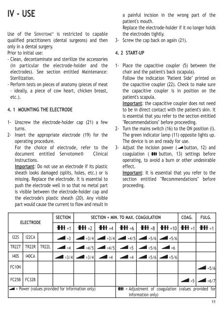
ELECTRODE<br />
a painful incision in the wrong part of the<br />
pati<strong>en</strong>t's mouth.<br />
Replace the electrode-holder if it no longer holds<br />
the electrodes tightly.<br />
3- Screw the cap back on again (21).<br />
4. 2 START-UP<br />
1- Place the capacitive coupler (5) betwe<strong>en</strong> the<br />
chair and the pati<strong>en</strong>t's back (scapula).<br />
Follow the indication "Pati<strong>en</strong>t Side" printed on<br />
the capacitive coupler (22). Check to make sure<br />
the capacitive coupler is in position on the<br />
pati<strong>en</strong>t's scapula.<br />
Important: the capacitive coupler does not need<br />
to be in direct contact with the pati<strong>en</strong>t's skin. It<br />
is ess<strong>en</strong>tial that you refer to the section <strong>en</strong>titled<br />
"Re<strong>com</strong>m<strong>en</strong>dations" before proceeding.<br />
2- Turn the mains switch (16) to the ON position (I).<br />
The gre<strong>en</strong> indicator lamp (11) opposite lights up.<br />
The device is on and ready for use.<br />
3- Adjust the incision power ( button, 12) and<br />
coagulation ( button, 13) settings before<br />
operating, to avoid a burn or other undesirable<br />
effect.<br />
Important: It is ess<strong>en</strong>tial that you refer to the<br />
section <strong>en</strong>titled "Re<strong>com</strong>m<strong>en</strong>dations" before<br />
proceeding.<br />
SECTION SECTION + MIN. TO MAX. COAGULATION COAG. FULG.<br />
=1 =2 =4 =6 =8 =10 =1 =1<br />
I22S I22CA =3 =3/4 =3/4 =4/5 =5/6 =5/6<br />
TR22T TR22R TR22L =4 =4/5 =4/5 =5 =5/6 =6<br />
I40S I40CA =3/4 =3/4 =4 =4 =5/6 =5/6<br />
FC10N =5/6<br />
FC25B FC32B =5 =6/7<br />
= Power (values provided for information only) = Adjustm<strong>en</strong>t of coagulation (values provided for<br />
information only)<br />
11