
You also want an ePaper? Increase the reach of your titles
YUMPU automatically turns print PDFs into web optimized ePapers that Google loves.
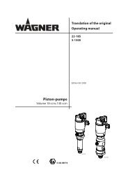
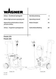
Betriebsanleitung<br />
Operating manual .................p. 24<br />
Mode d’emploi .......................p. 48<br />
Istruzioni per l’uso .................p. 71<br />
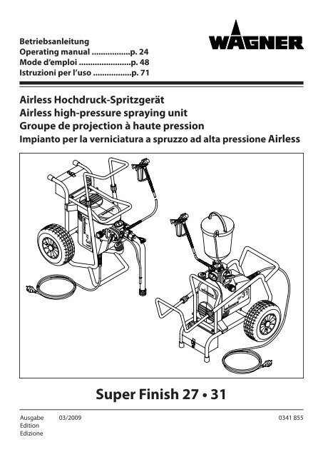
Airless Hochdruck-Spritzgerät<br />
Airless high-pressure spraying unit<br />
Groupe de projection à haute pression<br />
Impianto per la verniciatura a spruzzo ad alta pressione Airless<br />
Ausgabe 03/2009<br />
Edition<br />
Edizione<br />
3<br />
5 4<br />
<strong>Super</strong> <strong>Finish</strong> <strong>27</strong> <strong>•</strong> <strong>31</strong><br />
3<br />
5 4<br />
0341 855
D<br />
Warnung!<br />
Achtung, Verletzungsgefahr durch Injektion!<br />
Airless-Geräte entwickeln extrem hohe Spritzdrücke.<br />
1<br />
2<br />
3<br />
Niemals Finger, Hände oder andere Körperteile mit dem Spritzstrahl<br />
in Berührung bringen!<br />
Nie die Spritzpistole auf sich, Personen und Tiere richten.<br />
Nie die Spritzpistole ohne Spritzstrahl-Berührungsschutz benutzen.<br />
Behandeln Sie eine Spritzverletzung nicht als harmlose Schnittverletzung.<br />
Bei einer Hautverletzung durch Beschichtungsstoff oder<br />
Lösemittel sofort einen Arzt aufsuchen zur schnellen, fachkundigen<br />
Behandlung. Informieren Sie den Arzt über den verwendeten Beschichtungsstoff<br />
oder das Lösemittel.<br />
Vor jeder Inbetriebnahme sind gemäß Betriebsanleitung<br />
folgende Punkte zu beachten:<br />
1. Fehlerhafte Geräte dürfen nicht benutzt werden.<br />
2. <strong>Wagner</strong>-Spritzpistole sichern mit Sicherungshebel am<br />
Abzugsbügel<br />
3. Erdung sicherstellen – Der Anschluss muss über eine vorschriftsmäßig<br />
geerdete Schutzkontakt-Steckdose erfolgen.<br />
4. zulässigen Betriebsdruck vom Hochdruckschlauch und<br />
Spritzpistole überprüfen<br />
5. alle Verbindungsteile auf Dichtheit prüfen<br />
Anweisungen zur regelmäßigen Reinigung und Wartung des<br />
Gerätes sind streng einzuhalten.<br />
Vor allen Arbeiten am Gerät und bei jeder Arbeitspause folgende<br />
Regeln beachten:<br />
1. Spritzpistole und Hochdruckschlauch druckentlasten<br />
2. <strong>Wagner</strong>-Spritzpistole sichern mit Sicherungshebel am<br />
Abzugsbügel<br />
3. Gerät ausschalten.<br />
Achte auf Sicherheit!
Inhalt<br />
1. SIcherheItSvorSchrIFten Für<br />
daS aIrleSS-SprItzen ____________________ 2/3<br />
2. anwendungSüberSIcht _________________ 3/4<br />
2.1 Einsatzgebiete _______________________________ 3<br />
2.2 Beschichtungsstoffe ___________________________ 3<br />
3. gerätebeSchreIbung ____________________ 4-6<br />
3.1 Airless-Verfahren ______________________________ 4<br />
3.2 Funktion des Gerätes __________________________ 4<br />
3.3 Erklärungsbild ________________________________ 5<br />
– Vertikal-Aufstellung mit Ansaugsystem<br />
– Horizontal-Aufstellung mit Oberbehälter<br />
3.4 Technische Daten <strong>Super</strong> <strong>Finish</strong> <strong>27</strong> und <strong>31</strong> __________ 6<br />
3.5 Transport ____________________________________ 6<br />
4. InbetrIebnahme _________________________ 6-8<br />
4.1 Gerät mit Ansaugsystem ________________________ 6<br />
4.2 Gerät mit Oberbehälter (5 Liter) _______________ 6/7<br />
4.3 Hochdruckschlauch und Spritzpistole _____________ 7<br />
4.4 Anschluß an das Stromnetz _____________________ 7<br />
4.5 Bei Erstinbetriebnahme Reinigung von<br />
Konservierungsmittel __________________________ 7<br />
4.6 Gerät (Hydrauliksystem) entlüften, wenn das<br />
Geräusch des Einlassventils nicht hörbar ist _______ 7/8<br />
4.7 Gerät mit Beschichtungsstoff in Betrieb nehmen ____ 8<br />
4.8 Steckdose am Gerät ___________________________ 8<br />
5. SprItztechnIk _____________________________ 8<br />
6. handhabung deS hochdruckSchlaucheS _ 8<br />
6.1 Hochdruckschlauch____________________________ 8<br />
7. arbeItSunterbrechung ___________________ 9<br />
8. gerätereInIgung (auSSerbetrIebnahme) 9-11<br />
8.1 Gerätereinigung von außen ____________________ 10<br />
8.2 Ansaugfilter _________________________________ 10<br />
8.3 Hochdruckfilter (Zubehör) _____________________ 10<br />
8.4 Reinigung der Airless-Spritzpistole G 12 _______ 10/11<br />
9. hIlFe beI Störungen ___________________ 11–12<br />
10. wartung _________________________________ 13<br />
10.1 Allgemeine Wartung __________________________ 13<br />
10.2 Hochdruckschlauch___________________________ 13<br />
11. reparaturen am gerät _________________ 13-17<br />
11.1 Einlassventildrücker bei <strong>Super</strong> <strong>Finish</strong> <strong>31</strong> __________ 13<br />
11.2 Einlassventil ______________________________ 13/14<br />
11.3 Auslassventil ________________________________ 14<br />
11.4 Druckregelventil _____________________________ 14<br />
11.5 Entlastungsventil __________________________ 14/15<br />
<strong>Super</strong> <strong>Finish</strong> <strong>27</strong> <strong>•</strong> <strong>31</strong><br />
D<br />
Inhalt<br />
11.6 Membrane austauschen _______________________ 15<br />
11.7 Geräteanschlussleitung austauschen _____________ 16<br />
11.8 Schaltplan __________________________________ 17<br />
12. zubehör und erSatzteIle ______________ 18-21<br />
12.1 Zubehör für <strong>Super</strong> <strong>Finish</strong> <strong>27</strong> und <strong>31</strong> ______________ 18<br />
Zubehörbild für <strong>Super</strong> <strong>Finish</strong> <strong>27</strong> und <strong>31</strong> __________ 19<br />
Zubehörbild für <strong>Super</strong> <strong>Finish</strong> <strong>27</strong> und <strong>31</strong> __________ 95<br />
12.2 Ersatzteilliste Pumpenkopf <strong>Super</strong> <strong>Finish</strong> <strong>27</strong> und <strong>31</strong> __ 20<br />
Ersatzteilbild Pumpenkopf <strong>Super</strong> <strong>Finish</strong> <strong>27</strong> und <strong>31</strong> __ 96<br />
12.3 Ersatzteilliste Wagen __________________________ 20<br />
Ersatzteilbild Wagen __________________________ 97<br />
12.4 Ersatzteilliste Ansaugsystem ____________________ 20<br />
Ersatzteilbild Ansaugsystem ____________________ 97<br />
12.5 Ersatzteilliste Oberbehälter 5 Liter _______________ 20<br />
Ersatzteilbild Oberbehälter 5 Liter _______________ 97<br />
12.6 Ersatzteilliste Oberbehälter 20 Liter ______________ 20<br />
Ersatzteilbild Oberbehälter 20 Liter ______________ 97<br />
12.7 Ersatzteilliste Pumpen-Aggregat<br />
<strong>Super</strong> <strong>Finish</strong> <strong>27</strong> und <strong>31</strong> ________________________ 21<br />
Ersatzteilbild Pumpen-Aggregat<br />
<strong>Super</strong> <strong>Finish</strong> <strong>27</strong> und <strong>31</strong> ________________________ 98<br />
13. anhang ________________________________ 22-23<br />
13.1 Düsenauswahl ______________________________ 22<br />
13.2 Wartung und Reinigung von<br />
Airless-Hartmetall-Düsen ______________________ 22<br />
13.3 Spritzpistolen-Zubehör ________________________ 22<br />
13.4 Airless-Düsen Tabelle _________________________ 23<br />
prüFung deS geräteS __________________________ 99<br />
wIchtIger hInweIS zur produkthaFtung _____ 99<br />
entSorgungShInweIS _________________________ 99<br />
ce konFormItätSerklärung ___________________ 99<br />
garantIeerklärung ______________________ 99/100<br />
wagner ServIcenetz _________________________ 108<br />
1
Sicherheitsvorschriften<br />
1. SIcherheItSvorSchrIFten Für<br />
daS aIrleSS-SprItzen<br />
Die sicherheitstechnischen Anforderungen für Airless-<br />
Spritzgeräte sind geregelt in:<br />
a) europäische norm „Spritz- und Sprühgeräte für<br />
beschichtungsstoffe – Sicherheitsanforderungen“(en<br />
1953: 1998).<br />
b) die berufs-genossenschaftliche-vorschriften„arbeiten<br />
mit Flüssigkeitsstrahlern“ (bgv d15) und „verarbeiten<br />
von beschichtungsstoffen“(bgv d25).<br />
c) richtlinien zu bau- und ausführungsanforderungen für<br />
Flüssigkeitsstrahler (Spritzgeräte) der gewerblichen<br />
berufsgenossenschaften (zh1/406).<br />
Zum sicheren umgang mit airless hochdruck-Spritzgeräten<br />
sind folgende Sicherheitsvorschriften zu beachten.<br />
<strong>•</strong><br />
Flammpunkt<br />
nur beschichtungsstoffe mit einem Flammpunkt<br />
von 21°c oder darüber, ohne zusätzliche<br />
erwärmung, verspritzen. der Flammpunkt ist<br />
die niedrigste temperatur, bei der sich aus dem<br />
Gefahr Beschichtungsstoff Dämpfe entwickeln. Diese<br />
dämpfe reichen aus, um mit der über dem beschichtungsstoff<br />
stehenden luft ein entflammbares gemisch<br />
zu bilden.<br />
<strong>•</strong> explosionsschutz<br />
Gefahr<br />
gerät nicht benutzen in betriebsstätten, welche<br />
unter die explosionsschutz-verordnung<br />
fallen.<br />
<strong>•</strong> explosions- und brandgefahr bei Spritzarbeiten<br />
durch zündquellen<br />
es dürfen keine zündquellen in der umgebung<br />
vorhanden sein, wie z.b. offenes Feuer, rauchen<br />
von zigaretten, zigarren und tabakpfei-<br />
Gefahr fen, Funken, glühende drähte, heiße oberflächen<br />
usw.<br />
<strong>•</strong> verletzungsgefahr durch den Spritzstrahl<br />
Gefahr<br />
achtung verletzungsgefahr durch Injektion! nie die<br />
Spritzpistole auf sich, personen und tiere richten. nie die<br />
Spritzpistole ohne Spritzstrahl-Berührungsschutz benutzen.<br />
Spritzstrahl darf mit keinem körperteil in berührung<br />
kommen. Bei Airless-Spritzpistolen auftretende hohe<br />
Spritzdrücke können sehr gefährliche verletzungen verursachen.<br />
bei kontakt mit dem Spritzstrahl kann beschichtungsstoff<br />
in die Haut injiziert werden. Behandeln Sie eine Spritzverletzung<br />
nicht als harmlose Schnittverletzung. Bei einer<br />
hautverletzung durch beschichtungsstoff oder lösemit-<br />
D<br />
tel sofort einen arzt aufsuchen zur schnellen, fachkundigen<br />
Behandlung. Informieren Sie den Arzt über den<br />
verwendeten beschichtungsstoff oder das lösemittel.<br />
<strong>•</strong> Spritzpistole sichern gegen unbeabsichtigte<br />
Betätigung<br />
Spritzpistole bei Montage oder Demontage der Düse und<br />
bei Arbeitsunterbrechung immer sichern.<br />
rückstoß der Spritzpistole<br />
Bei hohem Betriebsdruck bewirkt Ziehen des Abzugsbügels<br />
eine Rückstoßkraft bis 15 N. Sollten<br />
Sie nicht darauf vorbereitet sein, kann die Hand<br />
Gefahr zurückgestoßen oder das Gleichgewicht verloren<br />
werden. Dies kann zu Verletzungen führen.<br />
2 <strong>Super</strong> <strong>Finish</strong> <strong>27</strong> <strong>•</strong> <strong>31</strong><br />
<strong>•</strong><br />
<strong>•</strong> atemschutz zum Schutz vor lösemitteldämpfen<br />
Bei Spritzarbeiten Atemschutz tragen.<br />
Dem Benutzer ist eine Atemschutzmaske zur Verfügung zu<br />
stellen (Berufs-Genossenschaftliche Regeln „Regeln für den<br />
Einsatz von Atemschutzgeräten“ (BGR 190), Berufs-Genossenschaftliche-Vorschriften<br />
„Arbeiten mit Flüssigkeitsstrahlern”<br />
(BGV D15) und „Verarbeiten von Beschichtungsstoffen“ (BGV<br />
D25).<br />
<strong>•</strong> vermeidung von berufskrankheiten<br />
Zum Schutz der Haut sind Schutzkleidung, Handschuhe und<br />
eventuell Hautschutzcreme erforderlich.<br />
Vorschriften der Hersteller beachten zu den Beschichtungsstoffen,<br />
Lösemittel und Reinigungsmittel bei Aufbereitung,<br />
Verarbeitung und Gerätereinigung.<br />
<strong>•</strong> max. betriebsdruck<br />
der zulässige betriebsdruck für die Spritzpistole, Spritzpistolen-zubehör<br />
und hochdruckschlauch darf nicht<br />
unter dem am gerät angegebenen maximalen betriebsdruck<br />
von 250 bar (25 mpa) liegen.<br />
<strong>•</strong> Hochdruckschlauch (Sicherheitshinweis)<br />
Elektrostatische Aufladung von Spritzpistole und Hochdruckschlauch<br />
wird über den Hochdruckschlauch abgeleitet.<br />
Deshalb muss der elektrische Widerstand zwischen den Anschlüssen<br />
des Hochdruckschlauchs gleich oder kleiner ein<br />
Megaohm betragen.<br />
i<br />
aus gründen der Funktion, Sicherheit und<br />
lebensdauer, nur wagner-original-hochdruckschläuche<br />
verwenden.<br />
<strong>•</strong> elektrostatische aufladung (Funken- oder<br />
Flammenbildung)<br />
Bedingt durch die Strömungsgeschwindigkeit des<br />
Beschichtungsstoffs beim Spritzen kann es unter<br />
Umständen am Gerät zu elektrostatischen Aufla-<br />
Gefahr dungen kommen. Diese können bei Entladung<br />
Funken- oder Flammenbildung nach sich ziehen.<br />
Deshalb ist es notwendig, dass das Gerät immer über die<br />
elektrische Installation geerdet ist. Der Anschluss muss über
eine vorschriftsmäßig geerdete Schutzkontakt-Steckdose erfolgen.<br />
<strong>•</strong> gerät im einsatz auf baustellen<br />
Anschluss an das Stromnetz nur über einen besonderen<br />
Speisepunkt z.B. über eine Fehlerstromschutzeinrichtung<br />
mit InF≤30 ma.<br />
<strong>•</strong> Belastung der Steckdose am Gerät<br />
Steckdose nicht mit mehr als 1000 watt belasten. eine angeschlossene<br />
kabeltrommel vollständig abrollen.<br />
<strong>•</strong> lüftung bei Spritzarbeiten in räumen<br />
Es ist eine ausreichende Lüftung zur Abführung der Lösemitteldämpfe<br />
zu gewährleisten.<br />
<strong>•</strong> Absaugeinrichtungen<br />
Diese sind entsprechend lokaler Vorschriften vom Gerätebenutzer<br />
zu erstellen.<br />
<strong>•</strong> erdung des Spritzobjekts<br />
Das zu beschichtende Spritzobjekt muss geerdet sein.<br />
<strong>•</strong><br />
<strong>•</strong><br />
gerätereinigung mit lösemittel<br />
Bei Gerätereinigung mit Lösemittel darf nicht in<br />
einen Behälter mit kleiner Öffnung (Spundloch)<br />
gespritzt oder gepumpt werden. Gefahr durch Bildung<br />
eines explosionsfähigen Gas-/Luftge-<br />
Gefahr<br />
misches. Der Behälter muss geerdet sein.<br />
Gerätereinigung<br />
kurzschlussgefahr durch eindringendes wasser!<br />
Gerät niemals mit Hochdruck- oder Dampf-<br />
Gefahr hochdruckreiniger abspritzen.<br />
Steckdose am gerät!<br />
eine feuchte reinigung im bereich der Steckdose und des<br />
Multifunktionsschalters nur bei ausgestecktem Gerätenetzstecker<br />
vornehmen.<br />
<strong>•</strong> arbeiten oder reparaturen an der elektrischen<br />
Ausrüstung<br />
Diese nur von einer Elektrofachkraft durchführen lassen. Für<br />
unsachgemäße Installation wird keine Haftung übernommen.<br />
<strong>•</strong> Arbeiten an elektrischen Bauteilen<br />
bei allen arbeiten den netzstecker aus der Steckdose ziehen.<br />
<strong>•</strong> Aufstellung in unebenem Gelände<br />
Die Vorderseite des Geräts muss nach unten zeigen, um Wegrutschen<br />
zu vermeiden. (Abb. 1)<br />
<strong>Super</strong> <strong>Finish</strong> <strong>27</strong> <strong>•</strong> <strong>31</strong><br />
D<br />
<br />
2. anwendungSüberSIcht<br />
2.1 eInSatzgebIete<br />
5 4<br />
3<br />
Sicherheitsvorschriften<br />
Alle Lackieraufträge in der Werkstatt und auf der Baustelle,<br />
kleine und großflächige Dispersionsarbeiten mit der Spritzpistole<br />
oder innengespeistem Airless-Roller, Korrosions- und<br />
Flammschutz.<br />
Spritzobjekt-Beispiele<br />
Türen, Türzargen, Geländer, Möbel, Holzverkleidungen, Zäune,<br />
Heizkörper und Stahlteile, Decken und Wände im Innenbereich,<br />
aber auch Fassaden, Tiefgaragen, Flamm- und Schallschutz<br />
für Stahlbau- und Holzkonstruktionen.<br />
2.2 beSchIchtungSStoFFe<br />
verarbeitbare beschichtungsstoffe<br />
i<br />
Achten Sie auf Airless-Qualität bei den zu verarbeitenden<br />
Beschichtungsstoffen.<br />
Wasserverdünnbare und lösemittelhaltige Lacke und Lackfarben,<br />
Zweikomponenten Beschichtungsstoffe, Dispersionen,<br />
Latexfarben, Fassadenfarben, Dach- und Bodenbeschichtungen,<br />
Flamm- und Korrosionsschutz-material.<br />
Die Verarbeitung anderer Beschichtungsstoffe nur mit Zustimmung<br />
der Firma WAGNER.<br />
Filterung<br />
Trotz Ansaugfilter, Einsteckfilter in der Spritzpistole und des<br />
als Zubehör erhältlichen Hochdruckfilters ist eine Filterung<br />
des Beschichtungsstoffes im allgemeinen zu empfehlen.<br />
3
Anwendungsübersicht /Gerätebeschreibung<br />
Beschichtungsstoff vor Arbeitsbeginn gut umrühren.<br />
i<br />
Achtung: Beim Aufrühren mit motorgetriebenen<br />
Rührwerken darauf achten, dass keine<br />
Luftblasen eingerührt werden. Luftblasen stören<br />
beim Spritzen, können sogar zur Betriebsunterbrechung<br />
führen.<br />
viskosität<br />
Mit dem Gerät ist es möglich, hochviskose Beschichtungsstoffe<br />
bis etwa 25.000 mPa·s zu verarbeiten.<br />
Lassen sich hochviskose Beschichtungsstoffe nicht ansaugen,<br />
so ist nach Herstellerangabe zu verdünnen.<br />
zweikomponenten-beschichtungsstoff<br />
Die entsprechende Verarbeitungszeit ist genau einzuhalten.<br />
Innerhalb dieser Zeit das Gerät sorgfältig mit dem entsprechenden<br />
Reinigungsmittel durchspülen und reinigen.<br />
beschichtungsstoffe mit scharfkantigen zusatzstoffen<br />
Diese üben auf Ventile, Hochdruckschlauch, Spritzpistole und<br />
Düse eine stark verschleißende Wirkung aus. Die Lebensdauer<br />
dieser Teile kann sich dadurch erheblich verkürzen.<br />
3. gerätebeSchreIbung<br />
3.1 aIrleSS verFahren<br />
Hauptanwendungsgebiete sind dicke Schichten von höherviskosem<br />
Beschichtungsstoff bei großen Flächen und hohem<br />
Materialeinsatz.<br />
Eine Membranpumpe saugt den Beschichtungsstoff an und<br />
fördert ihn unter Druck zur Düse. Bei einem Druck bis max.<br />
250 bar (25 MPa) durch die Düse gepresst, zerstäubt der<br />
Beschichtungsstoff. Dieser hohe Druck bewirkt eine mikrofeine<br />
Zerstäubung des Beschichtungsstoffes.<br />
Da in diesem System keine Luft verwendet wird, bezeichnet<br />
man dieses Verfahren als AIRLESS Verfahren (luftlos).<br />
Diese Art zu spritzen bringt die Vorteile von feinster Zerstäubung,<br />
nebelarmer Betriebsweise und glatter, blasenfreier<br />
Oberfläche. Neben diesen Vorteilen sind die Arbeitsgeschwindigkeit<br />
und die große Handlichkeit zu nennen.<br />
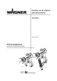
3.2 FunktIon deS geräteS<br />
Zum besseren Verständnis der Funktion kurz den technischen<br />
Aufbau.<br />
WAGNER <strong>Super</strong> <strong>Finish</strong> <strong>27</strong> und <strong>31</strong> sind elektrisch angetriebene<br />
Hochdruck-Spritzgeräte.<br />
Der Elektromotor (Abb. 2, Pos. 1) treibt über den Zahnriemen (2)<br />
die Pumpe an.<br />
In der Pumpe bewegt sich die Membrane (3) durch Hydrauliköl<br />
auf und ab. Durch die Abwärtsbewegung der<br />
Membrane öffnet das Einlassventil selbständig. Durch die<br />
D<br />
Aufwärtsbewegung der Membrane öffnet das Auslassventil.<br />
Der Beschichtungsstoff strömt unter hohem Druck<br />
durch den Hochdruckschlauch zur Spritzpistole. Bei Austritt<br />
aus der Düse zerstäubt der Beschichtungsstoff.<br />
Das Druckregelventil (4) regelt die Fördermenge und den Betriebsdruck<br />
des Beschichtungsstoffs.<br />
4 <strong>Super</strong> <strong>Finish</strong> <strong>27</strong> <strong>•</strong> <strong>31</strong><br />
<br />
3<br />
2<br />
5 4<br />
3<br />
1<br />
4
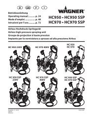
3.3 erklärungSbIld<br />
vertikal-aufstellung mit ansaugsystem<br />
<br />
19<br />
18<br />
17<br />
16<br />
15<br />
20<br />
14<br />
13<br />
<strong>Super</strong> <strong>Finish</strong> <strong>27</strong> <strong>•</strong> <strong>31</strong><br />
3<br />
5 4<br />
12<br />
Horizontal-Aufstellung mit Oberbehälter<br />
<br />
5 4<br />
3<br />
11<br />
3<br />
21<br />
22<br />
D<br />
1<br />
2<br />
4<br />
5<br />
6<br />
8<br />
9<br />
10<br />
7<br />
Gerätebeschreibung<br />
1 Spritzpistole<br />
2 Hochdruckschlauch<br />
3 Auslassventil<br />
4 Steckdose max. Belastung 1000 Watt<br />
5 Einlassventil Beschichtungssto-Eingang<br />
6 Einlassventildrücker*<br />
7 Anschluss zur Reinigung mit der Spritzpis-<br />
tole<br />
8 Ansaugrohr<br />
9 Rücklaufrohr<br />
10 Filter, Maschenweite 1 mm<br />
11 Ölmessstab unter der Ölverschluss-<br />
schraube<br />
12 Staubschutzkappe<br />
13 Multifunktionsschalter Symbole:<br />
(AUS)<br />
(EIN - Zirkulation)<br />
(Spritzen)<br />
14 Kontrollleuchte zeigt Betriebsbereit-<br />
schaft an<br />
15 Druckregelventil<br />
16 Manometer<br />
17 Deichselarretierung<br />
18 Deichsel ausziehbar<br />
19 Werkzeugbox*<br />
20 Einhängeöse für die Spritzpistole<br />
* Bei <strong>Super</strong> <strong>Finish</strong> <strong>31</strong><br />
21 Oberbehälter, Inhalt 5 Liter<br />
22 Rücklaufrohr<br />
(nicht positionierte Teile wie<br />
Abbildung 3)<br />
5
Gerätebeschreibung/ Inbetriebnahme<br />
3.4 technISche daten<br />
<strong>Super</strong> <strong>Finish</strong><br />
<strong>27</strong><br />
<strong>Super</strong> <strong>Finish</strong><br />
<strong>31</strong><br />
Spannung: 230 Volt~,50 Hz<br />
Absicherung<br />
Spannung am Multifunkti-<br />
16 A träge<br />
onsschalter: 24 V<br />
Geräteanschlussleitung: 6 m lang,3 x 1,5 mm<br />
Steckdose am Gerät: 230 Volt ~,50 Hz<br />
max. Anschluss: 1000 Watt<br />
Schutzart: IP 44 IP 54<br />
Aufnahmeleistung: 1,5 kW 1,7 kW<br />
max. Betriebsdruck: 250 bar (25 MPa)<br />
max. Volumenstrom: 3,0 l/min 3,5 l/min<br />
Volumenstrom bei 120 bar<br />
(12 MPa) mit Wasser:<br />
2,5 l/min 3,2 l/min<br />
max. Düsengröße 0,0<strong>27</strong> inch 0,0<strong>31</strong> inch<br />
(Zoll)<br />
(Zoll)<br />
max. Temperatur des Be-<br />
– 0,69 mm – 0,79 mm<br />
schichtungsstoffs: 43°C<br />
max. Viskosität: 25.000 mPa·s<br />
Leergewicht: 40 kg 43 kg<br />
Hydrauliköl-Füllmenge 0,9 Liter, ESSO NUTO H 22<br />
max. Reifendruck: 2 bar (0,2 MPa)<br />
max. Schalldruckpegel: 74 dB (A)*<br />
*Messort: Abstand 1 m seitlich vom Gerät und 1,60 m über dem<br />
Boden, 120 bar (12 MPa) Betriebsdruck, schallharter Boden<br />
3.5 tranSport<br />
Gerät schieben oder ziehen. Klemmhülsen (Abb. 5, Pos. 1) an<br />
der Deichsel lösen ( auf). Deichsel auf Länge nach Wunsch<br />
herausziehen. Klemmhülsen wieder von Hand anziehen (<br />
zu).<br />
<br />
1<br />
5 4<br />
3<br />
D<br />
transport im Fahrzeug<br />
Hochdruckschlauch aufrollen und über die Deichsel legen.<br />
Gerät mit geeignetem Befestigungsmittel sichern.<br />
4. InbetrIebnahme<br />
4.1 gerät mIt anSaugSyStem<br />
1. Staubschutzkappe (Abb. 6, Pos. 1) abschrauben.<br />
2. Auf saubere Dichtflächen an den Anschlüssen achten. Darauf<br />
achten, dass der rote Einlauf (2) in den Beschichtungsstoff-<br />
Eingang eingesetzt ist.<br />
3. Überwurfmutter (3) am Ansaugrohr (4) auf den Beschichtungsstoff-Eingang<br />
(5) mit beiliegendem Schlüssel 41 mm<br />
schrauben und anziehen.<br />
4. Überwurfmutter (6) am Rücklaufrohr (7) auf den Anschluss<br />
(8) schrauben.<br />
6 <strong>Super</strong> <strong>Finish</strong> <strong>27</strong> <strong>•</strong> <strong>31</strong><br />
<br />
3<br />
5 4<br />
1 8<br />
4.2 gerät mIt oberbehälter (5 lIter)<br />
1. Staubschutzkappe (Abb. 7, Pos. 1) abschrauben.<br />
2. Auf saubere Dichtflächen an den Anschlüssen achten. Darauf<br />
achten, dass der rote Einlauf (2) in den Beschichtungsstoff-<br />
Eingang eingesetzt ist.<br />
3. Oberbehälter (3) auf den Beschichtungsstoff-Eingang (4)<br />
schrauben.<br />
4. Rücklaufrohr (5) in den Oberbehälter einhängen.<br />
5. Überwurfmutter (6) am Rücklaufrohr (5) auf den Anschluss<br />
(7) schrauben.<br />
7<br />
6<br />
5<br />
2<br />
3<br />
4
5<br />
6<br />
7<br />
1<br />
4.3 hochdruckSchlauch und SprItzpIStole<br />
1.<br />
2.<br />
3.<br />
<br />
Hochdruckschlauch (Abb. 8, Pos. 1) am Schlauchanschluss<br />
(2) anschrauben.<br />
Spritzpistole (3) mit ausgewählter Düse am Hochdruckschlauch<br />
anschrauben.<br />
Überwurfmuttern am Hochdruckschlauch fest anziehen,<br />
damit kein Beschichtungsstoff austritt.<br />
1<br />
2<br />
3<br />
<strong>Super</strong> <strong>Finish</strong> <strong>27</strong> <strong>•</strong> <strong>31</strong><br />
5 4<br />
3<br />
5 4<br />
3<br />
3<br />
2<br />
4<br />
D<br />
4.4 anSchluSS an daS Stromnetz<br />
Achtung<br />
Inbetriebnahme<br />
Der Anschluss muss über eine vorschriftsmäßig<br />
geerdete Schutzkontakt-Steckdose erfolgen.<br />
Vor Anschluss an das Stromnetz darauf achten, dass die<br />
Netzspannung übereinstimmt mit der Angabe auf dem<br />
Leistungsschild an der Rückseite des Gerätes.<br />
Sobald der Netzstecker angeschlossen ist, leuchtet die grüne<br />
Kontrollleuchte.<br />
4.5 beI erStInbetrIebnahme reInIgung von<br />
konServIerungSmIttel<br />
1. Gerät mit Ansaugsystem<br />
Ansaugrohr in einen mit geeignetem Reinigungsmittel<br />
gefüllten Behälter eintauchen.<br />
2. Gerät mit Oberbehälter<br />
Geeignetes Reinigungsmittel in den Oberbehälter<br />
einfüllen.<br />
3. Multifunktionsschalter (Abb. 9, Pos. 1) auf (EIN<br />
-Zirkulation) stellen, das Gerät läuft an. Druckregulierknopf<br />
(2) bis zum Anschlag nach rechts drehen.<br />
4. Abwarten bis am Rücklaufrohr Reinigungsmittel austritt.<br />
5. Multifunktionsschalter (1) auf (Spritzen) stellen.<br />
Abzugsbügel der Spritzpistole ziehen.<br />
6. Reinigungsmittel aus dem Gerät in einen offenen Sammelbehälter<br />
spritzen.<br />
<br />
1<br />
4.6 gerät (hydraulIkSyStem) entlüFten, wenn<br />
daS geräuSch deS eInlaSSventIlS nIcht<br />
hörbar ISt.<br />
1. Druckregulierknopf (Abb. 10, Pos. 1) drei umdrehungen<br />
nach links drehen.<br />
2. Multifunktionsschalter (2) auf (EIN - Zirkulation) stellen.<br />
3.<br />
4.<br />
Das Hydrauliksystem entlüftet sich. Gerät zwei bis drei<br />
Minuten eingeschaltet lassen.<br />
Dann den Druckregulierknopf (1) bis zum Anschlag nach<br />
rechts drehen. Geräusch des Einlassventils ist hörbar.<br />
Wenn nicht, Punkt 1 und 3 wiederholen.<br />
5 4<br />
3<br />
2<br />
7
Inbetriebnahme/ Spritztechnik<br />
<br />
2<br />
4.7 gerät mIt beSchIchtungSStoFF In betrIeb<br />
nehmen<br />
1. <strong>Super</strong> <strong>Finish</strong> <strong>27</strong><br />
Vor Montage von Ansaugsystem oder Oberbehälter,<br />
Einlassventil auf Funktion prüfen. Mit einem<br />
weichen Dorn (z.B. Bleistift) auf das Einlassventil<br />
Achtung<br />
drücken, es muss sich be-wegen lassen.<br />
2. Gerät mit Ansaugsystem<br />
Ansaugrohr in einen mit Beschichtungsstoff gefüllten Behälter<br />
eintauchen.<br />
3. Gerät mit Oberbehälter<br />
Beschichtungsstoff in den Oberbehälter einfüllen.<br />
4. <strong>Super</strong> <strong>Finish</strong> <strong>31</strong><br />
Einlassventildrücker (Abb. 11, Pos. 1) mehrmals drücken, um<br />
ein eventuell verklebtes Einlassventil zu lösen.<br />
5. Multifunktionsschalter (2) auf (EIN – Zirkulation) stellen,<br />
6.<br />
das Gerät läuft an. Druckregulierknopf (3) bis zum Anschlag<br />
nach rechts drehen.<br />
Wenn das Geräusch der Ventile deutlich zu hören ist, so ist<br />
das Gerät entlüftet.<br />
7. Multifunktionsschalter (2) auf (Spritzen) stellen.<br />
8.<br />
<br />
Abzugsbügel der Spritzpistole ziehen, dann den gewünschten<br />
Betriebsdruck mit dem Druckregulierknopf (3) einstellen.<br />
Das Gerät ist spritzbereit.<br />
1<br />
2<br />
3<br />
5 4<br />
3<br />
5 4<br />
3<br />
1<br />
D<br />
4.8 SteckdoSe am gerät<br />
Es kann z.B. ein Rührwerk, eine Arbeitsleuchte usw. mit<br />
max. 1000 watt angeschlossen werden.<br />
Achtung<br />
Achtung<br />
Eine angeschlossene Kabeltrommel vollständig<br />
abrollen.<br />
Damit beim Einschalten des Gerätes die Netzabsicherung<br />
mit 16 A nicht anspricht: Immer<br />
zuerst das Gerät <strong>Super</strong> <strong>Finish</strong> <strong>27</strong> oder <strong>31</strong> einschalten,<br />
dann das angeschlossene Gerät.<br />
5. SprItztechnIk<br />
Während des Spritzvorganges die Spritzpistole gleichmäßig<br />
führen. Bei Nichteinhaltung tritt ein unregelmäßiges Spritzbild<br />
auf. Die Spritzbewegung mit dem Arm ausführen und<br />
nicht mit dem Handgelenk. Einen parallelen Abstand von ca.<br />
30 cm zwischen Spritzpistole und Spritzobjekt einhalten. Die<br />
seitliche Abgrenzung des Spritzstrahles soll nicht zu scharf<br />
sein. Der Spritzrand sollte allmählich auflockern, damit beim<br />
nächsten Durchgang leicht überlappt werden kann. Spritzpistole<br />
immer parallel und im Winkel von 90° zur Spritzfläche<br />
führen, so entsteht am wenigsten Farbnebel.<br />
8 <strong>Super</strong> <strong>Finish</strong> <strong>27</strong> <strong>•</strong> <strong>31</strong><br />
i<br />
Beim Auftreten sehr scharfer Randzonen und<br />
Streifen im Spritzstrahl – Betriebsdruck erhöhen<br />
oder Beschichtungsstoff verdünnen.<br />
6. handhabung deS hochdruck-<br />
SchlaucheS<br />
Scharfes Biegen oder Knicken des Hochdruckschlauches vermeiden,<br />
kleinster Biegeradius etwa 10 cm.<br />
Hochdruckschlauch nicht überfahren, sowie vor scharfen Gegenständen<br />
und Kanten schützen.<br />
Achtung<br />
Verletzungsgefahr durch undichten Hochdruckschlauch.<br />
Beschädigten Hochdruckschlauch<br />
sofort ersetzen.<br />
Niemals defekten Hochdruckschlauch selbst<br />
reparieren!<br />
6.1 hochdruckSchlauch<br />
Das Gerät ist mit einem speziell für Membranpumpen geeigneten<br />
Hochdruckschlauch ausgerüstet.<br />
i<br />
Aus Gründen der Funktion, Sicherheit und Lebensdauer<br />
nur WAGNER Original-Hochdruckschläuche<br />
verwenden.
7. arbeItSunterbrechung<br />
1. Gerät ausschalten, Multifunktionsschalter auf (Druckentlastung,<br />
Zirkulation), dann auf (AUS) stellen.<br />
2. Spritzpistole sichern, siehe Betriebsanleitung der Spritzpistole.<br />
3.<br />
Falls die Düse gereinigt werden soll, siehe Seite 22, Punkt<br />
13.2.<br />
4. Gerät mit Ansaugsystem<br />
Ansaugsystem im Beschichtungsstoff eingetaucht lassen oder<br />
dieses in das entsprechende Reinigungsmittel eintauchen.<br />
Ansaugfilter und Gerät sollen nicht austrocknen.<br />
Achtung<br />
<strong>Super</strong> <strong>Finish</strong> <strong>27</strong> <strong>•</strong> <strong>31</strong><br />
Beim Einsatz von schnelltrocknenden– oder<br />
Zweikomponenten-Beschichtungsstoff, Gerät<br />
unbedingt innerhalb der Verarbeitungszeit mit<br />
geeignetem Reinigungsmittel durchspülen.<br />
8. gerätereInIgung<br />
(auSSerbetrIebnahme)<br />
Sauberkeit ist die sicherste Gewährleistung für einen störungsfreien<br />
Betrieb. Nach Beendigung der Spritzarbeiten Gerät<br />
reinigen. Auf keinen Fall dürfen Beschichtungsstoffreste im<br />
Gerät antrocknen und sich festsetzen. Das zur Reinigung verwendete<br />
Reinigungsmittel (nur mit einem Flammpunkt über<br />
21°C) muss dem Beschichtungsstoff entsprechen.<br />
<strong>•</strong> Spritzpistole sichern, siehe Betriebsanleitung der<br />
Spritzpistole. Düse demontieren und reinigen, siehe Seite 22,<br />
Punkt 13.2.<br />
<strong>•</strong> gerät mit ansaugsystem (abb. 12)<br />
1. Ansaugsystem aus dem Materialbehälter nehmen ,z.B. Gerät<br />
in Horizontal-Aufstellung bringen.<br />
2. Gerät einschalten, Multifunktionsschalter auf (EIN –<br />
Zirkulation) und weiter auf (Spritzen) stellen.<br />
3.<br />
Abzugsbügel an der Spritzpistole ziehen, um restlichen<br />
Beschichtungsstoff aus dem Ansaugrohr, Hochdruckschlauch<br />
und der Spritzpistole in einen offenen Behälter pumpen.<br />
Achtung<br />
Gefahr<br />
Bei lösemittelhaltigen Beschichtungsstoffen<br />
muss der Behälter geerdet werden.<br />
vorsicht! nicht in behälter mit kleiner öffnung<br />
(Spundloch) pumpen oder spritzen!<br />
Siehe Sicherheitsvorschriften.<br />
4. Ansaugsystem in ein geeignetes Reinigungsmittel<br />
eintauchen.<br />
5. Multifunktionsschalter auf (AUS) stellen.<br />
6. Spritzpistole am Ansaugrohr (Abb. 12) mit beiden<br />
beiliegenden Schlüsseln 22 mm anschrauben.<br />
7. Multifunktionsschalter auf (EIN – Zirkulation) stellen.<br />
8.<br />
Geeignetes Reinigungsmittel etwa eine Minute im Kreislauf<br />
D<br />
Arbeitsunterbrechung/ Gerätereinigung<br />
pumpen.<br />
9. Abzugsbügel an der Spritzpistole ziehen und mit Klammer<br />
arretieren.<br />
10. Multifunktionsschalter auf (Spritzen) stellen.<br />
11. Ansaugrohr etwa drei Minuten reinigen.<br />
12. Im Kreislauf spülen – Multifunktionsschalter auf (EIN)<br />
stellen.<br />
13. Spritzpistole schließen.<br />
14. Bei Reinigung mit Wasser, den Vorgang etwa drei Minuten<br />
mit klarem Wasser wiederholen.<br />
15. Gerät ausschalten – Multifunktionsschalter auf (AUS)<br />
stellen.<br />
Achtung<br />
Achtung<br />
die reinigungswirkung erhöht sich, wenn<br />
der Abzugsbügel der Spritzpistole im<br />
wechsel betätigt und wieder losgelassen<br />
wird.<br />
Bei wasserverdünnbaren Beschichtungsstoffen<br />
verbessert warmes wasser die reinigung.<br />
<br />
<strong>•</strong> Gerät mit Oberbehälter<br />
1. Oberbehälter mit geeignetem Reinigungsmittel füllen.<br />
2. Gerät einschalten, Multifunktionsschalter auf (EIN –<br />
Zirkulation) stellen.<br />
3. Gerät bei geschlossener Spritzpistole (ohne Düse) einige<br />
Minuten im Kreislauf betreiben.<br />
4. Multifunktionsschalter auf (Spritzen) stellen.<br />
5. Abzugsbügel an der Spritzpistole ziehen.<br />
6. Reinigungsmittel in einen separaten, offenen Behälter<br />
pumpen, bis das Gerät leer ist.<br />
Achtung<br />
Bei lösemittelhaltigen Beschichtungsstoffen<br />
muss der Behälter geerdet werden.<br />
9
Gerätereinigung<br />
Gefahr<br />
vorsicht! nicht in behälter mit kleiner öffnung<br />
(Spundloch) pumpen oder spritzen!<br />
Siehe Sicherheitsvorschriften.<br />
7. Gerät ausschalten, Multifunktionsschalter auf (AUS)<br />
stellen.<br />
8.1 gerätereInIgung von auSSen<br />
Gefahr<br />
Gefahr<br />
zuerst netzstecker aus der Steckdose ziehen.<br />
kurzschlussgefahr durch eindringendes<br />
wasser! gerät niemals mit hochdruck- oder<br />
Dampfhochdruckreiniger abspritzen.<br />
Gerät außen mit einem in geeignetem Reinigungsmittel getränkten<br />
Tuch abwischen. Auch im Bereich der Steckdose und<br />
des Multifunktionsschalters sorgfältig reinigen.<br />
8.2 anSaugFIlter<br />
i<br />
Saubere Filter gewährleisten stets maximale<br />
Fördermenge, konstanten Spritzdruck und einwandfreies<br />
Funktionieren des Gerätes.<br />
<strong>•</strong> Gerät mit Ansaugsystem<br />
1. Filter (Abb. 13) vom Ansaugrohr abschrauben.<br />
2. Filter reinigen oder austauschen. Reinigung mit einem<br />
harten Pinsel und entsprechendem Reinigungsmittel<br />
durchführen.<br />
<br />
<strong>•</strong> Gerät mit Oberbehälter<br />
1. Mit Schraubendreher Schrauben lösen (Abb. 14, Pos. 1).<br />
2. Filterscheibe mit einem Schraubendreher anheben (2) und<br />
herausnehmen.<br />
3.<br />
Filterscheibe reinigen oder austauschen Reinigung mit<br />
einem harten Pinsel und entsprechendem Reinigungsmittel<br />
durchführen.<br />
D<br />
10 <strong>Super</strong> <strong>Finish</strong> <strong>27</strong> <strong>•</strong> <strong>31</strong><br />
<br />
8.3 hochdruckFIlter (zubehör)<br />
<strong>•</strong> Gerät ausschalten – Multifunktionsschalter auf (AUS)<br />
stellen.<br />
<strong>•</strong> Hochdruckfilter öffnen und Filtereinlage reinigen, dazu:<br />
1. Gabelschlüssel in den Schlitz des Filtergehäuses (Abb. 15,<br />
Pos. 1) einlegen – Filtergehäuse herausschrauben.<br />
2. Filtergehäuse (1), Stützkörper (2), Zentrierring (4) und O-Ring<br />
(5) abnehmen.<br />
3. Filtereinlage (3) einrollen (bei Filtereinlage mit 70<br />
Maschen nicht notwendig) und aus dem Stützkörper (2)<br />
herausziehen.<br />
4. Alle Teile mit entsprechendem Reinigungsmittel reinigen.<br />
Falls Druckluft vorhanden – Filtereinlage und Stützkörper<br />
durchblasen.<br />
5. Hochdruckfilter wieder montieren.<br />
<br />
8.4 reInIgung der aIrleSS-SprItzpIStole g 12<br />
<strong>•</strong> Airless-Spritzpistole bei niedrigem Betriebsdruck mit<br />
geeignetem Reinigungsmittel durchspülen.<br />
<strong>•</strong> Düse gründlich mit geeignetem Reinigungsmittel reinigen, so<br />
dass keine Beschichtungsstoffreste zurückbleiben.<br />
<strong>•</strong> Airless-Spritzpistole außen gründlich reinigen.<br />
1<br />
2<br />
3<br />
4<br />
5<br />
2<br />
1
einsteckfilter in der airless-Spritzpistole<br />
demontage (abb. 16)<br />
1. Schutzbügel (1) kräftig nach vorne ziehen.<br />
2. Griff (2) aus dem Pistolengehäuse schrauben. Einsteckfilter<br />
(3) herausziehen.<br />
3. Einsteckfilter verstopft oder defekt – ersetzen.<br />
Montage<br />
1.<br />
2.<br />
Einsteckfilter (3) mit dem längeren Konus in das Pistolengehäuse<br />
stecken.<br />
Griff (2) in das Pistolengehäuse einschrauben und anziehen.<br />
9. hIlFe beI Störungen<br />
<strong>Super</strong> <strong>Finish</strong> <strong>27</strong> <strong>•</strong> <strong>31</strong><br />
D<br />
3.<br />
<br />
1<br />
Schutzbügel (1) einrasten.<br />
Made in Germany<br />
G12<br />
max.<br />
3900 psi<br />
<strong>27</strong>0 bar<br />
Gerätereinigung/ Hilfe bei Störungen<br />
art der Störung mögliche ursache maßnahme zur behebung der<br />
Störung<br />
Gerät läuft nicht an <strong>•</strong> Keine Spannung vorhanden<br />
<strong>•</strong> Sicherung hat angesprochen.<br />
Zum Beispiel ist ein Rührwerk an der<br />
Steckdose am Gerät angeschlossen.<br />
Dieses Rührwerk wurde nicht<br />
ausgeschaltet, vor Einschalten des<br />
Gerätes <strong>Super</strong> <strong>Finish</strong> <strong>27</strong> oder <strong>31</strong>.<br />
<strong>•</strong> Gerät automatisch ab. Die grüne<br />
Kontrollleuchte im Multifunktionsschalter<br />
erlischt.<br />
Bei Überlastung schaltet sich das<br />
Das Gerät schaltet nicht selbständig<br />
wieder ein.<br />
Gerät saugt nicht an Gerät mit Ansaugsystem:<br />
Filter ragt über den Flüssigkeitsspiegel<br />
<strong>•</strong> hinaus und saugt Luft an.<br />
<strong>•</strong> Ansaugfilter verstopft<br />
<strong>•</strong> Ansaugrohr nicht fest angezogen, d. h.<br />
das Gerät saugt Nebenluft.<br />
Gerät mit Oberbehälter:<br />
<strong>•</strong> Filterscheibe verstopft<br />
<strong>Super</strong> <strong>Finish</strong> <strong>31</strong>:<br />
<strong>•</strong> Einlassventildrücker undicht, saugt<br />
Nebenluft.<br />
<strong>Super</strong> <strong>Finish</strong> <strong>27</strong>:<br />
<strong>•</strong> Einlassventil verklebt, lässt sich nicht im<br />
Einlassventilgehäuse niederdrücken.<br />
<strong>Super</strong> <strong>Finish</strong> <strong>31</strong>:<br />
Einlassventil verklebt<br />
<strong>•</strong><br />
<strong>•</strong> Spannungsversorgung prüfen<br />
<strong>•</strong> Zuerst das Gerät <strong>Super</strong> <strong>Finish</strong> <strong>27</strong> oder <strong>31</strong>,<br />
dann das z. B. angeschlossene Rührwerk<br />
einschalten.<br />
<strong>•</strong> Nach 2 – 3 Minuten leuchtet die grüne<br />
Kontrollleuchte wieder auf. Dann Multifunktionsschalter<br />
auf (AUS) stellen.<br />
Gerät wieder einschalten (EIN – Zirkulation),<br />
danach Multifunktionsschalter auf<br />
(Spritzen) stellen.<br />
<strong>•</strong> Beschichtungsstoff nachfüllen<br />
<strong>•</strong> Ansaugfilter reinigen oder austauschen<br />
<strong>•</strong> Anschlussstellen reinigen und anziehen.<br />
<strong>•</strong> Filterscheibe reinigen oder austauschen<br />
<strong>•</strong> Abstreifer und O-Ring auswechseln, siehe<br />
Seite 13, Punkt 11.1.<br />
Gerät ausschalten – (AUS)<br />
<strong>•</strong> Einlassventil muss beweglich sein, dazu mit<br />
einem weichen Dorn (z.B. Bleistift) leicht<br />
auf das Einlassventil drücken. Hin- und<br />
Herbewegen des Einlassventils beseitigt<br />
Verunreinigungen auf dem Ventilsitz. Hilft<br />
dies nicht, Einlassventil aus der Farbstufe<br />
herausschrauben und reinigen, siehe Seite<br />
13, Punkt 11.2.<br />
Gerät ausschalten – (AUS)<br />
<strong>•</strong> Den Einlassventildrücker (Abb. 17, Pos. 1)<br />
mehrmals drücken, dadurch löst sich das<br />
verklebte Einlassventil.<br />
3<br />
2<br />
11
Hilfe bei Störungen<br />
art der Störung mögliche ursache maßnahme zur behebung der<br />
Störung<br />
Gerät saugt nicht an<br />
gerät saugt an, aber es kommt zu<br />
keinem Druckaufbau<br />
Gerät saugt an und kommt auf<br />
druck. wird die Spritzpistole<br />
abgezogen, sinkt der druck stark<br />
ab.<br />
Harte Druckschläge und übermäßige<br />
vibrationen an Spritzpistole<br />
und Gerät<br />
D<br />
<strong>•</strong> Ansaugfilter verstopft<br />
Speziell für Gerät mit Ansaugsystem:<br />
<strong>•</strong> Ansaugrohr nicht fest angezogen<br />
<strong>•</strong> Auslassventilteile verschlissen<br />
12 <strong>Super</strong> <strong>Finish</strong> <strong>27</strong> <strong>•</strong> <strong>31</strong><br />
<br />
1<br />
Achtung<br />
einlassventildrücker<br />
(abb.17, pos. 1) nur von<br />
Hand drücken – niemals mit<br />
einem hammer auf den einlassventildrücker<br />
schlagen.<br />
<strong>•</strong> Einlassventil schließt nicht, da z.B. die <strong>•</strong> Einlassventil aus der Farbstufe herausschrau-<br />
Führung verklebt ist.<br />
ben und reinigen, siehe Seite 13, Punkt<br />
11.2.<br />
<strong>•</strong> Auslassventil verklebt<br />
<strong>•</strong> Auslassventil aus der Farbstufe herausschrauben<br />
und reinigen, siehe Seite 14,<br />
Punkt 11.3.<br />
<strong>•</strong> Luft im Hydrauliksystem<br />
<strong>•</strong> Gerät (Hydrauliksystem) entlüften, d.h.<br />
Druckregelventil drei Umdrehungen nach<br />
links drehen. Gerät etwa ein – zwei Minuten<br />
laufen lassen. Danach Druckregelventil<br />
nach rechts drehen, um den gewünschten<br />
Betriebsdruck einzustellen.<br />
<strong>•</strong> Keine Düse in der Spritzpistole <strong>•</strong> Düse montieren<br />
<strong>•</strong> Düse zu groß<br />
<strong>•</strong> Wahl einer kleineren Düse, siehe Seite 23,<br />
Punkt 13.4.<br />
<strong>•</strong> Ansaugfilter reinigen oder austauschen.<br />
<strong>•</strong> Entlastungsventil schließt nicht.<br />
Beschichtungsstoff tritt bei<br />
Schalterstellung (Spritzen) aus<br />
dem Rücklaufrohr aus.<br />
<strong>•</strong> Hochdruckschlauch für Membrangerät<br />
nicht geeignet<br />
<strong>•</strong> Auslassventilteile verschlissen<br />
<strong>•</strong> Anschlussstellen reinigen und anziehen.<br />
<strong>•</strong> Auslassventilteile austauschen, siehe Seite<br />
14, Punkt 11.3.<br />
<strong>•</strong> Entlastungsventil aus der Farbstufe herausschrauben<br />
und reinigen oder austauschen,<br />
siehe Seite 14, Punkt 11.5.<br />
<strong>•</strong> Original <strong>Wagner</strong> Hochdruckschlauch verwenden.<br />
<strong>•</strong> Auslassventilteile austauschen, siehe<br />
Seite14, Punkt 11.3.
10. wartung<br />
10.1 allgemeIne wartung<br />
Die Wartung des Gerätes soll einmal jährlich durch den <strong>Wagner</strong>-Service<br />
durchgeführt werden.<br />
1. Hochdruckschläuche, Geräteanschlussleitung, Stecker und<br />
Steckdose am Gerät auf Beschädigung prüfen.<br />
2. Einlass-, Auslassventil, Membrane und Filter auf Verschleiss<br />
prüfen.<br />
3. Ölstand (Abb. 18) in Horizontal-Aufstellung prüfen.<br />
<br />
10.2 hochdruckSchlauch<br />
<strong>Super</strong> <strong>Finish</strong> <strong>27</strong> <strong>•</strong> <strong>31</strong><br />
max.<br />
min.<br />
Hochdruckschlauch optisch auf eventuell vorhandene Einschnitte<br />
oder Ausbeulungen, insbesondere am Übergang in<br />
die Armatur, prüfen. Überwurfmuttern müssen sich frei drehen<br />
lassen.<br />
11. reparaturen am gerät<br />
Gefahr<br />
Gerät ausschalten (auS).<br />
vor allen reparaturen – netzstecker aus der<br />
Steckdose ziehen.<br />
11.1 eInlaSSventIldrücker (abb. 19) beI <strong>Super</strong><br />
FInISh <strong>31</strong><br />
1. Einlassventildrücker<br />
herausschrauben.<br />
mit Schlüssel 17 mm<br />
2.<br />
Abstreifer (1) und O-Ring (2) austauschen.<br />
D<br />
<br />
2<br />
1<br />
11.2 eInlaSSventIl (abb. 20)<br />
Wartung/ Reparaturen<br />
1. <strong>Super</strong> <strong>Finish</strong> <strong>27</strong><br />
Beiliegenden Schlüssel 36 mm am Einlassventilgehäuse (1)<br />
ansetzen.<br />
<strong>Super</strong> <strong>Finish</strong> <strong>31</strong><br />
Beiliegenden Schlüssel 30 mm am Drückergehäuse (2)<br />
ansetzen.<br />
2. Mit leichten Hammerschlägen auf das Schlüsselende das<br />
Einlassventilgehäuse (1) oder das Drückergehäuse (2)<br />
lösen.<br />
3. Einlassventilghäuse oder Drückergehäuse mit Einlassventil<br />
(3) aus der Farbstufe herausschrauben.<br />
4. Spange (4) mit Schraubendreher abziehen.<br />
5. Beiliegenden Schlüssel 30 mm am Einlassventil (3) ansetzen.<br />
Unter Drehen Einlassventil vorsichtig herausziehen.<br />
6. Ventilsitz (5) mit Reinigungsmittel und Pinsel reinigen.<br />
7. Dichtungen (6, 7) reinigen und auf Beschädigung prüfen,<br />
eventuell austauschen.<br />
8. Falls Verschleissspuren am Ventilsitz vorhanden sind,<br />
Einlassventil austauschen.<br />
13
Reparaturen<br />
<br />
3<br />
4<br />
Montage<br />
2<br />
(SF<strong>31</strong>)<br />
6<br />
5<br />
7<br />
1<br />
(SF<strong>27</strong>)<br />
(SF<strong>31</strong>)<br />
(SF<strong>27</strong>)<br />
1. Einlassventil (3) in das Einlassventilgehäuse (1) oder das<br />
Drückergehäuse (2) einsetzen und mit Spange (4) sichern.<br />
2. Einheit aus Einlassventilgehäuse oder Drückerge-häuse und<br />
Einlassventil in die Farbstufe einschrauben.<br />
3. Einlassventilgehäuse mit Schlüssel 36 mm oder<br />
Drückerge-häuse mit Schlüssel 30 mm anziehen und mit<br />
drei leichten Hammerschlägen auf das Schlüsselende<br />
festziehen.<br />
11.3 auSlaSSventIl (abb. 21)<br />
1.<br />
Auslassventil mit Schlüssel 22 mm aus der Farbstufe<br />
herausschrauben.<br />
Achtung<br />
3.<br />
4.<br />
5.<br />
2. Vorsichtig Spange (1) mit Schraubendreher ab ziehen,<br />
Druckfeder (2) drückt Teile 3 bis 4 heraus.<br />
Einzelteile reinigen oder austauschen.<br />
O-Ring (6) auf Beschädigung prüfen.<br />
Auf Einbaulage achten bei Montage von Federstützring (3),<br />
Auslass-Ventilsitz (4) und Dichtring (5), siehe Abb. 21.<br />
D<br />
14 <strong>Super</strong> <strong>Finish</strong> <strong>27</strong> <strong>•</strong> <strong>31</strong><br />
1<br />
6<br />
3<br />
2<br />
4<br />
11.4 druckregelventIl (abb. 22, poS. 1)<br />
Achtung<br />
5<br />
Druckregelventil (1) nur vom Kundendienst<br />
austauschen lassen.<br />
Der max. Betriebsdruck ist vom Kundendienst<br />
neu einzustellen.<br />
11.5 entlaStungSventIl<br />
Gefahr<br />
Gerät ausschalten (auS).<br />
vor der reparatur – netzstecker aus der<br />
Steckdose ziehen.<br />
1. Aus dem Drehknopf (Abb. 23, Pos. 1) in Schalterstellung<br />
(Spritzen), die Arretierschraube (2)herausschrauben.<br />
2.<br />
Drehknopf abnehmen.<br />
1<br />
5 4<br />
3
3. Schrauben (Abb. 24, Pos. 3) aus Schaltergehäuse (4) herausschrauben.<br />
4. Schaltergehäuse (4) von der Farbstufe abnehmen.<br />
5. Entlastungsventil (5) mit Schlüssel 17 mm herausschrauben.<br />
6. Ventilsitz mit Reinigungsmittel und Pinsel reinigen.<br />
7. O-Ring (6) auf Beschädigung prüfen, eventuell austauschen.<br />
6<br />
5<br />
<strong>Super</strong> <strong>Finish</strong> <strong>27</strong> <strong>•</strong> <strong>31</strong><br />
1<br />
2<br />
!<br />
drehknopf (abb. 23, pos. 1) montieren.<br />
1. Drehknopf zuerst auf die Achse aufsetzen, etwas drehen bis<br />
sich der Drehknopf vollständig aufschieben lässt.<br />
2. Drehknopf in Schalterstellung (Spritzen) drehen. Nur in<br />
dieser Stellung lässt sich die Arretierschraube (Abb. 23, Pos.<br />
2) von Hand einschieben und festschrauben.<br />
4<br />
3<br />
3<br />
D<br />
11.6 membrane auStauSchen<br />
Gefahr<br />
Reparaturen<br />
Gerät ausschalten (auS).<br />
vor der reparatur – netzstecker aus der<br />
Steckdose ziehen.<br />
1. Arretierschraube, Drehknopf und Schaltergehäuse entfernen,<br />
siehe unter 11.5 Entlastungsventil, Punkt 1 bis 4.<br />
2. Sechskantschrauben (Abb. 25, Pos.1) mit Schlüssel 19 mm<br />
aus dem Flanschring (2) schrauben.<br />
3. Farbstufe (3) abnehmen.<br />
4. Einlage (4) und Membrane (5) entfernen.<br />
5. Die Membrane ist nur einmal einsetzbar. Membrane immer<br />
austauschen.<br />
<strong>•</strong> Vor Montage Membrane, Einlage sowie Einbauflächen am<br />
Schraubflansch (6) und an der Farbstufe (3) reinigen und<br />
trocknen.<br />
montage erfolgt in umgekehrter reihenfolge<br />
6.<br />
Zuerst alle Sechskantschrauben (1) mit 10 Nm, dann über<br />
Kreuz mit 70 Nm anziehen.<br />
1<br />
3<br />
4<br />
5<br />
2<br />
6<br />
15
Reparaturen<br />
11.7 geräteanSchluSSleItung auStauSchen<br />
(abb. 26)<br />
1.<br />
2.<br />
3.<br />
4.<br />
5.<br />
Gefahr<br />
Gerät ausschalten (auS).<br />
vor der reparatur – netzstecker aus der<br />
Steckdose ziehen.<br />
Wagen demontieren<br />
Gehäusehälfte mit Steckdose abschrauben und abnehmen.<br />
Kabelverschraubung (1) lösen.<br />
Litzen in der Netzanschlussklemme (2) lösen.<br />
Geräteanschlussleitung austauschen.<br />
1<br />
2<br />
D<br />
16 <strong>Super</strong> <strong>Finish</strong> <strong>27</strong> <strong>•</strong> <strong>31</strong>
11.8 Schaltplan<br />
braun<br />
25 µF<br />
400 V<br />
C<br />
Betriebskondensator<br />
braun<br />
Betriebsanzeige<br />
LO 2500 OHIDI<br />
K1 K2<br />
grün schwarz<br />
<strong>Super</strong> <strong>Finish</strong> <strong>27</strong> <strong>•</strong> <strong>31</strong><br />
Mikroschalter<br />
1418<br />
schwarz<br />
gelb braun<br />
grün<br />
LED<br />
Z2 U2<br />
rot<br />
ZI<br />
grün<br />
grau weiß<br />
M<br />
I~<br />
gelb<br />
UI<br />
gelb<br />
K8<br />
8<br />
K6<br />
4<br />
Motor mit<br />
Temperaturschalter<br />
RST EB2R8L<br />
V155°C<br />
Lastrelais<br />
T92P7022-24<br />
KI/1 KI/2<br />
K9<br />
6<br />
K7<br />
2<br />
Bimetallschalter<br />
1658<br />
10 A<br />
D<br />
09-91-0600<br />
15-04-0219<br />
39-26-3060<br />
08-50-0106<br />
K14<br />
K4 K5<br />
Platine<br />
WK2C<br />
94VO<br />
schwarz<br />
Netzanschlussklemme<br />
K10<br />
blau<br />
Netzstecker braun<br />
K11<br />
schwarz<br />
K3<br />
L<br />
K2/2<br />
blau<br />
blau<br />
4 x IN4007<br />
N<br />
Lastrelais<br />
T92P7022-24<br />
K15 rot<br />
K18<br />
IN4007<br />
D2<br />
K2/1<br />
IK<br />
2W<br />
K2<br />
CI<br />
TI<br />
K12<br />
hellblau<br />
120°C<br />
K1<br />
RI<br />
K13<br />
hellblau<br />
grün gelb<br />
Montagewinkel<br />
CI<br />
Steckdose<br />
K19<br />
K16 0<br />
rot<br />
470R<br />
3W<br />
G5V2 R2<br />
470µF<br />
50V<br />
V10567<br />
18V/4VA<br />
schwarz<br />
grün gelb<br />
blau<br />
Reparaturen<br />
17
Zubehör und Ersatzteile<br />
12. zubehör und erSatzteIle<br />
12.1 zubehör Für <strong>Super</strong> FInISh <strong>27</strong> und <strong>31</strong><br />
pos. <strong>Super</strong><strong>Finish</strong> <strong>27</strong><br />
bestell-nr.<br />
<strong>Super</strong><strong>Finish</strong> <strong>31</strong><br />
bestell-nr.<br />
Benennung<br />
D<br />
1 0341 705 --------------------zubehörbild,<br />
siehe Seite 19<br />
Einlassventil-Drückergehäuse<br />
2 0341 713 --------------------- Werkzeugbox<br />
3 0341 910 0341 910 Schlauchtrommel (ohne Hochdruckschlauch) für 30 m Hochdruckschlauch DN 6<br />
mm<br />
4 0070 212 0070 212 Hochdruckfilter 200 Maschen, 0,085 mm Maschenweite<br />
Der Hochdruckfilter eignet sich als Feinfilter, jeweils abgestimmt auf die verwendete<br />
Düse.<br />
0070 <strong>31</strong>7 0070 <strong>31</strong>7 Filtereinlage 200 Maschen (Düsengröße unter 011/0,28 mm)<br />
0070 344 0070 344 Filtereinlage 100 Maschen (Düsengröße über 011/0,28 mm)<br />
0070 326 0070 326 Filtereinlage 70 Maschen (Düsengröße über 015/0,38 mm)<br />
zubehörbild, siehe Seite 95<br />
Spritzpistolen-Zubehör und Düsen, siehe Seite 22/23<br />
5 0257 001 0257 001 Spritzpistole AG-09 S (Ausführung in Edelstahl)<br />
0335 002 0335 002 Spritzpistole G 12 (Ausführung in Aluminium)<br />
6 0096 004 0096 004 Auslegerpistole 30 cm<br />
0096 019 0096 019 Auslegerpistole 100 cm<br />
0096 005 0096 005 Auslegerpistole 150 cm<br />
0096 006 0096 006 Auslegerpistole <strong>27</strong>0 cm<br />
7 0097 057 0097 057 Injektionspeitsche für Betonsanierung<br />
8 0345 010 0345 010 Inline Roller IR-100<br />
9 9984 510 9984 510 Hochdruckschlauch DN 4 mm, 7,5 m mit Edelstahlnippel<br />
9984 507 9984 507 Hochdruckschlauch DN 6 mm, 15 m für Dispersion<br />
9984 562 9984 562 Hochdruckschlauch DN 6 mm, 30 m für Dispersion<br />
10 0034 030 0034 030 Doppelstutzen zum Kuppeln von Hochdruckschläuchen<br />
11 0341 263 0341 263 Ansaugsystem QuickClean, Filter-Maschenweite 1 mm<br />
12 0097 5<strong>31</strong> 0097 5<strong>31</strong> Filterbeutel, Maschenweite 0,3 mm<br />
13 0341 265 0341 265 Oberbehältergarnitur 5 Liter<br />
14<br />
Behältereinfüllsieb für Oberbehälter 5 Liter. Verhindert das Einfüllen von groben<br />
Partikeln aus dem Gebinde. Vermeidet dadurch Ansaugprobleme.<br />
0097 258 0097 258 Siebpaket (5 Stück) für Lack<br />
0097 259 0097 259 Siebpaket (5 Stück) für Dispersion<br />
15 0341 266 0341 266 Oberbehältergarnitur 20 Liter<br />
16<br />
Behältereinfüllsieb für Oberbehälter 20 Liter. Verhindert das Einfüllen von groben<br />
Partikeln aus dem Gebinde. Vermeidet dadurch Ansaugprobleme.<br />
0097 260 0097 260 Siebpaket (5 Stück) für Lack<br />
0097 261 0097 261 Siebpaket (5 Stück) für Dispersion<br />
17 0034 950 0034 950 Metex-Reuse<br />
Reuse zur Vorfilterung von Beschichtungsstoff im Gebinde. Ansaugrohr direkt in<br />
die Reuse stellen.<br />
0034 952 0034 952 Siebpaket (5 Stück) für Lack<br />
0034 951 0034 951 Siebpaket (5 Stück) für Dispersion<br />
18<br />
Filterscheiben oberbehälter 5 liter<br />
0037 607 0037 607 Filterscheibe, Maschenweite 0,8 mm<br />
0003 756 0003 756 Filterscheibe, Maschenweite 0,4 mm<br />
Filterscheiben oberbehälter 20 liter<br />
0097 521 0097 521 Filterscheibe, Maschenweite 0,8 mm<br />
0017 408 0017 408 Filterscheibe, Maschenweite 0,4 mm<br />
19 0034 660 0034 660 Ansaugsystem (flexibel) für Lack<br />
20 0034 630 0034 630 Ansaugsystem (flexibel) für Dispersion<br />
0340 720 0340 720 Betonsanierungs-Set (ohne Abb.)<br />
18 <strong>Super</strong> <strong>Finish</strong> <strong>27</strong> <strong>•</strong> <strong>31</strong>
zubehörbild für <strong>Super</strong> <strong>Finish</strong> <strong>27</strong> und <strong>31</strong><br />
1<br />
4<br />
<strong>Super</strong> <strong>Finish</strong> <strong>27</strong> <strong>•</strong> <strong>31</strong><br />
VAW<br />
IN<br />
max. <strong>27</strong>0 bar<br />
OUT<br />
2<br />
D<br />
3<br />
Zubehör und Ersatzteile<br />
19
Zubehör und Ersatzteile<br />
12.2 erSatzteIllISte pumpenkopF<br />
<strong>Super</strong> FInISh <strong>27</strong> und <strong>31</strong><br />
(ERSATZTEILBILD, SIEHE SEITE 96)<br />
pos. <strong>Super</strong><strong>Finish</strong> <strong>27</strong><br />
bestell-nr.<br />
<strong>Super</strong><strong>Finish</strong> <strong>31</strong><br />
bestell-nr.<br />
Benennung<br />
1 ------------------- 0341 241 Einlassventildrücker<br />
2 ------------------- 0341 <strong>31</strong>6 Abstreifer<br />
3 ------------------- 9971 486 O-Ring 4 x 2<br />
4 0340 339 0340 339 Einlauf<br />
5 ------------------- 0341 335 Drückergehäuse<br />
6 0344 326 ------------------- Einlassventilgehäuse<br />
7 0341 336 0341 336 Spange<br />
8 0341 3<strong>31</strong> 0341 3<strong>31</strong> Dichtring<br />
9 0341 330 0341 330 Dichtring<br />
10 0341 247 0341 247 Einlassventil<br />
11 9990 865 9990 865 Staubschutzkappe<br />
12 0341 322 0341 322 Farbstufe<br />
13 0341 248 0341 248 Entlastungsventil<br />
14 9974 0<strong>31</strong> 9974 0<strong>31</strong> O-Ring 12 x 1,3<br />
15 0341 414 0341 414 Scheibe<br />
16 0341 242 0341 242 Membrane mit<br />
Einlage<br />
18 0341 711 0341 710 Schraubflansch<br />
(Pos.19 –> 23)<br />
19 0340 361 0340 361 Nutmutter<br />
20 0340 368 0340 368 Scheibe<br />
21 0340 359 0340 359 Gummischeibe<br />
22 9971 469 9971 469 O-Ring 35 x 2<br />
23 0340 358 0340 358 Ring<br />
24 0341 <strong>31</strong>5 0341 <strong>31</strong>5 Flanschring<br />
25 0340 <strong>31</strong>2 0034 357 Druckfeder<br />
26 0344 3<strong>27</strong> ------------------- Federteller<br />
<strong>27</strong> 0341 482 0341 <strong>31</strong>1 Kolben<br />
28 9991 797 9991 797 Manometer 0 - 400<br />
bar (0 - 40 MPa)<br />
29 9970 109 9970 109 Dichtring<br />
30 0341 702 0341 702 Auslassventil, Service<br />
Set (Pos. <strong>31</strong> –> 37)<br />
<strong>31</strong> 0341 347 0341 347 Dichtring<br />
32 0341 3<strong>27</strong> 0341 3<strong>27</strong> Auslass-Ventilsitz<br />
33 9941 501 9941 501 Kugel 11<br />
34 0253 405 0253 405 Federstützring<br />
35 0341 326 0341 326 Druckfeder<br />
36 9971 470 9971 470 O-Ring 20 x 2<br />
37 0341 328 0341 328 Spange<br />
39 0341 325 0341 325 Ventilführung<br />
41 0341 488 0341 488 Anodenring<br />
42 9970 103 9970 103 Dichtring 16 x 20 x 1,5<br />
43 0341 350 0341 350 Doppelstutzen<br />
M 16 x 1,5<br />
D<br />
pos. <strong>Super</strong><strong>Finish</strong> <strong>27</strong><br />
bestell-nr.<br />
<strong>Super</strong><strong>Finish</strong> <strong>31</strong><br />
bestell-nr.<br />
Benennung<br />
44 9920 204 9920 204 Scheibe 13 DIN 433 (6)<br />
45 9900 217 9900 217 Sechskantschraube<br />
M 12 x 60 DIN 9<strong>31</strong> (6)<br />
12.3 erSatzteIllISte wagen<br />
(ERSATZTEILBILD, SIEHE SEITE 97)<br />
pos. <strong>Super</strong><strong>Finish</strong> <strong>27</strong><br />
bestell-nr.<br />
<strong>Super</strong><strong>Finish</strong> <strong>31</strong><br />
bestell-nr.<br />
Benennung<br />
1 0341 211 0341 211 Wagen<br />
2 9920 701 9920 701 Scheibe<br />
3 0348 349 0348 349 Rad, luftbereift<br />
4 9994 902 9994 902 Radkappe<br />
5 9920 301 9920 301 Scheibe 8,4<br />
6 9990 866 9990 866 Gummikappe<br />
7 ------------------- 9900 106 Sechskantschraube<br />
M 6 x 12<br />
8 ------------------- 0341 372 Werkzeugbox<br />
9 ------------------- 9920 304 Scheibe 6,4<br />
10 ------------------- 9910 102 Sechskantmutter M 6<br />
12.4 erSatzteIllISte anSaugSyStem<br />
(ERSATZTEILBILD, SIEHE SEITE 97)<br />
pos. bestell-nr. Benennung<br />
0341 263 Ansaugsystem QuickClean<br />
1 0341 435 Filter, Maschenweite 1 mm<br />
2 0253 211 Rücklaufrohr<br />
12.5 erSatzteIllISte oberbehälter 5 lIter<br />
(ERSATZTEILBILD, SIEHE SEITE 97)<br />
pos. bestell-nr. Benennung<br />
0341 265 Oberbehältergarnitur 5 Liter<br />
1 0340 901 Deckel<br />
2 9902 306 Kombi-Blechschraube 3,9 x 13<br />
3 0037 607 Filterscheibe Maschenweite 0,8 mm<br />
4 0340 904 Oberbehälter<br />
5 0340 908 Rücklaufrohr<br />
12.6 erSatzteIllISte oberbehälter 20 lIter<br />
(ERSATZTEILBILD, SIEHE SEITE 97)<br />
pos. bestell-nr. Benennung<br />
1 0341 266 Oberbehältergarnitur 20 Liter<br />
2 0097 269 Oberbehälter ohne Deckel<br />
3 0097 <strong>27</strong>0 Deckel<br />
5 9902 306 Kombi-Blechschraube 3,9 x 13<br />
6 0097 521 Filterscheibe, Maschenweite 0,8 mm<br />
7 9922 609 Sicherungsring 37 x 1,5<br />
9 0037 776 Druckfeder<br />
10 9941 509 Kugel 30<br />
13 0097 295 Rücklaufrohr<br />
15 0097 <strong>27</strong>1 Behälteradapter<br />
20 <strong>Super</strong> <strong>Finish</strong> <strong>27</strong> <strong>•</strong> <strong>31</strong>
pos. bestell-nr. Benennung<br />
16 0037 756 Ventilstütze<br />
17 9971 065 O-Ring 44 x 3<br />
19 0097 522 Behälteraufnahme<br />
12.7 erSatzteIllISte pumpen-aggregat <strong>Super</strong><br />
FInISh <strong>27</strong> und <strong>31</strong><br />
(ERSATZTEILBILD, SIEHE SEITE 98)<br />
pos. <strong>Super</strong><strong>Finish</strong> <strong>27</strong><br />
bestell-nr.<br />
<strong>Super</strong> <strong>Finish</strong> <strong>27</strong> <strong>•</strong> <strong>31</strong><br />
<strong>Super</strong><strong>Finish</strong> <strong>31</strong><br />
bestell-nr.<br />
Benennung<br />
1 9900 336 9900 336 Zylinderschraube<br />
M 6 x 40 (2)<br />
3 0340 303 0340 303 Fuß (2)<br />
4 0341 208 0341 208 Gehäuse<br />
5 9905 111 9905 111 Linsenschraube<br />
5 x 20 (9)<br />
6 9905 112 9905 112 Schraube M 6 x 20 (4)<br />
7 9950 241 9950 241 Steckdose<br />
8 9950 242 9950 242 Dichtung<br />
9 9900 408 9900 408 Schraube M 6 x 16<br />
10 0340 302 0340 302 Verbindungsblech<br />
11 0341 353 0341 353 Zahnriemen<br />
12 0341 352 0341 352 Riemenscheibe<br />
13 0341 706 0341 706 Exzenterwelle,<br />
Pos. 14 –> 21<br />
14 3056 464 3056 464 Sicherungsring<br />
72 x 2,5<br />
15 9970 532 9970 532 Wellendichtring<br />
40 x 72 x 10<br />
16 0341 324 0341 324 Exzenterwelle<br />
17 9960 151 9960 151 Rillenkugellager 6207<br />
18 9922 518 9922 518 Sicherungsring<br />
35 x 1,5<br />
19 9960 4<strong>31</strong> 9960 4<strong>31</strong> Rollenlager NUTR 25<br />
20 9922 506 9922 506 Sicherungsring<br />
25 x 1,2<br />
21 9960 432 9960 432 Zylinderrollenlager<br />
NJ 202<br />
24 9900 <strong>31</strong>5 9900 <strong>31</strong>5 Zylinderschraube<br />
M 6 x 25 (4)<br />
25 9920 806 9920 806 Scheibe 6,4 (4)<br />
26 0341 225 0341 220 Hydraulikgehäuse<br />
<strong>27</strong> 9993 105 9993 105 Schlauchtülle<br />
28 0341 445 0341 445 Rücklaufschlauch<br />
29 0288 <strong>31</strong>7 0288 <strong>31</strong>7 O-Ring 6,07 x 1,78<br />
30 0288 309 0288 309 Winkelstück<br />
<strong>31</strong> 0341 446 0341 446 Ansaugschlauch<br />
32 0341 307 0341 307 Dichtung<br />
33 0341 309 0341 309 Deckel<br />
34 3050 858 3050 858 Scheibe 5,3 (6)<br />
35 9906 007 9906 007 Zylinderschraube<br />
M 5 x 45 (6)<br />
36 0341 348 0341 348 Ölmessstab<br />
D<br />
pos. <strong>Super</strong><strong>Finish</strong> <strong>27</strong><br />
bestell-nr.<br />
<strong>Super</strong><strong>Finish</strong> <strong>31</strong><br />
bestell-nr.<br />
Zubehör und Ersatzteile<br />
Benennung<br />
37 9971 146 9971 146 O-Ring 16 x 2<br />
38 0341 349 0341 349 Ölverschlussschraube<br />
39 9953 144 9953 144 Kondensator 25 MF/<br />
400 V (230 V~, 50 Hz)<br />
40 9900 341 9900 341 Zylinderschraube<br />
M 8 x 12<br />
41 0341 230 0341 230 Elektrokonsole<br />
43 0341 351 0341 351 Riemenscheibe<br />
44 0341 398 0341 398 Lüfter<br />
45 9922 508 9922 508 Sicherungsring 14 x 1<br />
46 0341 397 0341 397 Lüfterhaube<br />
47 9921 504 9921 504 Federring 4<br />
48 9900 737 9900 737 Zylinderschraube<br />
M 4 x 6<br />
49 0341 201 0341 201 Elektromotor<br />
230 V~, 50 Hz<br />
51 0340 354 0340 354 Dichtung<br />
53 0261 352 0261 352 Geräteanschlussleitung<br />
H07RN – F3G<br />
1,5 – 6 m<br />
54 9951 074 9951 074 Kabelverschraubung<br />
55 9951 075 9951 075 Mutter<br />
56 0341 235 0341 235 Multifunktionsschalter<br />
57 3050 639 3050 639 Zylinderschraube<br />
M 4 x 40 (3)<br />
58 0341 237 0341 237 Drehknopf<br />
59 0341 413 0341 413 Arretierschraube<br />
62 9971 365 9971 365 O-Ring 9,25 x 1,78<br />
63 0340 222* 0340 222* Reguliereinheit<br />
64 0010 861* 0010 861* Druckfeder<br />
65 0010 858* 0010 858* Klammer<br />
66 0010 859* 0010 859* Anschlaghülse<br />
67 0158 251* 0158 251* Druckregulierknopf<br />
68 0340 223* 0340 223* Druckregelventil<br />
ohne Abbildung<br />
9984 510 9984 510 Hochdruckschlauch<br />
DN 4 mm, 7,5 m mit<br />
Edelstahlnippel<br />
9984 507 9984 507 Hochdruckschlauch<br />
DN 6 mm, 15 m für<br />
Dispersion<br />
9984 562 9984 562 Hochdruckschlauch<br />
DN 6 mm, 30 m für<br />
Dispersion<br />
*Bei Austausch dieser Teile ist der Betriebsdruck vom kundendienst<br />
neu einzustellen.<br />
21
Anhang<br />
13. anhang<br />
13.1 düSenauSwahl<br />
D<br />
Um eine einwandfreie und rationelle Arbeitsweise zu erzielen, ist die Auswahl der Düse von großer Wichtigkeit. In vielen Fällen<br />
kann die richtige Düse nur über einen Spritzversuch ermittelt werden.<br />
einige regeln hierzu:<br />
Der Spritzstrahl muss gleichmäßig sein. Wenn Streifen im Spritzstrahl erscheinen, so ist der Spritzdruck zu gering oder die Viskosität<br />
des Beschichtungsstoffes zu hoch.<br />
Abhilfe: Druck erhöhen oder Beschichtungsstoff verdünnen. Jede Pumpe leistet eine bestimmte Fördermenge im Verhältnis<br />
zur Düsengröße:<br />
es gilt grundsätzlich: Große Düse = niedriger Druck<br />
Kleine Düse = hoher Druck<br />
Es gibt ein großes Sortiment von Düsen mit verschiedenen Spritzwinkeln.<br />
13.2 wartung und reInIgung von aIrleSS hartmetall-düSen<br />
Standarddüsen<br />
Ist eine andere Düsenausführung montiert, dann nach Herstellerangaben reinigen.<br />
Die Düse hat eine mit größter Präzision bearbeitete Bohrung. Um eine lange Lebensdauer zu erreichen ist eine schonende<br />
Behandlung erforderlich. Denken Sie daran, dass der Hartmetalleinsatz spröde ist! Düse niemals werfen oder mit scharfen metallenen<br />
Gegenständen bearbeiten.<br />
Folgende punkte sind zu beachten, um die düse sauber und einsatzbereit zu halten:<br />
1. Gerät ausschalten (AUS).<br />
2. Düse von der Spritzpistole demontieren.<br />
3. Düse in ein entsprechendes Reinigungsmittel legen bis alle Beschichtungsstoffreste aufgelöst sind.<br />
4. Wenn Druckluft vorhanden ist, Düse ausblasen.<br />
5. Mit einem spitzen hölzernen Stab (Zahnstocher) eventuelle Reste entfernen.<br />
6. Die Düse unter Zuhilfenahme eines Vergrößerungsglases kontrollieren und falls erforderlich, Punkt 3 bis 5 wiederholen.<br />
13.3 SprItzpIStolen-zubehör<br />
Flachstrahl-verstelldüse<br />
bis 250 bar (25 MPa)<br />
Düsenmarkierung Bohrung<br />
mm<br />
Spritzbreite bei etwa<br />
30 cm entfernung vom<br />
Spritzobjekt druck 100<br />
bar (10 mpa)<br />
verwendung<br />
Flachstrahlverstelldüse<br />
bestell-nr.<br />
15 0,13 - 0,46 5 - 35 cm Lacke 0999 057<br />
20 0,18 - 0,48 5 - 50 cm Lacke, Füller 0999 053<br />
28 0,28 - 0,66 8 - 55 cm Lacke, Dispersionen 0999 054<br />
41 0,43 - 0,88 10 - 60 cm Rostschutzfarben<br />
-Dispersionen<br />
0999 055<br />
49 0,53 - 1,37 10 - 40 cm Großflächenanstriche<br />
0999 056<br />
Düsenverlängerung mit<br />
schwenkbarem Kniegelenk<br />
(ohne Düse)<br />
Länge 100 cm<br />
Länge 200 cm<br />
Länge 300 cm<br />
Bestell-Nr. 0096 015<br />
Bestell-Nr. 0096 016<br />
Bestell-Nr. 0096 017<br />
Düsenverlängerung<br />
Länge 15 cm<br />
Länge 30 cm<br />
Länge 45 cm<br />
Länge 60 cm<br />
Berührungsschutz<br />
zur Flachstrahl-Verstelldüse<br />
Bestell-Nr. 0097 294<br />
Bestell-Nr. 0999 320<br />
Bestell-Nr. 0999 321<br />
Bestell-Nr. 0999 322<br />
Bestell-Nr. 0999 323<br />
22 <strong>Super</strong> <strong>Finish</strong> <strong>27</strong> <strong>•</strong> <strong>31</strong>
13.4 airless-düsen-tabelle<br />
airless-düsen-tabelle<br />
wagner<br />
profi tip<br />
bis <strong>27</strong>0 bar<br />
(<strong>27</strong> MPa)<br />
<strong>Super</strong> <strong>Finish</strong> <strong>27</strong> <strong>•</strong> <strong>31</strong><br />
621<br />
D<br />
ohne Düse<br />
F-Gewinde (11/16 - 16 UN)<br />
für <strong>Wagner</strong> Spritzpistolen<br />
best.-nr. 0556 042<br />
Anwendung Düsenmarkierung<br />
naturlacke<br />
farblose lacke<br />
öle<br />
kunstharzlacke<br />
pvc-lacke<br />
lacke, vorlacke<br />
zinkchromatgrund<br />
Grundlacke<br />
Füller<br />
Füller<br />
Spritzspachtel<br />
rostschutzfarben<br />
Spritzspachtel<br />
rostschutzfarben<br />
Mennige<br />
latexfarben<br />
Glimmerfarben<br />
zinkstaubfarben<br />
Dispersionen<br />
407<br />
507<br />
209<br />
309<br />
409<br />
509<br />
609<br />
111<br />
211<br />
<strong>31</strong>1<br />
411<br />
511<br />
611<br />
113<br />
213<br />
<strong>31</strong>3<br />
413<br />
513<br />
613<br />
813<br />
115<br />
215<br />
<strong>31</strong>5<br />
415<br />
515<br />
615<br />
715<br />
815<br />
217<br />
<strong>31</strong>7<br />
417<br />
517<br />
617<br />
717<br />
219<br />
<strong>31</strong>9<br />
419<br />
519<br />
619<br />
719<br />
819<br />
221<br />
421<br />
521<br />
621<br />
821<br />
rostschutzfarben 223<br />
423<br />
523<br />
623<br />
723<br />
823<br />
Dispersionen<br />
binder-, leimund<br />
Füllfarben<br />
Spritzpistolenfi lter „rot“<br />
Spritzpistolenfi lter „weISS“<br />
Spritzpistolenfi lter „gelb“<br />
Spritzpistolenfi lter „grün“<br />
225<br />
425<br />
525<br />
625<br />
825<br />
2<strong>27</strong><br />
4<strong>27</strong><br />
5<strong>27</strong><br />
6<strong>27</strong><br />
8<strong>27</strong><br />
629<br />
2<strong>31</strong><br />
4<strong>31</strong><br />
5<strong>31</strong><br />
6<strong>31</strong><br />
433<br />
235<br />
435<br />
535<br />
635<br />
839<br />
großfl ächenanstriche 243<br />
543<br />
552<br />
Spritzwinkel<br />
40°<br />
50°<br />
20°<br />
30°<br />
40°<br />
50°<br />
60°<br />
10°<br />
20°<br />
30°<br />
40°<br />
50°<br />
60°<br />
10°<br />
20°<br />
30°<br />
40°<br />
50°<br />
60°<br />
80°<br />
10°<br />
20°<br />
30°<br />
40°<br />
50°<br />
60°<br />
70°<br />
80°<br />
20°<br />
30°<br />
40°<br />
50°<br />
60°<br />
70°<br />
20°<br />
30°<br />
40°<br />
50°<br />
60°<br />
70°<br />
80°<br />
20°<br />
40°<br />
50°<br />
60°<br />
80°<br />
20°<br />
40°<br />
50°<br />
60°<br />
70°<br />
80°<br />
20°<br />
40°<br />
50°<br />
60°<br />
80°<br />
20°<br />
40°<br />
50°<br />
60°<br />
80°<br />
60°<br />
20°<br />
40°<br />
50°<br />
60°<br />
40°<br />
20°<br />
40°<br />
50°<br />
60°<br />
80°<br />
20°<br />
50°<br />
50°<br />
ohne Düse<br />
G-Gewinde (7/8 - 14 UNF)<br />
für Graco/Titan Spritzpistolen<br />
best.-nr. 0556 041<br />
Bohrung<br />
inch / mm<br />
0.007 / 0.18<br />
0.007 / 0.18<br />
0.009 / 0.23<br />
0.009 / 0.23<br />
0.009 / 0.23<br />
0.009 / 0.23<br />
0.009 / 0.23<br />
0.011 / 0.28<br />
0.011 / 0.28<br />
0.011 / 0.28<br />
0.011 / 0.28<br />
0.011 / 0.28<br />
0.011 / 0.28<br />
0.013 / 0.33<br />
0.013 / 0.33<br />
0.013 / 0.33<br />
0.013 / 0.33<br />
0.013 / 0.33<br />
0.013 / 0.33<br />
0.013 / 0.33<br />
0.015 / 0.38<br />
0.015 / 0.38<br />
0.015 / 0.38<br />
0.015 / 0.38<br />
0.015 / 0.38<br />
0.015 / 0.38<br />
0.015 / 0.38<br />
0.015 / 0.38<br />
0.017 / 0.43<br />
0.017 / 0.43<br />
0.017 / 0.43<br />
0.017 / 0.43<br />
0.017 / 0.43<br />
0.017 / 0.43<br />
0.019 / 0.48<br />
0.019 / 0.48<br />
0.019 / 0.48<br />
0.019 / 0.48<br />
0.019 / 0.48<br />
0.019 / 0.48<br />
0.019 / 0.48<br />
0.021 / 0.53<br />
0.021 / 0.53<br />
0.021 / 0.53<br />
0.021 / 0.53<br />
0.021 / 0.53<br />
0.023 / 0.58<br />
0.023 / 0.58<br />
0.023 / 0.58<br />
0.023 / 0.58<br />
0.023 / 0.58<br />
0.023 / 0.58<br />
0.025 / 0.64<br />
0.025 / 0.64<br />
0.025 / 0.64<br />
0.025 / 0.64<br />
0.025 / 0.64<br />
0.0<strong>27</strong> / 0.69<br />
0.0<strong>27</strong> / 0.69<br />
0.0<strong>27</strong> / 0.69<br />
0.0<strong>27</strong> / 0.69<br />
0.0<strong>27</strong> / 0.69<br />
0.029 / 0.75<br />
0.0<strong>31</strong> / 0.79<br />
0.0<strong>31</strong> / 0.79<br />
0.0<strong>31</strong> / 0.79<br />
0.0<strong>31</strong> / 0.79<br />
0.033 / 0.83<br />
0.035 / 0.90<br />
0.035 / 0.90<br />
0.035 / 0.90<br />
0.035 / 0.90<br />
0.039 / 0.99<br />
0.043 / 1.10<br />
0.043 / 1.10<br />
0.052 / 1.30<br />
Spritzbreite mm 1) bestell-nr.<br />
1)Spritzbreite bei etwa 30 cm Abstand zum Spritzobjekt und 100 bar (10 MPa) Druck mit Kunstharzlack 20 DIN-Sekunden.<br />
160<br />
190<br />
145<br />
160<br />
190<br />
205<br />
220<br />
85<br />
95<br />
125<br />
195<br />
215<br />
265<br />
100<br />
110<br />
135<br />
200<br />
245<br />
<strong>27</strong>5<br />
305<br />
90<br />
100<br />
160<br />
200<br />
245<br />
265<br />
290<br />
325<br />
110<br />
150<br />
180<br />
225<br />
280<br />
325<br />
145<br />
160<br />
185<br />
260<br />
295<br />
320<br />
400<br />
145<br />
190<br />
245<br />
290<br />
375<br />
155<br />
180<br />
245<br />
<strong>27</strong>5<br />
325<br />
345<br />
130<br />
190<br />
230<br />
250<br />
295<br />
160<br />
180<br />
200<br />
265<br />
340<br />
285<br />
155<br />
185<br />
220<br />
<strong>27</strong>0<br />
220<br />
160<br />
195<br />
235<br />
295<br />
480<br />
185<br />
340<br />
350<br />
621<br />
0552 407<br />
-------------<br />
0552 209<br />
0552 309<br />
0552 409<br />
0552 509<br />
0552 609<br />
0552 111<br />
0552 211<br />
0552 <strong>31</strong>1<br />
0552 411<br />
0552 511<br />
0552 611<br />
0552 113<br />
0552 213<br />
0552 <strong>31</strong>3<br />
0552 413<br />
0552 513<br />
0552 613<br />
0552 813<br />
0552 115<br />
0552 215<br />
0552 <strong>31</strong>5<br />
0552 415<br />
0552 515<br />
0552 615<br />
0552 715<br />
0552 815<br />
0552 217<br />
0552 <strong>31</strong>7<br />
0552 417<br />
0552 517<br />
0552 617<br />
0552 717<br />
0552 219<br />
0552 <strong>31</strong>9<br />
0552 419<br />
0552 519<br />
0552 619<br />
0552 719<br />
0552 819<br />
0552 221<br />
0552 421<br />
0552 521<br />
0552 621<br />
0552 821<br />
0552 223<br />
0552 423<br />
0552 523<br />
0552 623<br />
0552 723<br />
0552 823<br />
0552 225<br />
0552 425<br />
0552 525<br />
0552 625<br />
0552 825<br />
0552 2<strong>27</strong><br />
0552 4<strong>27</strong><br />
0552 5<strong>27</strong><br />
0552 6<strong>27</strong><br />
0552 8<strong>27</strong><br />
0552 629<br />
0552 2<strong>31</strong><br />
0552 4<strong>31</strong><br />
0552 5<strong>31</strong><br />
0552 6<strong>31</strong><br />
0552 433<br />
0552 235<br />
0552 435<br />
0552 535<br />
0552 635<br />
-------------<br />
0552 243<br />
0552 543<br />
0552 552<br />
Anhang<br />
23
24<br />
GB<br />
Warning!<br />
Attention: Danger of injury by injection!<br />
Airless units develop extremely high spraying pressures.<br />
1<br />
2<br />
3<br />
Danger<br />
Never put your fingers, hands or any other parts of the body into the<br />
spray jet!<br />
Never point the spray gun at yourself, other persons or animals.<br />
Never use the spray gun without safety guard.<br />
Do not treat a spraying injury as a harmless cut. In case of injury to<br />
the skin through coating materials or solvents, consult a doctor<br />
immediately for quick and expert treatment. Inform the doctor<br />
about the coating material or solvent used.<br />
The operating instructions state that the following points must<br />
always be observed before starting up:<br />
1. Faulty units must not be used.<br />
2. Secure WAGNER spray gun using the safety catch on the<br />
trigger.<br />
3. Ensure that the unit is properly earthed. The connection<br />
must take place through a correctly earthed two-pole and earth<br />
socket outlet.<br />
4. Check allowable operating pressure of high-pressure hose and<br />
spray gun.<br />
5. Check all connections for leaks.<br />
The instructions regarding regular cleaning and maintenance of the<br />
unit must be strictly observed.<br />
Before any work is done on the unit or for every break in work the<br />
following rules must be observed:<br />
1. Release the pressure from spray gun and hose.<br />
2. Secure the WAGNER spray gun using the safety catch<br />
on the trigger.<br />
3. Switch off unit.<br />
Be safety-conscious!<br />
<strong>Super</strong> <strong>Finish</strong> <strong>27</strong> <strong>•</strong> <strong>31</strong>
GB<br />
Contents<br />
contents<br />
11.4 Pressure regulating valve ______________________ 18<br />
11.5 Relief valve __________________________________ 38<br />
11.6 Exchanging diaphragm ________________________ 39<br />
1. SaFety regulatIonS For<br />
aIrleSS SprayIng ______________________ 26/<strong>27</strong><br />
11.7 Replace unit connection line ___________________ 39<br />
11.8 Circuit diagram ______________________________ 40<br />
2. general vIew oF applIcatIon _________ <strong>27</strong>/28<br />
12. acceSSorIeS and Spare partS __________ 41-44<br />
12.1 Accessories for <strong>Super</strong> <strong>Finish</strong> <strong>27</strong> and <strong>31</strong> ___________ 41<br />
2.1<br />
2.2<br />
Application _________________________________ <strong>27</strong><br />
Coating materials ____________________________ <strong>27</strong><br />
Accessories illustration for <strong>Super</strong> <strong>Finish</strong> <strong>27</strong> and <strong>31</strong> __ 42<br />
Accessories illustration for <strong>Super</strong> <strong>Finish</strong> <strong>27</strong> and <strong>31</strong> __ 95<br />
12.2 Spare parts list pump head <strong>Super</strong> <strong>Finish</strong> <strong>27</strong> and <strong>31</strong> _ 43<br />
3. deScrIptIon oF unIt ___________________ 28-30 Spare parts diagram pump head<br />
3.1 Airless process _______________________________ 28 <strong>Super</strong> <strong>Finish</strong> <strong>27</strong> and <strong>31</strong> ________________________ 96<br />
3.2 Functioning of the unit ________________________ 28 12.3 Spare parts list trolley _________________________ 43<br />
3.3 Explanatory diagram _________________________ 29 Spare parts diagram trolley_____________________ 97<br />
– Vertical set-up with suction system<br />
12.4 Spare parts list suction system __________________ 43<br />
– Horizontal set-up with upper hopper<br />
Spare parts diagram suction system _____________ 97<br />
3.4 Technical data <strong>Super</strong> <strong>Finish</strong> <strong>27</strong> and <strong>31</strong> ____________ 30 12.5 Spare parts list upper hopper 5 litres _____________ 43<br />
3.5 Transport ___________________________________ 30 Spare parts diagram upper hopper 5 litres ________ 97<br />
4. StartIng operatIon ___________________ 30-32 12.6 Spare parts list upper hopper 20 litres ____________ 43<br />
4.1 Unit with suction system ______________________ 30 Spare parts diagram upper hopper 20 litres _______ 97<br />
4.2 Unit with upper hopper (5 litres) _____________ 30/<strong>31</strong> 12.7 Spare parts list pump aggregate<br />
4.3 High-pressure hose and spray gun _______________ <strong>31</strong> <strong>Super</strong> <strong>Finish</strong> <strong>27</strong> and <strong>31</strong> ________________________ 44<br />
4.4 Connection to the mains ______________________ <strong>31</strong> Spare parts diagram pump aggregate<br />
4.5 Cleaning preserving agent when<br />
<strong>Super</strong> <strong>Finish</strong> <strong>27</strong> and <strong>31</strong> ________________________ 98<br />
starting-up of operation initially ________________ <strong>31</strong> 13. appendIx ______________________________ 45-46<br />
4.6 Ventilate unit (hydraulic system) if the<br />
13.1 Selection of tip ______________________________ 45<br />
sound of the inlet valve is not audible __________ <strong>31</strong>/32 13.2 Servicing and cleaning of Airless hard-metal tips ___ 45<br />
4.7 Starting operation of unit with coating<br />
13.3 Spray gun accessories _________________________ 45<br />
material ____________________________________ 32 13.4 Airless tip table _____________________________ 46<br />
4.8 Socket on unit _______________________________ 32 Important noteS on product lIabIlIty _______ 101<br />
5. SprayIng technIque ______________________ 32<br />
6. handlIng the hIgh-preSSure hoSe ________ 32<br />
6.1 High-pressure hose ___________________________ 32<br />
7. InterruptIon oF work ____________________ 32<br />
8. cleanIng unIt<br />
(ShuttIng down operatIon) ___________ 33/34<br />
8.1 Cleaning unit from outside _____________________ 33<br />
8.2 Suction filter ________________________________ 34<br />
8.3 High-pressure filter (accessory) _________________ 34<br />
8.4 Cleaning Airless spray gun G 12 _________________ 34<br />
9. remedy In caSe oF dISturbance ________ 35/36<br />
10. ServIcIng _________________________________ 36<br />
10.1 General servicing _____________________________ 36<br />
10.2 High-pressure hose ___________________________ 36<br />
11. repaIrS on the unIt ____________________ 37-40<br />
11.1 Inlet valve trigger with <strong>Super</strong> <strong>Finish</strong> <strong>31</strong> ___________ 37<br />
11.2 Inlet valve __________________________________ 37<br />
11.3 Outlet valve _________________________________ 37<br />
ce declaratIon oF conFormIty _______________ 101<br />
note on dISpoSal ____________________________ 101<br />
warranty ________________________________ 101/102<br />
SaleS and ServIce companIeS _________________ 109<br />
<strong>Super</strong> <strong>Finish</strong> <strong>27</strong> <strong>•</strong> <strong>31</strong> 25
Safety regulations<br />
1. SaFety regulatIonS For<br />
26<br />
aIrleSS SprayIng<br />
All local regulations in force must be observed.<br />
For secure handling of Airless high-pressure spraying<br />
units the following safety regulations are to be observed:<br />
<strong>•</strong><br />
Flash point<br />
only use coating materials with a flash point of<br />
21 °c or above without additional heating.<br />
the flash point is the lowest temperature<br />
at which vapours develop from the coating<br />
Danger material.<br />
these vapours are sufficient to form an inflammable<br />
mixture over the air above the coating material.<br />
<strong>•</strong> explosion protection<br />
Danger<br />
Do not use the unit in work places which are<br />
covered to the explosion protection regulations.<br />
danger of explosion and fire through sources of<br />
<strong>•</strong> flame during spraying work<br />
<strong>•</strong><br />
there may be no sources of flame such as, for<br />
example, open fires, smoking of cigarettes, cigars<br />
or tobacco pipes, sparks, glowing wires,<br />
Danger hot surfaces, etc. in the vicinity.<br />
Danger of injury through the spray jet<br />
Danger<br />
caution! danger of injury through injection!<br />
never point the spray gun at yourself, other persons or<br />
animals.<br />
never use the spray gun without spray jet safety guard.<br />
the spray jet may not come into contact with any part of<br />
the body.<br />
In working with airless spray guns, the high spray pressures<br />
arising can cause very dangerous injuries.<br />
If contact is made with the spray jet, coating material can<br />
be injected into the skin. Do not treat a spray injury as<br />
a harmless cut. In the case of injury to the skin through<br />
coating material or solvents, consult a doctor for quick<br />
and correct treatment. Inform the doctor about the coating<br />
material or solvent used.<br />
Secure spray gun against unintended<br />
<strong>•</strong> operation<br />
Always secure the spray gun when mounting or dismounting<br />
the tip and in case of interruption to work.<br />
GB<br />
<strong>•</strong><br />
recoil of spray gun<br />
In case of high operating pressure, pulling the trigger<br />
guard can effect a recoil force of up to 15 N.<br />
If you are not prepared for this, your hand can be<br />
Danger thrust backwards or your balance lost. This can<br />
lead to injury.<br />
<strong>•</strong> respiratory protection for protection against<br />
vapours of solvents<br />
Wear respiratory protection when spraying.<br />
The user must be provided with a breathing mask.<br />
<strong>•</strong> prevention of occupational illnesses<br />
Protective clothing, gloves and possibly skin protection cream<br />
are necessary for the protection of the skin.<br />
Observe the regulations of the manufacturer concerning coating<br />
materials, solvents and cleaning agents in preparation,<br />
processing and cleaning units.<br />
<strong>•</strong> max. operating pressure<br />
max. permissible operating pressure for spray gun, spray<br />
gun accessories and high-pressure hose may not fall short<br />
of the maximum operating pressure of 250 bar (25 mpa)<br />
stated on the unit.<br />
<strong>•</strong> High-pressure hose (safety note)<br />
Electrostatic charging of spray guns and the high-pressure<br />
hose is discharged through the high-pressure hose.<br />
For this reason the electric resistance between the connections<br />
of the high-pressure hose must be equal or<br />
lower than 1 MΩ.<br />
i<br />
For reasons of function, safety and durability<br />
use only original wagner high-pressure<br />
hoses.<br />
<strong>•</strong> electrostatic charging (formation of sparks or<br />
flame)<br />
Under certain circumstances, electrostatic charging<br />
can occur on the unit due to the rate of flow of<br />
the coating material when spraying. On discharg-<br />
Danger ing this can result in the emergence of sparks or<br />
fire. It is therefore necessary that the unit is always<br />
earthed through the electrical installation. The connection<br />
must take place through a correctly earthed two-pole-andearth<br />
socket outlet.<br />
<strong>•</strong> using unit on construction sites<br />
connection to the mains only through a special feed<br />
point, e.g. through an error protection installation with<br />
InF ≤ 30 ma.<br />
<strong>•</strong> loading the socket at the unit<br />
do not load the socket with more than 1000 watt. unroll<br />
any connected cable drum completely.<br />
<strong>Super</strong> <strong>Finish</strong> <strong>27</strong> <strong>•</strong> <strong>31</strong>
<strong>•</strong> ventilation when spraying in rooms<br />
Adequate ventilation must be guaranteed for the removal<br />
of the solvent vapours.<br />
<strong>•</strong> Suction installations<br />
These are to be set-up by the user of the unit according to local<br />
regulations.<br />
<strong>•</strong> earthing of the object<br />
The object to be coated must be earthed.<br />
<strong>•</strong><br />
<strong>•</strong><br />
cleaning units with solvents<br />
When cleaning the unit with solvents, the solvent<br />
should never be sprayed or pumped back into a<br />
container with a small opening (bunghole). An explosive<br />
gas/air mixture can be produced. The con-<br />
Danger<br />
tainer must be earthed.<br />
cleaning the unit<br />
Danger of short circuit through penetrating<br />
water!<br />
never spray down the unit with high-pressure<br />
Danger or high-pressure steam cleaners.<br />
Socket on unit<br />
Only carry out damp cleaning in the area of the socket<br />
and the multifunction switch when the mains plug is removed.<br />
<strong>•</strong> work or repairs on the electrical equipment<br />
Only have this work carried out by a qualified electrician.<br />
No liability will be taken for incorrect installation.<br />
<strong>•</strong> working on electrical components<br />
remove the mains plug from the socket for all such<br />
works.<br />
<strong>•</strong> Setting-up on uneven surfaces<br />
The front side of the unit must point downwards to prevent<br />
sliding away. (fig. 1)<br />
GB<br />
Safety regulations / General view of application<br />
<strong>Super</strong> <strong>Finish</strong> <strong>27</strong> <strong>•</strong> <strong>31</strong> <strong>27</strong><br />
<br />
2. general vIew oF applIcatIon<br />
2.1 applIcatIon<br />
All painting jobs in the workshop and on the building site,<br />
small and large-area dispersion work with the spray gun or internally<br />
fed Airless roller, corrosion and fire protection.<br />
examples of object of spraying<br />
Doors, door frames, balustrades, furniture, wooden cladding,<br />
fences, radiators (heating) and steel parts, internal ceilings and<br />
walls, and also façades, basement garages, fire and noise protection<br />
for steel and wooden construction.<br />
2.2 coatIng materIalS<br />
processible coating materials<br />
i<br />
Pay attention to the Airless quality of the<br />
coating materials to be processed.<br />
Dilutable lacquers and paints or those containing solvents,<br />
two-component coating materials, dispersions, latex paints,<br />
façade paints, roof and attic coatings, fire and corrosion protection<br />
material.<br />
No other materials should be used for spraying without WAG-<br />
NER’s approval.<br />
Filtering<br />
In spite of the suction filter, the insertion filter in the spray gun<br />
and the high-pressure filter obtainable as accessory, filtering<br />
of the coating material is to be recommended in general.<br />
Stir coating material before commencement of work.<br />
5 4<br />
3
Description of unit<br />
28<br />
i<br />
Attention: Make sure, when stirring up with<br />
motor-driven agitators that no air bubbles are<br />
stirred in. Air bubbles disturb when spraying and<br />
can, in fact , lead to interruption of operation.<br />
viscosity<br />
With this unit it is possible to process highly viscous coating<br />
materials of up to around 25.000 mPa·s.<br />
If highly viscous coating materials cannot be taken in by suction,<br />
they must be diluted in accordance with the manufacturer’s<br />
instructions.<br />
two-component coating material<br />
The appropriate processing time must be adhered to exactly.<br />
Within this time rinse through and clean the unit meticulously<br />
with the appropriate cleaning materials.<br />
coating materials with sharp-edged additional<br />
materials<br />
These have a strong wear and tear effect on valves,<br />
high-pressure hose, spray gun and tip. The durability of<br />
these parts cane be reduced appreciably through this.<br />
3. deScrIptIon oF unIt<br />
3.1 aIrleSS proceSS<br />
The main areas of application are thick layers of highly viscous<br />
coating material for large areas and a high consumption of<br />
material.<br />
A diaphragm pump takes in the coating material by suction<br />
and conveys it to the tip. Pressed through the tip at a pressure<br />
of up to a maximum of 250 bar (25 MPa), the coating material<br />
is atomised. This high pressure has the effect of micro fine atomisation<br />
of the coating material.<br />
As no air is used in this process, it is described as an AIRLESS<br />
process.<br />
This method of spraying has the advantages of finest atomisation,<br />
cloudless operation and a smooth, bubblefree surface. As<br />
well as these, the advantages of the speed of work and convenience<br />
must be mentioned.<br />
3.2 FunctIonIng oF the unIt<br />
In the following there is a short description of the technical<br />
construction for better understanding of the function.<br />
WAGNER <strong>Super</strong> <strong>Finish</strong> <strong>27</strong> and <strong>31</strong> are electrically driven highpressure<br />
spraying units.<br />
The electric motor (fig. 2, item 1) drives the pump by means of<br />
a toothed belt (2).<br />
In the pump the diaphragm (3) is moved up and down by<br />
means of hydraulic oil.<br />
The inlet valve is opened independently through the downward<br />
movement of the diaphragm.<br />
The outlet valve is opened by means of the upward movement<br />
GB<br />
of the diaphragm. The coating material flows under high pressure<br />
through the high-pressure hose to the spray gun. The<br />
coating material is atomised when flowing out of the tip.<br />
The pressure regulating valve (4) controls the operating pressure<br />
and the quantity of the conveyed coating material.<br />
<br />
3<br />
2<br />
5 4<br />
3<br />
1<br />
4<br />
<strong>Super</strong> <strong>Finish</strong> <strong>27</strong> <strong>•</strong> <strong>31</strong>
3.3 explanatory dIagram<br />
vertical set-up with suction system<br />
<br />
19<br />
18<br />
17<br />
16<br />
15<br />
20<br />
14<br />
13<br />
3<br />
5 4<br />
12<br />
Horizontal set-up with upper hopper<br />
<br />
5 4<br />
3<br />
11<br />
3<br />
21<br />
22<br />
GB<br />
Description of unit<br />
<strong>Super</strong> <strong>Finish</strong> <strong>27</strong> <strong>•</strong> <strong>31</strong> 29<br />
1<br />
2<br />
4<br />
5<br />
6<br />
8<br />
9<br />
10<br />
7<br />
1 Spray gun<br />
2 High-pressure hose<br />
3 Outlet valve<br />
4 Socket, max. load 1000 Watt<br />
5 Inlet valve coating material inlet<br />
6 Inlet valve trigger*<br />
7 Connection for cleaning with the<br />
spray gun<br />
8 Suction pipe<br />
9 Return pipe<br />
10 Filter, size of mesh 1 mm<br />
11 Oil measuring stick under the oil<br />
screw plug<br />
12 Dust protection cap<br />
13 Multifunction switch symbols:<br />
(OFF)<br />
(ON – circulation)<br />
(Spraying)<br />
14 Control lamp shows that the unit<br />
is ready for operation<br />
15 Pressure regulating valve<br />
16 Manometer<br />
17 Shaft locking device<br />
18 Extractable shaft<br />
19 Tool box*<br />
20 Eyelet stop for the spray gun<br />
* with <strong>Super</strong> <strong>Finish</strong> <strong>31</strong><br />
21 Upper hopper, capacity 5 litres<br />
22 Return pipe<br />
(not positioned parts as in g. 3)
Description of unit / Starting operation<br />
3.4 technIcal data<br />
30<br />
<strong>Super</strong> <strong>Finish</strong><br />
<strong>27</strong><br />
<strong>Super</strong> <strong>Finish</strong><br />
<strong>31</strong><br />
Voltage: 230 Volt~,50 Hz<br />
Fuse protection:<br />
Voltage on multifunction<br />
16 A slow-blow<br />
switch: 24 V<br />
Unit connection line: 6 m long, 3 x 1.5 mm<br />
Socket on unit: 230 Volt ~,50 Hz<br />
Max. connection: 1000 Watt<br />
Type of protection: IP 44 IP 54<br />
Capacity: 1.5 kW 1.7 kW<br />
Max. operating pressure: 250 bar (25 MPa)<br />
Max. volume flow: 3.0 l/min<br />
3.5 l/min<br />
(220 Volt~,<br />
60 Hz)<br />
3.5 l/min<br />
Volume flow at 120 bar 2.5 l/min 3.2 l/min<br />
(12 MPa) with water:<br />
3.1 l/min<br />
(220 Volt~,<br />
60 Hz)<br />
Max. size of tip: 0.0<strong>27</strong> inch 0.0<strong>31</strong> inch<br />
Max. temperature of the<br />
– 0.69 mm – 0.79 mm<br />
coating material: 43°C<br />
Max. viscosity: 25.000 mPa·s<br />
Net weight: 40 kg 43 kg<br />
Hydraulic filling quanitity: 0.9 Litre, ESSO NUTO H 22<br />
Max. tyre pressure: 2 bar (0.2 MPa)<br />
Max. acoustic pressure<br />
level:<br />
74 dB (A)*<br />
*Place of measuring: 1 m in distance from the unit and 1.6 m<br />
above the floor, 120 bar (12 MPa) operating pressure, reverberant<br />
floor<br />
3.5 tranSport<br />
Push or pull unit.<br />
Loosen terminal sleeves (fig. 5, item 1) on the shaft ( open).<br />
Extract shaft to the desired length.<br />
Tighten terminal sleeves again by hand ( closed).<br />
GB<br />
<br />
1<br />
transport in vehicle<br />
Unroll high-pressure hose and lay it over the shaft. Secure the<br />
unit by means of suitable fastening.<br />
4. StartIng operatIon<br />
4.1 unIt wIth SuctIon SyStem<br />
1. Screw off dust protection cap (fig. 6, item 1).<br />
2. Pay attention to clean sealing areas on the connections.<br />
Pay attention to the fact that the red inlet (2) is inserted into<br />
the coating material inlet.<br />
3. Screw and tighten the union nut (3) on the suction pipe (4)<br />
onto the coating material inlet (5) with the accompanying<br />
spanner 41 mm.<br />
4. Screw the union nut (6) on the return pipe (7) onto the<br />
connection (8).<br />
<br />
5 4<br />
3<br />
3<br />
5 4<br />
1 8<br />
4.2 unIt wIth upper hopper (5 lItreS)<br />
1. Screw off dust protection cap (fig. 7, item 1).<br />
2.<br />
Pay attention to clean sealing areas on the connections.<br />
7<br />
6<br />
5<br />
2<br />
3<br />
4<br />
<strong>Super</strong> <strong>Finish</strong> <strong>27</strong> <strong>•</strong> <strong>31</strong>
3.<br />
4.<br />
5.<br />
5<br />
6<br />
7<br />
1<br />
Pay attention to the fact that the red inlet (2) is inserted into<br />
the coating material inlet.<br />
Screw the upper hopper (3) onto the coating material inlet<br />
(4).<br />
Hang the return pipe (5) into the upper hopper.<br />
Screw the union nut (6) on the return pipe (5) onto the<br />
connection (7).<br />
<br />
4.3 hIgh-preSSure hoSe and Spray gun<br />
1.<br />
2.<br />
3.<br />
<br />
Screw the high-pressure hose (fig. 8, item 1) onto the hose<br />
connection (2).<br />
Screw the spray gun (3) with selected tip onto the highpressure<br />
hose.<br />
Tighten the union nut on high-pressure hose so that no<br />
coating material escapes.<br />
1<br />
2<br />
3<br />
5 4<br />
3<br />
5 4<br />
3<br />
3<br />
2<br />
4<br />
GB<br />
4.4 connectIon to the maInS<br />
Attention<br />
Starting operation<br />
The connection must take place through a<br />
correctly earthed two-pole and-earth socket<br />
outlet.<br />
Before connection to the mains, pay attention to the fact<br />
that the mains voltage agrees with the information on<br />
the makers’ name plate on the rear of the unit.<br />
The green control lamp will light up as soon as the mains plug<br />
has been connected.<br />
4.5 cleanIng preServIng agent when<br />
StartIng-up oF operatIon InItIally<br />
1. unit with suction system<br />
Submerge suction pipe into a vessel filled with a suitable<br />
cleaning agent<br />
2. unit with upper hopper<br />
Fill suitable cleaning agent into the upper hopper.<br />
3. Set multifunction switch (fig. 9, item 1) to (ON–<br />
circulation); the unit commences to run. Turn pressure<br />
regulation knob (2) to the right until stop.<br />
4. Wait until the cleaning agent flows out at the re-turn pipe.<br />
5. Set multifunction switch (1) to (spray). Pull trigger guard<br />
of spray gun.<br />
6. Spray cleaning agent from the unit into an open collection<br />
container.<br />
<strong>Super</strong> <strong>Finish</strong> <strong>27</strong> <strong>•</strong> <strong>31</strong> <strong>31</strong><br />
<br />
1<br />
4.6 ventIlate unIt (hydraulIc SyStem) IF the<br />
Sound oF the Inlet valve IS not audIble<br />
1. Turn pressure regulating knob (fig. 10, item 1) three<br />
revolutions to the left.<br />
2. Set multifunction switch (2) to (ON – circulation). The<br />
hydraulic system is ventilated. Leave the unit on for two to<br />
three minutes.<br />
3. Then turn the pressure regulating knob (1) to the right until<br />
4.<br />
stop. Sound of the inlet valve is audible.<br />
If not, repeat points 1 and 3.<br />
5 4<br />
3<br />
2
Starting operation/ Spraying technique<br />
<br />
32<br />
2<br />
4.7 StartIng operatIon oF unIt wIth coatIng<br />
materIal<br />
1. <strong>Super</strong> <strong>Finish</strong> <strong>27</strong><br />
Before mounting suction system or upper hopper,<br />
check inlet valve for functionality. Press inlet valve<br />
with a soft implement (e.g. a pencil); it must allow<br />
Attention<br />
movement.<br />
2. unit with suction system<br />
Submerge suction pipe into a container filled with coating<br />
material.<br />
3. unit with upper hopper<br />
Fill coating material into the upper hopper.<br />
4. <strong>Super</strong> <strong>Finish</strong> <strong>31</strong><br />
Press inlet valve trigger (fig 11, item 1) several times to<br />
release possibly clogged inlet valve.<br />
5. Set multifunction switch (2) to (ON - circulation); the<br />
unit will start. Turn pressure regulating knob (3) to the right<br />
until stop.<br />
6. When the sound of the valves can be heard clearly, the unit<br />
is ventilated.<br />
7. Set multifunction switch (2) to (spray). Pull trigger guard<br />
of spray gun, then set the desired operating pressure by<br />
means of the pressure regulating knob (3).<br />
8. The unit is ready for spraying.<br />
<br />
1<br />
2<br />
3<br />
4.8 Socket on unIt<br />
It is possible, for example, to connect an agitator, a working<br />
lamp etc with a maximum of 1000 watt.<br />
5 4<br />
3<br />
5 4<br />
3<br />
1<br />
GB<br />
Attention<br />
Attention<br />
Completely unroll a connected cabledrum.<br />
So that in switching on the unit the mains<br />
fuse protection of 16 A does not react: Always<br />
switch on the <strong>Super</strong> <strong>Finish</strong> <strong>27</strong> or<strong>31</strong> unit first<br />
and then the connected unit.<br />
5. SprayIng technIque<br />
Guide the spray gun evenly during the spraying process. If<br />
this is not observe, an irregular spraying appearance will be<br />
the result. Spray with the arm and not with the wrist. Maintain<br />
a parallel distance of approx. 30 cm, between the spray gun<br />
and object of spraying. The lateral limitation of the spray jet<br />
should not to be too distinct. The edge of the spraying should<br />
be gradual to facilitate overlapping of the next coat. Always<br />
guide the spray gun parallel to and at an angle of 90°to the<br />
spraying area; in this way the least paint cloud arises.<br />
i<br />
If very distinct edge zones appear and streaks<br />
in the spray jet – increase operating pressure or<br />
dilute coating material.<br />
6. handlIng the hIgh-preSSure<br />
hoSe<br />
Avoid bending or folding the high-pressure hose sharply;<br />
smallest bending radius approx. 10 cm.<br />
Do not run over the high-pressure hose and protect it from<br />
sharp objects and edges.<br />
Attention<br />
There is danger of injury as a result of a leaking<br />
high-pressure hose. Replace high-pressure<br />
hose immediately.<br />
Never repair the high-pressure hose your-self!<br />
6.1 hIgh-preSSure hoSe<br />
The unit is equipped with high-pressure hose specially suited<br />
for diaphragm pumps.<br />
i<br />
For reasons of function, safety and durability,<br />
only use original WAGNER high-pressure hoses.<br />
7. InterruptIon oF work<br />
Interruption of work<br />
1. Switch off unit, set multifunction switch to (pressure<br />
relief, circulation), then to (OFF).<br />
2. Secure spray gun, see operating manual for spray gun.<br />
3. If the tip is to be cleaned, see page 45, point 13.2.<br />
<strong>Super</strong> <strong>Finish</strong> <strong>27</strong> <strong>•</strong> <strong>31</strong>
Cleaning unit (shutting down operation)<br />
4. unit with suction system<br />
Leave the suction system submerged in the coating<br />
material or submerge it into the appropriate cleaning agent.<br />
Suction filter and unit should not dry out.<br />
Attention<br />
In using quick-drying - or two-component<br />
coating material, do not fail to rinse unit<br />
through with a suitable cleaning agent during<br />
the processing period.<br />
8. cleanIng unIt<br />
(ShuttIng down operatIon)<br />
Cleanliness is the surest guarantee for disturbance-free operation.<br />
Always clean the unit after completing spraying work. In<br />
no event may residue of the coating material dry and collect<br />
in the unit. The cleaning agent used for cleaning (only with<br />
a flash point of over 21 °C) must correspond to the coating<br />
material.<br />
<strong>•</strong> Secure spray gun, see operating manual for spray gun.<br />
Dismount tip and clean, see page 45, point 13.2.<br />
<strong>•</strong> unit with suction system (fig. 12)<br />
1. Remove suction system from the material vessel, e.g. put<br />
unit in the horizontal set-up position.<br />
2. Switch on unit, set multifunction switch to (ON–<br />
circulation) and further to (spray).<br />
3.<br />
Pull the trigger guard on the spray gun in order to pump<br />
residue coating material from the suction pipe, the highpressure<br />
hose and the spray gun into an open container.<br />
Attention<br />
In case of coating material containing solvents,<br />
the vessel must be earthed.<br />
caution! do not pump or spray in container<br />
with a small opening (bunghole)! See safety<br />
regulations.<br />
Danger<br />
4. Submerge suction system in a suitable cleaning agent.<br />
5. Set multifunction switch to (OFF).<br />
6. Screw on spray gun on suction pipe (fig. 12) with the two<br />
accompanying spanners 22 mm.<br />
7. Set multifunction switch to (ON – circulation).<br />
8. Pump suitable cleaning agent in the circuit for approx.<br />
1 minute.<br />
9. Pull trigger guard on spray gun and hold with clamp.<br />
10. Set multifunction switch to (spray).<br />
11. Clean suction pipe for about three minutes.<br />
12. Rinse in circuit – set multifunction switch to (ON).<br />
13. Close spray gun.<br />
14. When cleaning with water, repeat procedure for about three<br />
minutes with clear water.<br />
15. Switch off unit – set multifunction switch to (OFF).<br />
GB<br />
Achtung<br />
Achtung<br />
Cleaning unit from outside<br />
the effect of cleaning is increased if the<br />
spray gun is alternately opened and closed.<br />
In case of coating materials diluted with<br />
water, warm water improves cleaning.<br />
<strong>Super</strong> <strong>Finish</strong> <strong>27</strong> <strong>•</strong> <strong>31</strong> 33<br />
<br />
<strong>•</strong> unit with upper hopper<br />
1. Fill upper hopper with suitable cleaning agent.<br />
2. Switch on unit, set multifunction switch to (ON -<br />
circulation).<br />
3. Operate unit for a few minutes in circuit with spray gun<br />
closed (without tip).<br />
4. Set multifunction switch to (spray).<br />
5. Pull trigger guard on spray gun.<br />
6. Pump cleaning agent into a separate, open container until<br />
the unit is empty.<br />
Attention<br />
Danger<br />
In the case of coating materials containing solvents,<br />
the container must be earthed.<br />
caution! do not pump or spray in container<br />
with a small opening (bunghole)!<br />
See safety regulations.<br />
7. Switch off unit, set multifunction switch to (OFF).<br />
8.1 cleanIng unIt From outSIde<br />
Danger<br />
First of all pull out mains plug from socket.
Cleaning unit from outside<br />
34<br />
Danger<br />
Danger of short circuit through penetrating<br />
water! never spray down the unit with highpressure<br />
or high-pressure steam cleaners.<br />
Wipe down unit externally with a cloth which has been immersed<br />
in a suitable cleaning agent.<br />
Clean socket and the multifunction switch areas meticulously<br />
also.<br />
8.2 SuctIon FIlter<br />
i<br />
Clean filters also guarantee the maximum conveyance<br />
quantity, constant spraying pressure<br />
and faultless function of the unit.<br />
<strong>•</strong> unit with suction system<br />
1. Screw off the filter (fig. 13) from suction pipe.<br />
2.<br />
Clean or replace the filter. Carry out cleaning with a hard<br />
brush and an appropriate cleaning agent.<br />
<br />
<strong>•</strong> unit with upper hopper<br />
1. Release screws with a screwdriver (fig. 14,item 1).<br />
2. Lift (2) and remove filter disk with a screwdriver.<br />
3.<br />
Clean or replace the filter disk. Carry out cleaning with a<br />
hard brush and an appropriate cleaning agent.<br />
<br />
8.3 hIgh-preSSure FIlter (acceSSory)<br />
<strong>•</strong> Switch off unit – set multifunction switch to (OFF).<br />
<strong>•</strong> Open high-pressure filter and clean filter insert; in addition:<br />
1. Insert open-ended spanner into the groove of the filter<br />
housing (fig. 15, item 1) – screw out filter housing.<br />
2.<br />
Remove filter housing (1), supporting part (2), centring ring<br />
2<br />
1<br />
GB<br />
(4) and O-ring (5).<br />
3. Roll in filter insert (3) (for filter insert with 70 mesh this is not<br />
necessary) and pull out of supporting part (2).<br />
4. Clean all parts with appropriate cleaning agent. If pressure<br />
air is existent – blow through filter insert and supporting<br />
part.<br />
5. Remount high-pressure filter.<br />
<br />
8.4 cleanIng aIrleSS Spray gun g 12<br />
<strong>•</strong> Rinse Airless spray gun with an appropriate cleaning agent.<br />
<strong>•</strong> Clean tip thoroughly with appropriate cleaning agent so that<br />
no coating material residue re-mains.<br />
<strong>•</strong> Thoroughly clean the outside of the Airless spray gun.<br />
1<br />
2<br />
3<br />
4<br />
5<br />
Intake filter in airless spray gun<br />
dismounting (fig. 16)<br />
1. Pull protective guard (1) forward vigorously.<br />
2. Screw grip (2) out of the gun housing. Remove intake filter<br />
(3).<br />
3. Intake filter congested or defective – replace.<br />
Mounting<br />
1. Place intake filter (3) with the long cone into the gun<br />
housing.<br />
2. Screw in grip (2) into the gun housing and tighten.<br />
3. Slot in protective guard (1).<br />
<br />
1<br />
Made in Germany<br />
G12<br />
max.<br />
3900 psi<br />
<strong>27</strong>0 bar<br />
3<br />
2<br />
<strong>Super</strong> <strong>Finish</strong> <strong>27</strong> <strong>•</strong> <strong>31</strong>
9. remedy In caSe oF dISturbance<br />
GB<br />
Remedy in case of disturbance<br />
type of malfunction possible cause Measure for elimination of malfunction<br />
unit does not start <strong>•</strong> No voltage.<br />
<strong>•</strong> Fuse protection has reacted. For example<br />
an agitator is connected to the socket<br />
on the unit. This agitator has not been<br />
switched off before switching on the<br />
unit <strong>Super</strong> <strong>Finish</strong> <strong>27</strong> or <strong>31</strong>.<br />
<strong>•</strong> The unit switches off automatically in<br />
case of overloading. The green control<br />
lamp in the multifunction switch<br />
extinguishes.<br />
the unit does not switch on again<br />
independently.<br />
unit does not exert suction unit with suction system:<br />
Filter extends beyond the liquid level<br />
<strong>•</strong> and sucks in air.<br />
<strong>•</strong> Suction filter congested.<br />
<strong>•</strong> Suction pipe not tightened, i.e. the unit<br />
sucks in ancillary air.<br />
Device with upper hopper:<br />
<strong>•</strong> Filter disk congested.<br />
<strong>Super</strong> <strong>Finish</strong> <strong>31</strong>:<br />
<strong>•</strong> Inlet valve trigger leaks, sucks in<br />
ancillary air.<br />
<strong>Super</strong> <strong>Finish</strong> <strong>27</strong>:<br />
Inlet valve is clogged, cannot be pressed<br />
<strong>•</strong> down into inlet valve housing.<br />
<strong>Super</strong> <strong>Finish</strong> <strong>31</strong>:<br />
Inlet valve is clogged<br />
<strong>•</strong><br />
<strong>•</strong> Check voltage supply<br />
<strong>•</strong> First switch on the unit <strong>Super</strong> finish <strong>27</strong> or<br />
<strong>31</strong> and then, for example, the connected<br />
agitator.<br />
<strong>•</strong> The green control light will light up again<br />
after 2 - 3 minutes. Then set multifunction<br />
switch to (OFF).<br />
Switch unit on again (ON –<br />
circulation), then set multifunction switch<br />
to (spray).<br />
<strong>•</strong> Refill coating material.<br />
<strong>•</strong> Clean or replace suction filter.<br />
<strong>•</strong> Clean and tighten connections.<br />
<strong>•</strong> Clean or replace filter disk.<br />
<strong>•</strong> Replace stripper and O-ring, see page 37,<br />
point 11.1.<br />
Switch off unit - (OFF)<br />
<strong>•</strong> Inlet valve must allow movement; test by<br />
pressing the inlet valve slightly with a soft<br />
implement (e.g. a pencil). Moving the inlet<br />
valve back and forth removes impurities<br />
from the valve seat. If this does not help,<br />
screw the inlet valve out of the paint section<br />
and clean it, refer to page 37, point 11.2.<br />
Switch off unit - (OFF)<br />
<strong>•</strong> Press inlet valve trigger (fig. 17, item 1) several<br />
times; this releases the clogged inlet valve.<br />
<strong>Super</strong> <strong>Finish</strong> <strong>27</strong> <strong>•</strong> <strong>31</strong> 35<br />
<br />
1<br />
Attention<br />
press inlet valve trigger<br />
(fig.17, item 1) only by hand<br />
-never hit the inlet valve<br />
trigger with a hammer.
Remedy in case of disturbance/ Servicing<br />
36<br />
GB<br />
type of malfunction possible cause Measure for elimination of malfunction<br />
unit does not exert suction <strong>•</strong> Inlet valve does not close as, for<br />
example, the guidance is clogged<br />
unit exerts suction but no buildup<br />
of pressure takes place<br />
unit exerts pressure and reaches<br />
pressure. If the spray gun is removed,<br />
the pressure falls appreciably<br />
hard pressure jolts and excessive<br />
vibration on the spray gun and<br />
unit<br />
10. ServIcIng<br />
10.1 general ServIcIng<br />
<strong>•</strong> Outlet valve is clogged<br />
<strong>•</strong> Screw inlet valve out of the paint section<br />
and clean, see page 37, point 11.2<br />
<strong>•</strong> Screw the outlet valve out of the paint<br />
section and clean, see page 37, point 11.3<br />
<strong>•</strong> Air in the hydraulic system <strong>•</strong> Release air from unit (hydraulic system),<br />
i.e. turn pressure regulating valve three<br />
revolutions to the left. Allow the unit to<br />
run one or two minutes. After that, turn<br />
pressure regulating valve to the right to<br />
set the desired operating pressure.<br />
<strong>•</strong> No tip in the spray gun<br />
Tip too large<br />
<strong>•</strong><br />
<strong>•</strong> Suction filter clogged<br />
Specially for unit with suction system:<br />
<strong>•</strong> Suction pipe not tight<br />
<strong>•</strong> Outlet valve parts worn<br />
<strong>•</strong> Relief valve does not close. Coating<br />
material escapes at switch position<br />
(spray) from the return pipe.<br />
<strong>•</strong> High-pressure hose for diaphragm<br />
unit not suitable<br />
<strong>•</strong> Outlet valve parts worn<br />
Servicing of the unit should be carried out once annually by<br />
the WAGNER service.<br />
1. Check high-pressure hoses, unit connection line, plug and<br />
socket for damage.<br />
2. Check inlet valve, outlet valve, diaphragm and filter for<br />
wear.<br />
3. Check oil level (fig. 18) in the horizontal set-up.<br />
<br />
<strong>•</strong> Mount tip.<br />
<strong>•</strong> Selection of smaller tip, see page 46, point<br />
13.4.<br />
<strong>•</strong> Clean suction filter or replace.<br />
<strong>•</strong> Clean and tighten connection points.<br />
<strong>•</strong> Replace outlet valve parts, see page 37,<br />
point 11.3.<br />
Screw out relief valve from paint section and<br />
<strong>•</strong> clean or replace, see page 38, point11.5.<br />
<strong>•</strong> Use original WAGNER high-pressure hose.<br />
Replace outlet valve parts, see page 37,<br />
<strong>•</strong> point 11.3.<br />
10.2 hIgh-preSSure hoSe<br />
max.<br />
min.<br />
Check high-pressure hose optically for any cuts or bulges in<br />
particular at the connection to the fitting. Union nuts must be<br />
able to be turned freely.<br />
<strong>Super</strong> <strong>Finish</strong> <strong>27</strong> <strong>•</strong> <strong>31</strong>
11. repaIrS on the unIt<br />
Danger<br />
Switch off unit (OFF).<br />
pull mains plug from the socket before all<br />
repairs.<br />
11.1 Inlet valve trIgger (FIg. 19) wIth<br />
<strong>Super</strong> FInISh <strong>31</strong><br />
1.<br />
2.<br />
Screw out inlet valve trigger with spanner 17mm.<br />
Replace stripper (1) and O-ring (2).<br />
<br />
2<br />
1<br />
11.2 Inlet valve (FIg. 20)<br />
1. <strong>Super</strong> <strong>Finish</strong> <strong>27</strong><br />
Place accompanying spanner 36 mm on the inlet<br />
valve housing (1).<br />
<strong>Super</strong> <strong>Finish</strong> <strong>31</strong><br />
Place accompanying spanner 30 mm on the trigger housing<br />
(2).<br />
2. Release inlet valve housing (1) or trigger housing (2) with<br />
light blows of a hammer on the end of the spanner.<br />
3. Screw out inlet valve housing or trigger housing with the<br />
inlet valve (3) from the paint section.<br />
4. Remove clasp (4) by means of a screwdriver.<br />
5. Place accompanying spanner 30 mm on the inlet valve (3).<br />
Withdraw carefully turning the inlet valve.<br />
6. Clean valve seat (5) with cleaning agent and brush.<br />
7. Clean seals (6, 7) and check for damage, replace if<br />
necessary.<br />
8. If there are traces of wear in the valve seat, replace inlet<br />
valve.<br />
GB<br />
Repairs on the unit<br />
<strong>Super</strong> <strong>Finish</strong> <strong>27</strong> <strong>•</strong> <strong>31</strong> 37<br />
<br />
3<br />
4<br />
Mounting<br />
2<br />
(SF<strong>31</strong>)<br />
6<br />
5<br />
7<br />
1<br />
(SF<strong>27</strong>)<br />
(SF<strong>31</strong>)<br />
(SF<strong>27</strong>)<br />
1. Insert inlet valve (3) into the inlet valve housing (1) or the<br />
trigger housing (2) and secure with clasp (4).<br />
2. Screw unit from inlet valve housing or trigger housing and<br />
inlet valve into the paint section.<br />
3. Tighten inlet valve housing with spanner 36 mm or trigger<br />
housing with spanner 30 mm and tighten with three light<br />
blows of the hammer on the end of the spanner.<br />
11.3 outlet valve (FIg. 21)<br />
1.<br />
Screw out outlet valve with spanner 22 mm from the paint<br />
section.<br />
Attention<br />
2. Remove clasp (1) carefully with screwdriver, pressure<br />
spring (2) presses parts out 3 to 4.<br />
3. Clean or replace individual parts.<br />
4. Check O-ring (6) for damage.<br />
5. Pay attention to installation position in mounting spring<br />
support ring (3), outlet valve seat (4) and seal ring (5), see<br />
fig. 21.
Repairs on the unit<br />
38<br />
1<br />
6<br />
3<br />
2<br />
4<br />
11.4 preSSure regulatIng valve (FIg. 22, Item 1)<br />
Attention<br />
11.5 relIeF valve<br />
Danger<br />
5<br />
Allow pressure regulating valve (1) only to be<br />
replaced by the customer service. The max.<br />
operating pressure is to be reset by the customer<br />
service.<br />
Switch off unit (OFF).<br />
pull mains plug from socket before repair.<br />
1. Screw out stop screw (2) from the regulating knob (fig. 23,<br />
item 1) into switch position (spray).<br />
2.<br />
Remove regulating knob.<br />
1<br />
5 4<br />
3<br />
GB<br />
3. Screw out screws (fig. 24, item 3) from the switch housing<br />
(4).<br />
4. Remove switch housing (4) from the paint section.<br />
5. Screw relief valve (5) out with the spanner 17mm.<br />
6. Clean valve seat with cleaning agent and brush.<br />
7. Check O-ring (6) for damage, replace if necessary.<br />
6<br />
5<br />
1<br />
2<br />
!<br />
mounting regulating knob (fig. 23, item 1).<br />
1. Place regulating knob first of all onto the axle, turn a little<br />
until the regulating knob can be pushed on completely.<br />
2. Turn regulating knob into switch position (spray). Only in<br />
this position can the stop screw (fig. 23, item 2) be pushed<br />
in by hand and screwed tight.<br />
4<br />
3<br />
3<br />
<strong>Super</strong> <strong>Finish</strong> <strong>27</strong> <strong>•</strong> <strong>31</strong>
11.6 exchangIng dIaphragm<br />
Danger<br />
Switch off unit (OFF).<br />
pull mains plug from the socket before repair.<br />
1. Remove stop screw, regulating knob and switch housing,<br />
see under 11.5 relief valve, points 1 to 4.<br />
2. Screw hexagonal screws (fig. 25, item 1) from the flange ring<br />
(2) with spanner 19 mm.<br />
3. Remove paint section (3).<br />
4. Remove insert (4) and diaphragm (5).<br />
5. The diaphragm can only be used once. Always replace<br />
diaphragm.<br />
<strong>•</strong> Before mounting, clean and dry diaphragm, insert and built-in<br />
areas on screw flange (6) and on paint section (3).<br />
Mounting takes place in the reverse order<br />
6.<br />
First of all tighten hexagonal screws (1) with 10 Nm, then<br />
crosswise with 70 Nm.<br />
1<br />
3<br />
4<br />
5<br />
2<br />
6<br />
GB<br />
Repairs on the unit<br />
11.7 replace unIt connectIon lIne (FIg. 26)<br />
Danger<br />
Switch off unit (OFF).<br />
pull mains plug from the socket before repair.<br />
Dismount trolley.<br />
Screw off housing half with socket and remove.<br />
Loosen cable connection (1).<br />
Loosen cord in the mains connection terminal (2).<br />
Replace unit connection line.<br />
<strong>Super</strong> <strong>Finish</strong> <strong>27</strong> <strong>•</strong> <strong>31</strong> 39<br />
1.<br />
2.<br />
3.<br />
4.<br />
5.<br />
1<br />
2
Repairs on the unit<br />
11.8 Schaltplan<br />
40<br />
brown<br />
25 µF<br />
400 V<br />
C<br />
processing<br />
capacitor<br />
brown<br />
status indicator<br />
LO 2500 OHIDI<br />
K1 K2<br />
green black<br />
micro<br />
switch1418<br />
schwarz<br />
yellow brown<br />
green<br />
LED<br />
Z2 U2<br />
red<br />
ZI<br />
green<br />
grey white<br />
M<br />
I~<br />
K8<br />
8<br />
K6<br />
4<br />
yellow<br />
UI<br />
yellow<br />
motor with<br />
temperature<br />
switch<br />
RST EB2R8L<br />
V155°C<br />
load relay<br />
T92P7022-24<br />
KI/1 KI/2<br />
K9<br />
6<br />
K7<br />
2<br />
bimetallic release<br />
1658<br />
10 A<br />
GB<br />
09-91-0600<br />
15-04-0219<br />
39-26-3060<br />
08-50-0106<br />
K14<br />
K4 K5<br />
board<br />
WK2C<br />
94VO<br />
black<br />
power supply<br />
terminal<br />
K10<br />
blue<br />
mains plug brown<br />
K11<br />
black<br />
K3<br />
L<br />
K2/2<br />
blue<br />
blue<br />
4 x IN4007<br />
N<br />
load relay<br />
T92P7022-24<br />
K15 red<br />
K18<br />
IN4007<br />
D2<br />
K2/1<br />
IK<br />
2W<br />
K2<br />
CI<br />
TI<br />
K12<br />
light blue<br />
120°C<br />
K1<br />
RI<br />
K13<br />
light blue<br />
green yellow<br />
mounting angle<br />
CI<br />
socket<br />
K19<br />
K16 0<br />
red<br />
470R<br />
3W<br />
G5V2 R2<br />
470µF<br />
50V<br />
V10567<br />
18V/4VA<br />
black<br />
green yellow<br />
blue<br />
<strong>Super</strong> <strong>Finish</strong> <strong>27</strong> <strong>•</strong> <strong>31</strong>
12. acceSSorIeS and Spare partS<br />
12.1 acceSSorIeS For <strong>Super</strong> FInISh <strong>27</strong> and <strong>31</strong><br />
Item <strong>Super</strong><strong>Finish</strong> <strong>27</strong><br />
Order no.<br />
<strong>Super</strong><strong>Finish</strong> <strong>31</strong><br />
Order no.<br />
Description<br />
GB<br />
Accessories and spare parts<br />
1 0341 705 --------------------accessories<br />
illustration, see page 42<br />
Inlet valve – trigger housing<br />
2 0341 713 --------------------- Tool box<br />
3 0341 910 0341 910 Hose drum (without high-pressure hose) for 30 m high-pressure hose DN 6 mm<br />
4 0070 212 0070 212 High-pressure filter 200 meshes, 0.085 mm mesh width<br />
The high-pressure filter is suitable as a fine filter, each tuned to the tip used.<br />
0070 <strong>31</strong>7 0070 <strong>31</strong>7 Filter insert 200 meshes (tip size under 011/0.28 mm)<br />
0070 344 0070 344 Filter insert 100 meshes (tip size over 011/0.28 mm)<br />
0070 326 0070 326 Filter insert 70 meshes (tip size over 015/0.38 mm)<br />
accessories illustration, see page 95<br />
Spray gun accessories and tips, see page 45/46<br />
5 0257 001 0257 001 Spray gun AG-09 S (stainless steel model)<br />
0335 002 0335 002 Spray gun G 12 (aluminium model)<br />
6 0096 004 0096 004 Pole gun 30 cm<br />
0096 019 0096 019 Pole gun 100 cm<br />
0096 005 0096 005 Pole gun 150 cm<br />
0096 006 0096 006 Pole gun <strong>27</strong>0 cm<br />
7 0097 057 0097 057 Injection lance for regeneration of concrete<br />
8 0345 010 0345 010 Inline Roller IR-100<br />
9 9984 510 9984 510 High-pressure hose DN 4 mm, 7.5 m with stainless steel nipple<br />
9984 507 9984 507 High-pressure hose DN 6 mm, 15 m for dispersion<br />
9984 562 9984 562 High-pressure hose DN 6 mm, 30 m for dispersion<br />
10 0034 030 0034 030 Double socket for coupling high-pressure hoses<br />
11 0341 263 0341 263 Suction system QuickClean, filter mesh width 1 mm<br />
12 0097 5<strong>31</strong> 0097 5<strong>31</strong> Filter bag, mesh width 0.3 mm<br />
13 0341 265 0341 265 Upper hopper fittings, 5 litres<br />
14<br />
Hopper filling sieve for upper hopper 5 litres. Prevents filling of rough particles<br />
from the container. Through this suction problems are avoided.<br />
0097 258 0097 258 Sieve package (5 pcs) for paint<br />
0097 259 0097 259 Sieve package (5 pcs) for dispersion<br />
15 0341 266 0341 266 Upper hopper fittings, 20 litres<br />
16<br />
Hopper filling sieve for upper hopper 20 litres. Prevents filling of rough particles<br />
from the container. Through this suction problems are avoided.<br />
0097 260 0097 260 Sieve package (5 pcs) for paint<br />
0097 261 0097 261 Sieve package (5 pcs) for dispersion<br />
17 0034 950 0034 950 Metex-Reuse<br />
Reuse for pre-filtering of coating material in vessel. Place suction pipe in the<br />
reuse.<br />
0034 952 0034 952 Sieve package (5 pcs) for paint<br />
0034 951 0034 951 Sieve package (5 pcs) for dispersion<br />
18<br />
Filter disks upper hopper, 5 litres<br />
0037 607 0037 607 Filter disk, mesh width 0.8 mm<br />
0003 756 0003 756 Filter disk, mesh width 0.4 mm<br />
0097 521<br />
0017 408<br />
0097 521<br />
0017 408<br />
Filter disksupper hopper, 20 litres<br />
Filter disk, mesh width 0.8 mm<br />
Filter disk, mesh width 0.4 mm<br />
19 0034 660 0034 660 Suction system (flexible) for paint<br />
20 0034 630 0034 630 Suction system (flexible) for dispersion<br />
0340 720 0340 720 Concrete regeneration set (without diagram)<br />
<strong>Super</strong> <strong>Finish</strong> <strong>27</strong> <strong>•</strong> <strong>31</strong> 41
Accessories and spare parts<br />
accessories illustration for <strong>Super</strong> <strong>Finish</strong> <strong>27</strong> and <strong>31</strong><br />
1<br />
42<br />
4<br />
VAW<br />
IN<br />
max. <strong>27</strong>0 bar<br />
OUT<br />
GB<br />
2<br />
3<br />
<strong>Super</strong> <strong>Finish</strong> <strong>27</strong> <strong>•</strong> <strong>31</strong>
12.2 Spare partS lISt pump head<br />
<strong>Super</strong> FInISh <strong>27</strong> and <strong>31</strong><br />
(SPARE PARTS DIAGRAM, SEE PAGE 96)<br />
Item <strong>Super</strong><strong>Finish</strong> <strong>27</strong><br />
Order no.<br />
<strong>Super</strong><strong>Finish</strong> <strong>31</strong><br />
Order no.<br />
Description<br />
1 ------------------- 0341 241 Inlet valve trigger<br />
2 ------------------- 0341 <strong>31</strong>6 Stripper<br />
3 ------------------- 9971 486 O-ring 4 x 2<br />
4 0340 339 0340 339 Inlet<br />
5 ------------------- 0341 335 Trigger housing<br />
6 0344 326 ------------------- Inlet valve housing<br />
7 0341 336 0341 336 Clasp<br />
8 0341 3<strong>31</strong> 0341 3<strong>31</strong> Sealing ring<br />
9 0341 330 0341 330 Sealing ring<br />
10 0341 247 0341 247 Inlet valve<br />
11 9990 865 9990 865 Dust protection cap<br />
12 0341 322 0341 322 Paint section<br />
13 0341 248 0341 248 Relief valve<br />
14 9974 0<strong>31</strong> 9974 0<strong>31</strong> O-ring 12 x 1.3<br />
15 0341 414 0341 414 Disk<br />
16 0341 242 0341 242 Diaphragm with<br />
insert<br />
18 0341 711 0341 710 Screw flange<br />
(item 19 –> 23)<br />
19 0340 361 0340 361 Groove nut<br />
20 0340 368 0340 368 Disk<br />
21 0340 359 0340 359 Rubber disc<br />
22 9971 469 9971 469 O-ring 35 x 2<br />
23 0340 358 0340 358 Ring<br />
24 0341 <strong>31</strong>5 0341 <strong>31</strong>5 Flange ring<br />
25 0340 <strong>31</strong>2 0034 357 Pressure spring<br />
26 0344 3<strong>27</strong> ------------------- Spring plate<br />
<strong>27</strong> 0341 482 0341 <strong>31</strong>1 Piston<br />
28 9991 797 9991 797 Manometer 0 - 400<br />
bar (0 - 40 MPa)<br />
29 9970 109 9970 109 Sealing ring<br />
30 0341 702 0341 702 Outlet valve, service<br />
set (item <strong>31</strong> –> 37)<br />
<strong>31</strong> 0341 347 0341 347 Sealing ring<br />
32 0341 3<strong>27</strong> 0341 3<strong>27</strong> Outlet valve seat<br />
33 9941 501 9941 501 Ball 11<br />
34 0253 405 0253 405 Spring support ring<br />
35 0341 326 0341 326 Pressure spring<br />
36 9971 470 9971 470 O-ring 20 x 2<br />
37 0341 328 0341 328 Clasp<br />
39 0341 325 0341 325 Valve guide<br />
41 0341 488 0341 488 Anode ring<br />
42 9970 103 9970 103 Sealing ring<br />
16 x 20 x 1.5<br />
GB<br />
Item <strong>Super</strong><strong>Finish</strong> <strong>27</strong><br />
Order no.<br />
43 0341 350<br />
0344 337<br />
<strong>Super</strong><strong>Finish</strong> <strong>31</strong><br />
Order no.<br />
0341 350<br />
-------------------<br />
Description<br />
Überschrift<br />
Double socket<br />
M 16 x 1.5<br />
Double socket NPSM<br />
1/4<br />
44 9920 204 9920 204 Disk 13 DIN 433 (6)<br />
45 9900 217 9900 217 Hexagonal screw<br />
M 12 x 60 DIN 9<strong>31</strong> (6)<br />
12.3 Spare partS lISt trolley<br />
(SPARE PARTS DIAGRAM, SEE PAGE 97)<br />
Item <strong>Super</strong><strong>Finish</strong> <strong>27</strong><br />
Order no.<br />
<strong>Super</strong><strong>Finish</strong> <strong>31</strong><br />
Order no.<br />
Description<br />
1 0341 211 0341 211 Trolley<br />
2 9920 701 9920 701 Disk<br />
3 0348 349 0348 349 Wheel, pneumatictyred<br />
4 9994 902 9994 902 Wheel cap<br />
5 9920 301 9920 301 Disk 8.4<br />
6 9990 866 9990 866 Rubber cap<br />
7 ------------------- 9900 106 Hexagonal screw<br />
M 6 x 12<br />
8 ------------------- 0341 372 Tool box<br />
9 ------------------- 9920 304 Disk 6.4<br />
10 ------------------- 9910 102 Hexagonal nut M 6<br />
12.4 Spare partS lISt SuctIon SyStem<br />
(SPARE PARTS DIAGRAM, SEE PAGE 97)<br />
Item Order no. Description<br />
0341 263 Suction system QuickClean<br />
1 0341 435 Filter, mesh width 1 mm<br />
2 0253 211 Return pipe<br />
12.5 Spare partS lISt upper hopper, 5 lItreS<br />
(SPARE PARTS DIAGRAM, SEE PAGE 97)<br />
Item Order no. Description<br />
0341 265 Upper hopper fittings, 5 litres<br />
1 0340 901 Cover<br />
2 9902 306 Combination sheet metal screw 3.9 x 13<br />
3 0037 607 Filter disk, mesh width 0.8 mm<br />
4 0340 904 Upper hopper<br />
5 0340 908 Return pipe<br />
12.6 Spare partS lISt upper hopper, 20 lItreS<br />
(SPARE PARTS DIAGRAM, SEE PAGE 97)<br />
Item Order no. Description<br />
1 0341 266 Upper hopper fittings, 20 litres<br />
2 0097 269 Upper hopper without cover<br />
3 0097 <strong>27</strong>0 Cover<br />
5 9902 306 Combination sheet metal screw 3.9 x 13<br />
6 0097 521 Filter disk, mesh width 0.8 mm<br />
7 9922 609 Securing ring 37 x 1.5<br />
<strong>Super</strong> <strong>Finish</strong> <strong>27</strong> <strong>•</strong> <strong>31</strong> 43
Accessories and spare parts<br />
Item Order no. Description<br />
9 0037 776 Pressure spring<br />
10 9941 509 Ball 30<br />
13 0097 295 Return pipe<br />
15 0097 <strong>27</strong>1 Container adapter<br />
16 0037 756 Valve support<br />
17 9971 065 O-ring 44 x 3<br />
19 0097 522 Container acceptance<br />
12.7 Spare partS lISt - pump aggregate <strong>Super</strong><br />
FInISh <strong>27</strong> and <strong>31</strong><br />
(SPARE PARTS DIAGRAM, SEE PAGE 98)<br />
Item <strong>Super</strong><strong>Finish</strong> <strong>27</strong><br />
Order no.<br />
44<br />
<strong>Super</strong><strong>Finish</strong> <strong>31</strong><br />
Order no.<br />
Description<br />
1 9900 336 9900 336 Cylinder head screw<br />
M 6 x 40 (2)<br />
3 0340 303 0340 303 Foot (2)<br />
4 0341 208 0341 208 Housing<br />
5 9905 111 9905 111 Oval head screw<br />
5 x 20 (9)<br />
6 9905 112 9905 112 Screw M 6 x 20 (4)<br />
7 9950 241 9950 241 Socket<br />
8 9950 242 9950 242 Seal<br />
9 9900 408 9900 408 Screw M 6 x 16<br />
10 0340 302 0340 302 Connecting plate<br />
11 0341 353 0341 353 Toothed belt<br />
12 0341 352 0341 352 Belt pulley<br />
13 0341 706 0341 706 Eccentric shaft,<br />
item 14 –> 21<br />
14 3056 464 3056 464 Securing ring 72 x 2.5<br />
15 9970 532 9970 532 Shaft seal 40 x 72 x 10<br />
16 0341 324 0341 324 Eccentric shaft<br />
17 9960 151 9960 151 Groove ball bearing<br />
6207<br />
18 9922 518 9922 518 Securing ring 35 x 1.5<br />
19 9960 4<strong>31</strong> 9960 4<strong>31</strong> Roller bearing NUTR<br />
25<br />
20 9922 506 9922 506 Securing ring 25 x 1.2<br />
21 9960 432 9960 432 Cylinder roller bearing<br />
NJ 202<br />
24 9900 <strong>31</strong>5 9900 <strong>31</strong>5 Cylinder head screw<br />
M 6 x 25 (4)<br />
25 9920 806 9920 806 Disk 6,4 (4)<br />
26 0341 225 0341 220 Hydraulic housing<br />
<strong>27</strong> 9993 105 9993 105 Nipple<br />
28 0341 445 0341 445 Return hose<br />
29 0288 <strong>31</strong>7 0288 <strong>31</strong>7 O-ring 6.07 x 1.78<br />
30 0288 309 0288 309 Angle piece<br />
<strong>31</strong> 0341 446 0341 446 Suction hose<br />
32 0341 307 0341 307 Seal<br />
33 0341 309 0341 309 Cover<br />
34 3050 858 3050 858 Disk 5,3 (6)<br />
GB<br />
Item <strong>Super</strong><strong>Finish</strong> <strong>27</strong><br />
Order no.<br />
<strong>Super</strong><strong>Finish</strong> <strong>31</strong><br />
Order no.<br />
Description<br />
35 9906 007 9906 007 Cylinder head screw<br />
M 5 x 45 (6)<br />
36 0341 348 0341 348 Oil dip-stick<br />
37 9971 146 9971 146 O-ring 16 x 2<br />
38 0341 349 0341 349 Oil cap screw<br />
39 9953 144 9953 144 Capacitor 25 MF/400 V<br />
(230 V~, 50 Hz)<br />
40 9900 341 9900 341 Cylinder head screw<br />
M 8 x 12<br />
41 0341 230 0341 230 Electric bracket<br />
43 0341 351 0341 351 Belt disk<br />
44 0341 398 0341 398 Ventilator<br />
45 9922 508 9922 508 Securing ring 14 x 1<br />
46 0341 397 0341 397 Ventilator hood<br />
47 9921 504 9921 504 Spring ring 4<br />
48 9900 737 9900 737 Cylinder head screw<br />
M 4 x 6<br />
49 0341 201 0341 201 Electric motor<br />
230 V~, 50 Hz<br />
0341 204 ------------------- Electric motor<br />
220 V~, 60 Hz<br />
51 0340 354 0340 354 Seal<br />
53 0261 352 0261 352 Unit connection line-<br />
H07RN – F3G 1.5 – 6 m<br />
54 9951 074 9951 074 Cable screw connection<br />
55 9951 075 9951 075 Nut<br />
56 0341 235 0341 235 Multifunction switch<br />
57 3050 639 3050 639 Cylinder head screw<br />
M 4 x 40 (3)<br />
58 0341 237 0341 237 Regulating knob<br />
59 0341 413 0341 413 Stop screw<br />
62 9971 365 9971 365 O-ring 9,25 x 1.78<br />
63 0340 222* 0340 222* Regulating unit<br />
64 0010 861* 0010 861* Pressure spring<br />
65 0010 858* 0010 858* Clamp<br />
66 0010 859* 0010 859* Stop sleeve<br />
67 0158 251* 0158 251* Pressure regulating<br />
knob<br />
68 0340 223* 0340 223* Pressure regulating<br />
valve<br />
without diagram<br />
9984 510 9984 510 High-pressure hose<br />
DN 4 mm, 7,5 m with<br />
stainless steel nipple<br />
9984 507 9984 507 High-pressure hose<br />
DN 6 mm, 15 m for<br />
dispersion<br />
9984 562 9984 562 High-pressure hose<br />
DN 6 mm, 30 m for<br />
dispersion<br />
*When exchanging these parts the operating pressure must<br />
be reset by the customer service.<br />
<strong>Super</strong> <strong>Finish</strong> <strong>27</strong> <strong>•</strong> <strong>31</strong>
13. appendIx<br />
13.1 SelectIon oF tIp<br />
GB<br />
Appendix<br />
To achieve faultless and rational working, the selection of the tip is of the greatest importance. In many cases the correct tip can<br />
only be determined by means of a spraying test.<br />
Some rules for this:<br />
The spray jet must be even.<br />
If streaks appear in the spray jet the spraying pressure is either too low or the viscosity of the coating material to high.<br />
remedy:<br />
Increase pressure or dilute coating material. Each pump conveys a certain quantity in proportion to the size of the tip:<br />
the following principle is valid: large tip = low pressure<br />
small tip = high pressure<br />
There is a large range of tips with various spraying angles.<br />
13.2 ServIcIng and cleanIng oF aIrleSS hard-metal tIpS<br />
Standard tips<br />
If a different tip type has been fitted, then clean it according to manufacturer’s instructions.<br />
The tip has a bore processed with the greatest precision. Careful handling is necessary to achieve long durability. Do not forget<br />
the fact that the hard-metal insert is brittle! Never throw the tip or handle with sharp metal objects.<br />
the following points must be observed to keep the tip clean and ready for use:<br />
1. Switch off unit (OFF).<br />
2. Dismount the tip from the spray gun.<br />
3. Place tip in an appropriate cleaning agent until all coating material residue is dissolved.<br />
4. If there is pressure air, blow out tip.<br />
5. Remove any residue by means of a sharp wooden rod (toothpick).<br />
6. Check the tip with the help of a magnifying glass and, if necessary, repeat points 3 to 5.<br />
13.3 Spray gun acceSSorIeS<br />
tip marking<br />
Flat jet adjusting tip<br />
up to 250 bar (25 MPa)<br />
Bore<br />
mm<br />
Spray width at about 30 cm<br />
removal of spray object<br />
pressure 100 bar (10 mpa)<br />
<strong>Super</strong> <strong>Finish</strong> <strong>27</strong> <strong>•</strong> <strong>31</strong> 45<br />
use<br />
Flat jet<br />
adjusting tip<br />
Order no.<br />
15 0,13 - 0,46 5 - 35 cm Paints 0999 057<br />
20 0,18 - 0,48 5 - 50 cm Paints, fillers 0999 053<br />
28 0,28 - 0,66 8 - 55 cm Paints, dispersions 0999 054<br />
41 0,43 - 0,88 10 - 60 cm Rust protection<br />
paints - dispersions<br />
0999 055<br />
49 0,53 - 1,37 10 - 40 cm Large-area coats 0999 056<br />
tip extension with<br />
slewable knee joint (without<br />
tip<br />
Length 100 cm<br />
Length 200 cm<br />
Length 300 cm<br />
Order no. 0096 015<br />
Order no. 0096 016<br />
Order no. 0096 017<br />
tip extension with<br />
Length 15 cm<br />
Length 30 cm<br />
Length 45 cm<br />
Length 60 cm<br />
contact protection<br />
for the flat jet adjustment tip<br />
Order no. 0097 294<br />
Order no. 0999 320<br />
Order no. 0999 321<br />
Order no. 0999 322<br />
Order no. 0999 323
Appendix<br />
13.4 Airless airless tip table tip table<br />
wagner<br />
professional tip<br />
up to <strong>27</strong>0 bar<br />
(<strong>27</strong> MPa)<br />
46<br />
621<br />
GB<br />
without tip<br />
F thread (11/16 - 16 UN)<br />
for <strong>Wagner</strong> spray guns<br />
order no. 0556 042<br />
Application tip marking Spray<br />
angle<br />
natural paints<br />
clear paints<br />
Oils<br />
Synthetic-resin paints<br />
pvc paints<br />
paints, primers<br />
zinc chromate base<br />
Fillers<br />
Fillers<br />
Spray plasters<br />
rust protection paints<br />
Spray plasters<br />
rust protection paints<br />
red lead<br />
latex paints<br />
Mica paints<br />
zinc dust paints<br />
Dispersions<br />
407<br />
507<br />
209<br />
309<br />
409<br />
509<br />
609<br />
111<br />
211<br />
<strong>31</strong>1<br />
411<br />
511<br />
611<br />
113<br />
213<br />
<strong>31</strong>3<br />
413<br />
513<br />
613<br />
813<br />
115<br />
215<br />
<strong>31</strong>5<br />
415<br />
515<br />
615<br />
715<br />
815<br />
217<br />
<strong>31</strong>7<br />
417<br />
517<br />
617<br />
717<br />
219<br />
<strong>31</strong>9<br />
419<br />
519<br />
619<br />
719<br />
819<br />
221<br />
421<br />
521<br />
621<br />
821<br />
rust protection paints 223<br />
423<br />
523<br />
623<br />
723<br />
823<br />
Dispersions<br />
binder, glue<br />
and fi ller paints<br />
Spray gun fi lter "red"<br />
Spray gun fi lter "whIte"<br />
Spray gun fi lter "yellow"<br />
Spray gun fi lter "green"<br />
225<br />
425<br />
525<br />
625<br />
825<br />
2<strong>27</strong><br />
4<strong>27</strong><br />
5<strong>27</strong><br />
6<strong>27</strong><br />
8<strong>27</strong><br />
629<br />
2<strong>31</strong><br />
4<strong>31</strong><br />
5<strong>31</strong><br />
6<strong>31</strong><br />
433<br />
235<br />
435<br />
535<br />
635<br />
839<br />
large-area coatings 243<br />
543<br />
552<br />
40°<br />
50°<br />
20°<br />
30°<br />
40°<br />
50°<br />
60°<br />
10°<br />
20°<br />
30°<br />
40°<br />
50°<br />
60°<br />
10°<br />
20°<br />
30°<br />
40°<br />
50°<br />
60°<br />
80°<br />
10°<br />
20°<br />
30°<br />
40°<br />
50°<br />
60°<br />
70°<br />
80°<br />
20°<br />
30°<br />
40°<br />
50°<br />
60°<br />
70°<br />
20°<br />
30°<br />
40°<br />
50°<br />
60°<br />
70°<br />
80°<br />
20°<br />
40°<br />
50°<br />
60°<br />
80°<br />
20°<br />
40°<br />
50°<br />
60°<br />
70°<br />
80°<br />
20°<br />
40°<br />
50°<br />
60°<br />
80°<br />
20°<br />
40°<br />
50°<br />
60°<br />
80°<br />
60°<br />
20°<br />
40°<br />
50°<br />
60°<br />
40°<br />
20°<br />
40°<br />
50°<br />
60°<br />
80°<br />
20°<br />
50°<br />
50°<br />
without tip<br />
G thread (7/8 - 14 UN)<br />
for Graco/Titan spray guns<br />
order no. 0556 041<br />
Bore<br />
inch / mm<br />
0.007 / 0.18<br />
0.007 / 0.18<br />
0.009 / 0.23<br />
0.009 / 0.23<br />
0.009 / 0.23<br />
0.009 / 0.23<br />
0.009 / 0.23<br />
0.011 / 0.28<br />
0.011 / 0.28<br />
0.011 / 0.28<br />
0.011 / 0.28<br />
0.011 / 0.28<br />
0.011 / 0.28<br />
0.013 / 0.33<br />
0.013 / 0.33<br />
0.013 / 0.33<br />
0.013 / 0.33<br />
0.013 / 0.33<br />
0.013 / 0.33<br />
0.013 / 0.33<br />
0.015 / 0.38<br />
0.015 / 0.38<br />
0.015 / 0.38<br />
0.015 / 0.38<br />
0.015 / 0.38<br />
0.015 / 0.38<br />
0.015 / 0.38<br />
0.015 / 0.38<br />
0.017 / 0.43<br />
0.017 / 0.43<br />
0.017 / 0.43<br />
0.017 / 0.43<br />
0.017 / 0.43<br />
0.017 / 0.43<br />
0.019 / 0.48<br />
0.019 / 0.48<br />
0.019 / 0.48<br />
0.019 / 0.48<br />
0.019 / 0.48<br />
0.019 / 0.48<br />
0.019 / 0.48<br />
0.021 / 0.53<br />
0.021 / 0.53<br />
0.021 / 0.53<br />
0.021 / 0.53<br />
0.021 / 0.53<br />
0.023 / 0.58<br />
0.023 / 0.58<br />
0.023 / 0.58<br />
0.023 / 0.58<br />
0.023 / 0.58<br />
0.023 / 0.58<br />
0.025 / 0.64<br />
0.025 / 0.64<br />
0.025 / 0.64<br />
0.025 / 0.64<br />
0.025 / 0.64<br />
0.0<strong>27</strong> / 0.69<br />
0.0<strong>27</strong> / 0.69<br />
0.0<strong>27</strong> / 0.69<br />
0.0<strong>27</strong> / 0.69<br />
0.0<strong>27</strong> / 0.69<br />
0.029 / 0.75<br />
0.0<strong>31</strong> / 0.79<br />
0.0<strong>31</strong> / 0.79<br />
0.0<strong>31</strong> / 0.79<br />
0.0<strong>31</strong> / 0.79<br />
0.033 / 0.83<br />
0.035 / 0.90<br />
0.035 / 0.90<br />
0.035 / 0.90<br />
0.035 / 0.90<br />
0.039 / 0.99<br />
0.043 / 1.10<br />
0.043 / 1.10<br />
0.052 / 1.30<br />
Spraying<br />
width mm 1)<br />
1)Spray width at about 30 cm to the object and 100 bar (10 MPa) pressure with synthetic-resin paint 20 DIN seconds.<br />
160<br />
190<br />
145<br />
160<br />
190<br />
205<br />
220<br />
85<br />
95<br />
125<br />
195<br />
215<br />
265<br />
100<br />
110<br />
135<br />
200<br />
245<br />
<strong>27</strong>5<br />
305<br />
90<br />
100<br />
160<br />
200<br />
245<br />
265<br />
290<br />
325<br />
110<br />
150<br />
180<br />
225<br />
280<br />
325<br />
145<br />
160<br />
185<br />
260<br />
295<br />
320<br />
400<br />
145<br />
190<br />
245<br />
290<br />
375<br />
155<br />
180<br />
245<br />
<strong>27</strong>5<br />
325<br />
345<br />
130<br />
190<br />
230<br />
250<br />
295<br />
160<br />
180<br />
200<br />
265<br />
340<br />
285<br />
155<br />
185<br />
220<br />
<strong>27</strong>0<br />
220<br />
160<br />
195<br />
235<br />
295<br />
480<br />
185<br />
340<br />
350<br />
621<br />
Order no.<br />
0552 407<br />
-------------<br />
0552 209<br />
0552 309<br />
0552 409<br />
0552 509<br />
0552 609<br />
0552 111<br />
0552 211<br />
0552 <strong>31</strong>1<br />
0552 411<br />
0552 511<br />
0552 611<br />
0552 113<br />
0552 213<br />
0552 <strong>31</strong>3<br />
0552 413<br />
0552 513<br />
0552 613<br />
0552 813<br />
0552 115<br />
0552 215<br />
0552 <strong>31</strong>5<br />
0552 415<br />
0552 515<br />
0552 615<br />
0552 715<br />
0552 815<br />
0552 217<br />
0552 <strong>31</strong>7<br />
0552 417<br />
0552 517<br />
0552 617<br />
0552 717<br />
0552 219<br />
0552 <strong>31</strong>9<br />
0552 419<br />
0552 519<br />
0552 619<br />
0552 719<br />
0552 819<br />
0552 221<br />
0552 421<br />
0552 521<br />
0552 621<br />
0552 821<br />
0552 223<br />
0552 423<br />
0552 523<br />
0552 623<br />
0552 723<br />
0552 823<br />
0552 225<br />
0552 425<br />
0552 525<br />
0552 625<br />
0552 825<br />
0552 2<strong>27</strong><br />
0552 4<strong>27</strong><br />
0552 5<strong>27</strong><br />
0552 6<strong>27</strong><br />
0552 8<strong>27</strong><br />
0552 629<br />
0552 2<strong>31</strong><br />
0552 4<strong>31</strong><br />
0552 5<strong>31</strong><br />
0552 6<strong>31</strong><br />
0552 433<br />
0552 235<br />
0552 435<br />
0552 535<br />
0552 635<br />
-------------<br />
0552 243<br />
0552 543<br />
0552 552<br />
<strong>Super</strong> <strong>Finish</strong> <strong>27</strong> <strong>•</strong> <strong>31</strong>
<strong>Super</strong> <strong>Finish</strong> <strong>27</strong> <strong>•</strong> <strong>31</strong><br />
F<br />
avertissement!<br />
attention, danger de blessure par injection!<br />
Überschrift<br />
les groupes airless produisent des pressions de pulvérisation extrêmement élevées.<br />
1<br />
2<br />
3<br />
Ne jamais amener les doigts, les mains ou d‘autres parties du corps en contact avec le jet de<br />
pulvérisation!<br />
Ne jamais diriger le pistolet de pulvérisation vers soi, d‘autres personnes ou des animaux.<br />
Ne jamais utiliser le pistolet de pulvérisation sans protection contre les contacts accidentels<br />
avec le jet de pulvérisation.<br />
Ne traitez jamais une blessure par pulvérisation comme une coupure sans importance. En cas<br />
de blessures à la peau occasionnées par le produit de revêtement ou le solvant, consulter immédiatement<br />
un médecin afin d‘obtenir un traitement rapide et correct. Informez le médecin<br />
du produit de revêtement ou du solvant utilisé.<br />
avant toute mise en service, les points suivants doivent être respectés conformément<br />
au mode d‘emploi:<br />
1. Les appareils défectueux ne peuvent pas être utilisés.<br />
2. Verrouiller le pistolet de pulvérisation WAGNER avec le levier de protection sur la gâchette.<br />
3. Vérifier la mise à la terre.<br />
4. Vérifier la pression de service admissible du tuyau flexible haute pression et du pistolet de<br />
pulvérisation.<br />
5. Contrôler l‘étanchéité de toutes les pièces de raccordement.<br />
respecter sans faute les instructions relatives au nettoyage et à l‘entretien réguliers de<br />
l‘appareil.<br />
avant toute intervention sur le matériel et pendant chaque interruption de travail,<br />
observer les règles suivantes:<br />
1. Evacuer la pression du pistolet de pulvérisation et du tuyau flexible haute pression.<br />
2. Verrouiller le pistolet de pulvérisation WAGNER avec le levier de protection sur la gâchette.<br />
3. Arrêter l‘appareil.<br />
veillez à la sécurité!<br />
47
Table des matières<br />
table des matières<br />
1. preScrIptIonS de SécurIté pour la<br />
projectIon aIrleSS ____________________ 49/50<br />
2. généralItéS d’utIlISatIon ____________ 50/51<br />
2.1 Domaines d’utilisation ________________________ 50<br />
2.2 Produits de revêtement _______________________ 50<br />
3. deScrIptIon du matérIel _______________ 51-53<br />
3.1 Le procédé Airless ____________________________ 51<br />
3.2 Fonctionnement du matériel ___________________ 51<br />
3.3 Illustration du matériel ________________________ 52<br />
– disposition verticale avec système d’aspiration<br />
– disposition horizontale avec cuve de gravité<br />
3.4 Caractéristiques techniques <strong>Super</strong> <strong>Finish</strong> <strong>27</strong> et <strong>31</strong> __ 53<br />
3.5 Transport ___________________________________ 53<br />
4. mISe en ServIce ________________________ 53-55<br />
4.1 Groupe avec système d’aspiration _______________ 53<br />
4.2 Groupe avec cuve de gravité (5 litres) ____________ 53<br />
4.3 Flexible à haute pression et pistolet ______________ 54<br />
4.4 Branchement au réseau électrique ______________ 54<br />
4.5 Nettoyage du produits de conservation à la première<br />
mise en service ______________________________ 54<br />
4.6 Purge d’air du groupe (du système hydraulique) si le<br />
bruit de la vanne d’aspiration n’est pas audible _____ 54<br />
4.7 Mise en service du groupe avec le produit ________ 55<br />
4.8 Prise électrique sur le groupe ___________________ 55<br />
5. technIque de projectIon _________________ 55<br />
6. manIpulatIon du FlexIble à<br />
haute preSSIon ___________________________ 55<br />
6.1 Flexible à haute pression ______________________ 55<br />
7. InterruptIonS de travaIl _________________ 56<br />
8. nettoyage du groupe<br />
(mISe horS ServIce) ____________________ 56-58<br />
8.1 Nettoyage extérieur __________________________ 57<br />
8.2 Filtre d’aspiration _____________________________ 57<br />
8.3 Filtre à haute pression (accessoire) _______________ 57<br />
8.4 Nettoyage du pistolet Airless G 12 ____________ 57/58<br />
9. dépannage ____________________________ 58/59<br />
10. entretIen _________________________________ 60<br />
10.1 Entretien général _____________________________ 60<br />
10.2 Flexible à haute pression ______________________ 60<br />
11. réparatIonS du groupe ________________ 60-64<br />
11.1 Poussoir de la vanne d’aspiration<br />
pour <strong>Super</strong> <strong>Finish</strong> <strong>31</strong> __________________________ 60<br />
11.2 Vanne d’aspiration_________________________ 60/61<br />
F<br />
11.3 Clapet de refoulement ________________________ 61<br />
11.4 Vanne de réglage de pression __________________ 61<br />
11.5 Vanne de décharge ________________________ 61/62<br />
11.6 Remplacement de la membrane ________________ 62<br />
11.7 Remplacement du cordon d’alimentation _________ 63<br />
11.8 Schéma électrique____________________________ 64<br />
12. acceSSoIreS et pIèceS de rechange ____ 65-68<br />
12.1 Accessoires pour <strong>Super</strong> <strong>Finish</strong> <strong>27</strong> et <strong>31</strong> ___________ 65<br />
Illustration des accessoires<br />
pour <strong>Super</strong> <strong>Finish</strong> <strong>27</strong> et <strong>31</strong> _____________________ 66<br />
Illustration des accessoires<br />
pour <strong>Super</strong> <strong>Finish</strong> <strong>27</strong> et <strong>31</strong> _____________________ 95<br />
12.2 Liste des pièces de rechange<br />
tête de pompe <strong>Super</strong> <strong>Finish</strong> <strong>27</strong> et <strong>31</strong> __________ 66/67<br />
Illustration des pièces de rechange<br />
tête de pompe <strong>Super</strong> <strong>Finish</strong> <strong>27</strong> et <strong>31</strong> _____________ 96<br />
12.3 Liste des pièces de rechange du chariot __________ 67<br />
Illustration des pièces de rechange du chariot _____ 97<br />
12.4 Liste des pièces de rechange du système d’aspiration 67<br />
Illustration des pièces de rechange<br />
système d’aspiration __________________________ 97<br />
12.5 Liste des pièces de rechange cuve de gravité 5 litres 67<br />
Illustration des pièces de rechange<br />
cuve de gravité 5 litres ________________________ 97<br />
12.6 Liste des pièces de rechange cuve de gravité 20 litres 67<br />
Illustration des pièces de rechange<br />
cuve de gravité 20 litres _______________________ 97<br />
12.7 Liste des pièces de rechange<br />
groupe de pompe <strong>Super</strong> <strong>Finish</strong> <strong>27</strong> et <strong>31</strong> _______ 67/68<br />
Illustration des pièces de rechange<br />
groupe de pompe <strong>Super</strong> <strong>Finish</strong> <strong>27</strong> et <strong>31</strong> __________ 98<br />
13. annexe ________________________________ 69-70<br />
13.1 choix des buses _____________________________ 69<br />
13.2 Entretien et nettoyage de buses Airless en carbure _ 69<br />
13.3 Accessoires de pistolets _______________________ 69<br />
13.4 Tableau des buses Airless ______________________ 70<br />
note Importante Sur la<br />
reSponSabIlIté de produIt ______________ 103<br />
ce déclaratIon de conFormIté _______________ 103<br />
IndIcatIon de mISe au rebut __________________ 103<br />
bulletIn de garantIe ____________________ 103/104<br />
réSeau de ServIce wagner ____________________ 109<br />
48 <strong>Super</strong> <strong>Finish</strong> <strong>27</strong> <strong>•</strong> <strong>31</strong>
1. preScrIptIonS de SécurIté<br />
pour la projectIon aIrleSS<br />
Il y a lieu de tenir compte des prescriptions de sécurité en vigueur<br />
sur le plan local.<br />
pour une utilisation sûre des dispositifs de projection<br />
à haute pression, observer en particulier les points suivants:<br />
<strong>•</strong><br />
point éclair<br />
Seuls les produits avec un point éclair égal ou<br />
supérieur à 21°c doivent être mis en œuvre, et<br />
ceci sans échauffement supplémentaire.<br />
le point éclair désigne la température à laquel-<br />
Danger le le produit commence à dégager des vapeurs.<br />
ces vapeurs avec l’air se trouvant au-dessus<br />
suffisent pour former un mélange inflammable.<br />
<strong>•</strong> protection antidéflagrante<br />
Danger<br />
l’utilisation du matériel dans les locaux tombant<br />
sous les dispositions de la protection antidéflagrante<br />
est prohibée.<br />
<strong>•</strong> danger d’explosion et de feu pendant la<br />
projection par sources d’inflammation<br />
ne jamais travailler en présence d’une source<br />
d’inflammation telle que feu ouvert, cigarettes,<br />
cigares, pipes allumées, étincelles, fils incan-<br />
Danger descents, surfaces chaudes, etc...<br />
Danger de blessure par le jet de protection<br />
<strong>•</strong><br />
Danger<br />
attention, danger de blessure par injection!<br />
ne jamais diriger le pistolet vers soi, vers d’autres personnes<br />
ou vers des animaux!<br />
utiliser toujours le pistolet muni de sa protection. le jet<br />
de projection ne doit pas entrer en contact avec une partie<br />
du corps.<br />
les pressions très élevées occasionnées par l’emploi des<br />
pistolets Airless peuvent causer des blessures très graves.<br />
ne traitez pas une blessure par injection comme simple<br />
coupure. en cas de blessure de la peau par l’injection de<br />
peintures ou de solvants, consultez sans retard un médecin.<br />
renseignez le médecin sur la nature de la peinture ou<br />
du solvant utilisés.<br />
verrouiller le pistolet pour éviter toute action<br />
<strong>•</strong> imprévue.<br />
lors du montage ou démontage de la buse et pendant les<br />
interruptions de travail, verrouiller toujours le pistolet.<br />
<strong>Super</strong> <strong>Finish</strong> <strong>27</strong> <strong>•</strong> <strong>31</strong><br />
F<br />
<strong>•</strong><br />
Prescriptions de sécurité<br />
Force de recul du pistolet<br />
Une pression de projection élevée occasionne une<br />
force de recul de 15 N lorsque la gâchette est tirée.<br />
Si vous n’est pas préparé, votre main peut être<br />
Danger repoussée ou la perte de l’équilibre peut causer<br />
des blessures.<br />
<strong>•</strong> protection respiratoire contre les vapeurs de<br />
solvant<br />
Pendant le travail de protection porter un masque respiratoire.<br />
Mettre un masque respiratoire à la disposition de l’utilisateur.<br />
<strong>•</strong> eviter des maladies professionnelles.<br />
Pour protéger la peau il est nécessaire de porter des vêtements<br />
de protection, des gants et d’utiliser éventuellement<br />
une crème de protection de la peau.<br />
Observer les prescriptions des fabricants au sujet des produits<br />
de peinture, de nettoyage et des solvants pendant la<br />
préparation, la mise en œuvre et le nettoyage du matériel.<br />
<strong>•</strong> pression maximale<br />
la pression de service maximale admissible pour lepistolet<br />
et ses accessoires ainsi que pour le flexiblene doit pas<br />
être inférieure à la pression de servicemaximale de 250<br />
bar (25 mpa) indiquée sur lematériel.<br />
<strong>•</strong> Flexible à haute pression (note de sécurité)<br />
La charge électrostatique du pistolet et du flexible est évacuée<br />
par ce dernier. Pour cette raison, la résistance électrique<br />
entre les raccords du flexible doit être égale ou inférieure à 1<br />
mégaohm.<br />
i<br />
pour des raisons de fonctionnement, de sécurité<br />
et de durée utile utiliser exclusivement<br />
des flexibles à haute pression originaux de<br />
wagner.<br />
<strong>•</strong> charge électrostatique (production d’étincelles<br />
ou de flammes)<br />
En raison des vitesses d’écoulement du produit<br />
pendant le travail, le matériel peut être soumis à<br />
une charge électrostatique. En se déchargeant,<br />
Danger cette charge électrostatique peut provoquer étincelles<br />
ou flammes. Pour cette raison, le matériel<br />
doit toujours être mis à la terre par son équipement électrique.<br />
La prise de réseau doit être équipée d’un contact de protection<br />
(terre)<br />
<strong>•</strong> utilisation du matériel sur chantier<br />
branchement au réseau seulement par un point d’alimentation<br />
spécial, par exemple par un disjoncteur à courant<br />
de défaut de InF< 30 ma.<br />
charge de la prise sur le matériel<br />
<strong>•</strong><br />
la charge de cette prise ne doit pas dépasser 1000 watt.<br />
dérouler complètement un enrouleur de câble branché.<br />
49
F<br />
Prescriptions de sécurité/ Généralités d’utilisation<br />
<strong>•</strong> aération pendant le travail dans un local fermé<br />
Assurer une aération suffisante pour l’évacuation des vapeurs<br />
de solvant.<br />
<strong>•</strong> Dispositifs d’aspiration<br />
A prévoir par l’utilisateur en fonction des prescriptions locales.<br />
<strong>•</strong> Mise à la terre de l’objet<br />
L’objet à peindre doit être mis à la terre.<br />
<strong>•</strong><br />
<strong>•</strong><br />
nettoyage du matériel au solvant<br />
Lors du nettoyage du matériel avec un solvant, ne<br />
jamais projeter ou pomper dans un récipient<br />
n’ayant qu’une seule petite ouverture. Danger de<br />
formation d’un mélange gaz/air explosif. Le réci-<br />
Danger<br />
pient doit être mis à la terre.<br />
nettoyage du matériel<br />
danger de court-circuit par la pénétration<br />
d’eau!<br />
ne jamais nettoyer le groupe à l’aide d’un jet<br />
Danger d’eau ou de vapeur sous pression.<br />
prise sur le groupe<br />
effectuer un nettoyage humide dans les environs de la<br />
prise ou de le commutateur à fonctions multiples seulement<br />
si la fiche de secteur est débranchée.<br />
<strong>•</strong> travaux et réparations sur l’équipement<br />
électrique<br />
Ces interventions sont réservées au personnel spécialisé.<br />
Nous déclinons toute responsabilité dans le cas d’une installation<br />
incorrecte.<br />
<strong>•</strong> travaux sur des composants électriques<br />
pendant toutes interventions, débrancher la fiche de secteur.<br />
<strong>•</strong> utilisation sur un terrain incliné<br />
La partie avant du groupe doit montrer vers le bas afin d’éviter<br />
un déplacement involontaire.<br />
50 <strong>Super</strong> <strong>Finish</strong> <strong>27</strong> <strong>•</strong> <strong>31</strong><br />
<br />
2. généralItéS d’utIlISatIon<br />
2.1 domaIneS d’utIlISatIon<br />
Tous les travaux de peinture à l’atelier ou au chantier, revêtement<br />
vinyle au pistolet, ou au rouleau Airless à alimentation<br />
interne, protection anticorrosion ou ignifuge.<br />
exemples d’objets à peindre<br />
Portes, châssis de porte, garde-fous, meubles, revêtement en<br />
bois, clôtures, radiateurs et pièces en acier, plafonds et murs à<br />
l’intérieur, mais également façades, garages souterrains, protection<br />
ignifuge et insonorisation pour constructions d’acier<br />
et de bois.<br />
2.2 produItS de revêtement<br />
produits utilisables<br />
i<br />
5 4<br />
3<br />
Veiller à la qualité Airless des produits utilisés.<br />
Peintures aquasolubles et à base de solvant, produits à<br />
deux composants, dispersions, peintures Latex, peintures<br />
pour façades, revêtements de toits et de sols, produits de<br />
protection ignifuge et anticorrosion.<br />
Mise en œuvre d’autre produits seulement avec l’accord de<br />
WAGNER.<br />
Filtrage<br />
Malgré le filtre d’aspiration, le tamis de crosse dans le<br />
pistolet et le filtre à haute pression (option) le filtrage<br />
du produit est généralement recommandé.<br />
Bien remuer le produit, avant l’utilisation.
i<br />
Attention: Si le produit est remué avec un agitateur<br />
mécanique, éviter la formation de bulles<br />
d’air dans le produit qui pourraient entraîner des<br />
arrêts de fonctionnement.<br />
viscosité<br />
Le matériel permet la mise en œuvre de produits de<br />
haute viscosité jusqu’à 25.000 mPa·s.<br />
Si les produits à haute viscosité ne sont pas aspirés, diluer<br />
conformément aux prescriptions du fournisseur.<br />
produits à deux composants<br />
Respecter scrupuleusement le temps d’utilisation correspondant<br />
(vie en pot). Rincer et nettoyer le matériel à l’intérieur de<br />
ce temps avec le produit de nettoyage adéquat.<br />
produits à charges abrasives<br />
Ces produits entraînent une forte usure des vannes, flexible,<br />
pistolet et buse. La durée utile de ces éléments peut ainsi être<br />
fortement réduite.<br />
3. deScrIptIon du matérIel<br />
3.1 le procédé aIrleSS<br />
Le domaine principal d’utilisation est l’application de couches<br />
épaisses de produits visqueux sur grandes surfaces<br />
avec débit élevé.<br />
La pompe à membrane aspire le produit et le refoule sous<br />
pression vers la buse.<br />
En passant par l’orifice de la buse avec une pression de maximum<br />
250 bar (25 MPa) le produit est éclaté en très fines particules.<br />
Etant donné l’absence d’air dans ce système, il est connu sous<br />
le nom „AIRLESS“ (sans air).<br />
Ce procédé de projection comporte les avantages tels que pulvérisation<br />
très fine, peu de brouillard, surfaces lisse sans bulles.<br />
A part de ces avantages, il y a lieu de mentionner la vitesse de<br />
travail et la maniabilité.<br />
3.2 FonctIonnement du matérIel<br />
Pour mieux comprendre le fonctionnement, voici une<br />
brève description de la conception technique:<br />
WAGNER <strong>Super</strong> <strong>Finish</strong> <strong>27</strong> et <strong>31</strong> sont des groupes de<br />
projection à haute pression avec entraînement électrique.<br />
Le moteur électrique (fig. 2, pos. 1) entraîne la<br />
pompe par l’intermédiaire de la courroie dentée (2).<br />
Dans la pompe la membrane (3) - poussée par l’huile hydraulique<br />
- effectue un mouvement alternatif.<br />
A la descente de la membrane la vanne d’aspiration s’ouvre<br />
automatiquement.<br />
Si la membrane remonte, le clapet de refoulement s’ouvre. Le<br />
produit est refoulé sous haute pression par le flexible au pistolet<br />
où il est éclaté en passant par la buse. La vanne de réglage<br />
de pression (4) règle le débit ainsi que la pression de fonctionnement.<br />
<strong>Super</strong> <strong>Finish</strong> <strong>27</strong> <strong>•</strong> <strong>31</strong><br />
F<br />
<br />
3<br />
2<br />
Description du matériel<br />
5 4<br />
3<br />
1<br />
4<br />
51
Description du matériel<br />
3.3 IlluStratIon du matérIel<br />
Disposition verticale avec système d’aspiration<br />
<br />
19<br />
18<br />
17<br />
16<br />
15<br />
20<br />
14<br />
13<br />
3<br />
5 4<br />
12<br />
11<br />
disposition horizontale avec cuve de gravité<br />
<br />
5 4<br />
3<br />
3<br />
21<br />
22<br />
F<br />
52 <strong>Super</strong> <strong>Finish</strong> <strong>27</strong> <strong>•</strong> <strong>31</strong><br />
1<br />
2<br />
4<br />
5<br />
6<br />
8<br />
9<br />
10<br />
7<br />
1 Pistolet de projection<br />
2 Flexible à haute pression<br />
3 Clapet de refoulement<br />
4 Prise (charge maxi 1000 Watt)<br />
5 Vanne d’aspiration<br />
Entrée du produit<br />
6 Poussoir de la vanne d’aspiration*<br />
7 Raccord pour le nettoyage avec le<br />
pistolet<br />
8 Tube d’aspiration<br />
9 Tube de retour<br />
10 Filtre, largeur des mailles 1 mm<br />
11 Jauge d’huile sous la vis-bouchon<br />
d’huile<br />
12 Capuchon anti-poussière<br />
13 Interrupteur à fonctions multiples<br />
Symboles:<br />
(ARRET)<br />
(MARCHE-circulation)<br />
(projection)<br />
14 Voyant indiquant la mise sous tension<br />
15 Vanne de réglage de la pression<br />
16 Manomètre<br />
17 Arrêt du timon<br />
18 Timon extensible<br />
19 Boîte à outils*<br />
20 Fixation pour le pistolet<br />
*Pour <strong>Super</strong> <strong>Finish</strong> <strong>31</strong><br />
21 Cuve de gravité, capacité 5 litres<br />
22 Tube de retour<br />
(pièces non repérées voir gure 3)
3.4 caractérIStIqueS technIqueS<br />
<strong>Super</strong> <strong>Finish</strong> <strong>27</strong> <strong>•</strong> <strong>31</strong><br />
<strong>Super</strong> <strong>Finish</strong><br />
<strong>27</strong><br />
<strong>Super</strong> <strong>Finish</strong><br />
<strong>31</strong><br />
Tension: 230 Volt~,50 Hz<br />
Fusible:<br />
Tension `l’interrupteur à<br />
16 A lent<br />
fonctions multiples: 24 V<br />
Cordon d’alimentation: 6 m , 3 x 1,5 mm<br />
Prise sur le groupe: 230 Volt ~,50 Hz<br />
Charge maxi: 1000 Watt<br />
Classe de protection: IP 44 IP 54<br />
Puissance absorbée: 1,5 kW 1,7 kW<br />
Pression de service max: 250 bar (25 MPa)<br />
Débit maxi: 3,0 l/min 3,5 l/min<br />
Débit à 120 bar (12 MPa)<br />
avec de l’eau:<br />
2,5 l/min 3,2 l/min<br />
Buse maxi 0,0<strong>27</strong> pouces 0,0<strong>31</strong> pouces<br />
Température maxi du<br />
– 0,69 mm – 0,79 mm<br />
produit: 43°C<br />
Viscosité maxi: 25.000 mPa·s<br />
Poids à vide: 40 kg 43 kg<br />
Volume d’huile hydraulique: 0,9 litres, ESSO NUTO H 22<br />
Pression maxi des pneumatiques:<br />
2 bar (0,2 MPa)<br />
Niveau sonore maxi: 74 dB (A)*<br />
*lieu de mesure: distance latéral au matériel 1 m, à 1,60 m du<br />
sol, pression de fonctionnement 120 bar (12 MPa), sol réverbérant<br />
3.5 tranSport<br />
Pousser ou tirer le groupe.<br />
Desserrer les douilles de fixation (fig. 5, pos. 1) au timon<br />
( ouvert). Tirer le timon à la longueur désirée.<br />
Serrer les douilles à la main ( fermé).<br />
<br />
1<br />
5 4<br />
3<br />
F<br />
transport dans un véhicule<br />
Description du matériel/ Mise en service<br />
Enrouler le flexible et le poser par dessus le timon. Assurer le<br />
groupe par des moyens de fixation adéquats.<br />
4. mISe en ServIce<br />
4.1 groupe avec SyStème d’aSpIratIon<br />
1. Dévisser le capuchon anti-poussière (fig. 6, pos 1).<br />
2. Veiller à la propreté des raccords.<br />
Faire attention que le manchon rouge (2) se trouve dans<br />
l’entrée de produit<br />
3. Visser et serrer l’écrou de fixation (3) du tube d’aspiration<br />
(4) sur l’entrée de produit en utilisant la clé de 41 mm.<br />
4. Visser l’écrou de fixation (6) du tube de retour (7) sur le<br />
raccord (8).<br />
<br />
3<br />
5 4<br />
1 8<br />
4.2 groupe avec cuve de gravIté (5 lItreS)<br />
1. Dévisser le capuchon anti-poussière (fig. 7, pos 1).<br />
2. Veiller à la propreté des raccords.<br />
Faire attention que le manchon rouge (2) se trouve dans<br />
l’entrée de produit.<br />
3. Visser la cuve de gravité (3) sur l’entrée de produit (4).<br />
4. Accrocher le tube de retour (5) dans la cuve.<br />
5. Visser l’écrou de fixation (6) du tube de retour (5) sur le<br />
raccord (7).<br />
7<br />
6<br />
5<br />
2<br />
3<br />
4<br />
53
Mise en service<br />
<br />
5<br />
6<br />
7<br />
1<br />
4.3 FlexIble à haute preSSIon et pIStolet<br />
1.<br />
2.<br />
3.<br />
<br />
Visser le flexible à haute pression (fig. 8, pos. 1) au raccord<br />
(2).<br />
Visser le pistolet (3) avec la buse choisie au flexible.<br />
Serre fermement les écrous de fixation du flexible afin<br />
d’éviter des fuites.<br />
1<br />
2<br />
3<br />
4.4 branchement au réSeau électrIque<br />
Attention<br />
Le branchement doit être fait sur une prise<br />
mise à la terre selon les prescriptions.<br />
5 4<br />
3<br />
3<br />
2<br />
4<br />
F<br />
Avant le branchement contrôler si la tension du réseau correspond<br />
à la valeur indiquée sur la plaque signalétique du groupe.<br />
Dès que la fiche de réseau est branchée, le voyant vert s’allume.<br />
4.5 nettoyage du produIt de conServatIon à<br />
la premIère mISe en ServIce<br />
1. matériel avec système d’aspiration<br />
Plonger le tube d’aspiration dans récipient contenant un<br />
produit de nettoyage adéquat.<br />
2. matériel avec cuve de gravité<br />
Verser le produit de nettoyage dans la cuve de gravité.<br />
3. Tourner le commutateur à fonctions multiples (fig.9, pos. 1)<br />
sur (MARCHE-circulation), le groupe démarre. Tourner<br />
le bouton de réglage de la pression (2) en butée à droite.<br />
4. Attendre que le produit de nettoyage sort par le tube de<br />
retour.<br />
5. Tourner l’interrupteur (1) sur (projection). Tirer la gâchette<br />
du pistolet.<br />
6. Projeter le produit de nettoyage contenu dans le groupe<br />
dans un récipient ouvert.<br />
54 <strong>Super</strong> <strong>Finish</strong> <strong>27</strong> <strong>•</strong> <strong>31</strong><br />
<br />
1<br />
4.6 purge d’aIr du groupe (du SyStème<br />
hydraulIque) SI le bruIt de la vanne<br />
d’aSpIratIon n’eSt paS audIble.<br />
1. Tourner le bouton de réglage de la pression (fig.10, pos. 1)<br />
de trois tours à gauche.<br />
2. Tourner le commutateur à fonctions multiples (2) sur<br />
(MARCHE-circulation). Le système hydraulique se purge.<br />
Laisser le groupe pour environ 3 minutes en marche.<br />
3. Tourner ensuite le bouton de réglage (1) à droite en butée.<br />
Le bruit de la vanne d’aspiration doit être audible.<br />
4. Dans la négative, répéter les points 1 à 3.<br />
5 4<br />
3<br />
5 4<br />
3<br />
2
2<br />
4.7 mISe en ServIce du groupe avec le produIt.<br />
1. <strong>Super</strong> <strong>Finish</strong> <strong>27</strong><br />
Avant le montage du système d'aspiration ou de<br />
la cuve de gravité, contrôlez le fonctionnement de<br />
la soupape d'aspiration. A cet effet, appuyez avec<br />
Attention<br />
une pointe en bois (crayon) sur la soupape qui doit<br />
être mobile.<br />
2. matériel avec système d’aspiration<br />
Plonger le tube d’aspiration dans un récipient rempli de<br />
produit.<br />
3. matériel avec cuve de gravité<br />
Remplir le produit dans la cuve de gravité.<br />
4. <strong>Super</strong> <strong>Finish</strong> <strong>31</strong><br />
Actionner à plusieurs reprises le poussoir de la vanne<br />
d’aspiration (fig 11, pos. 1) pour décoller la vanne<br />
éventuellement collée.<br />
5. Tourner le commutateur à fonctions multiples (2) sur<br />
(MARCHE-circulation), le groupe démarre. Tourner le bouton<br />
de réglage de la pression (3) à droite en butée.<br />
6. Si le bruit des soupapes est clairement audible, le groupe<br />
s’est purgé.<br />
7. Tourner l’interrupteur (2) sur (projection). Tirer la gâchette<br />
du pistolet et puis régler la pression désirée par le bouton<br />
de réglage (3).<br />
8. Le groupe est prêt à travailler.<br />
<br />
1<br />
2<br />
3<br />
<strong>Super</strong> <strong>Finish</strong> <strong>27</strong> <strong>•</strong> <strong>31</strong><br />
5 4<br />
3<br />
5 4<br />
3<br />
1<br />
F<br />
Mise en service/ Technique de projection<br />
4.8 prISe électrIque Sur le groupe<br />
Permet le branchement par exemple d’un agitateur, d’une<br />
lampe, etc. avec une consommation jusqu’à 1000 watt.<br />
Attention<br />
Attention<br />
Dérouler complètement un enrouleur de câble<br />
branché.<br />
Pour éviter que le fusible de réseau de 16A ne<br />
déclenche à la mise en marche du consommateur:<br />
mettez toujours en marche d'abord le<br />
<strong>Super</strong> <strong>Finish</strong> <strong>27</strong> ou <strong>31</strong> et ensuite le consommateur.<br />
5. technIque de projectIon<br />
Pendant La projection, déplacer le pistolet régulièrement afin<br />
que la surface traitée devienne aussi régulière que possible. Le<br />
mouvement doit venir du bras et non pas du poignet, afin de<br />
respecter une distance parallèle entre le pistolet et le support<br />
à traiter de 30 cm environ. Les bords de projection ne doivent<br />
pas être trop nets, la distance entre le pistolet et le support<br />
sera donc choisi en conséquence. La passe suivant permettra<br />
de recouvrir les bords restés assez flous de la passe précédente.<br />
Si la pistolet est toujours déplacé parallèlement au support<br />
et dans un angle de 90°, la formation de brouillard sera minimale.<br />
i<br />
Si les bords de projection sont trop nets ou s’il y<br />
a des bandes dans le jet, il faut soit augmenter la<br />
pression de projection soit diluer davantage le<br />
produit.<br />
6. manIpulatIon du FlexIble à<br />
haute preSSIon<br />
Il faut éviter de trop plier le flexible; le plus petit rayon ne doit<br />
pas être inférieur à 10 cm. Protéger le flexible contre le passage<br />
de véhicules et éviter le frottement sur des arêtes vives.<br />
Attention<br />
Ne jamais utiliser un flexible défectueux.<br />
Danger de blessure!<br />
Ne jamais essayer de réparer un flexible endommagé!<br />
6.1 FlexIble à haute preSSIon<br />
Le groupe est équipé d’un flexible spécialement adapté aux<br />
pompes à membrane.<br />
i<br />
Pour des raisons de fonctionnement, de sécurité<br />
et de durée de vie utiliser toujours un flexible à<br />
haute pression original de WAGNER.<br />
55
Interruptions de travail/<br />
7. InterruptIonS de travaIl<br />
F<br />
8. Pomper le produit de nettoyage pendant une minute environ<br />
en circuit fermé.<br />
9. Tirer la gâchette du pistolet et l’arrêter avec l’agrafe.<br />
1. Arrêter le groupe, tourner le commutateur à fonctions 10. Tourner l’interrupteur sur (projection).<br />
multiples sur (décharge de pression, circulation) et puis 11. Nettoyer le tube d’aspiration pendant trois minutes<br />
sur (ARRET).<br />
environ.<br />
2. Verrouiller le pistolet (voir mode d’emploi du pistolet). 12. Rincer en circuit fermé - à cet effet tourner l’inter-rupteur<br />
3. Si la buse doit être nettoyée, voir page 69, pos.13.2<br />
sur (MARCHE).<br />
4. Matériel avec système d’aspiration.<br />
13. Fermer le pistolet.<br />
Laisser le système d’aspiration dans le produit de projection 14. Si le nettoyage se fait avec de l’eau, répéter la procédure<br />
ou plonger le dans un produit de nettoyage adéquat. pendent trois minutes environ avec de l’eau propre.<br />
Le produit dans le filtre d’aspiration et le groupe ne doit<br />
pas sécher.<br />
15. Arrêter le groupe - tourner l’interrupteur sur (ARRET).<br />
Attention<br />
Lors de la mise en œuvre de peintures à séchage<br />
rapide ou d’un produit à deux composants,<br />
rincer sans faut le groupe à l’intérieur du temps<br />
d’utilisation avec le produit de nettoyage adéquat.<br />
8. nettoyage du groupe (mISe<br />
horS ServIce)<br />
La propreté est le garant le plus sûr pour un fonctionnement<br />
sans incidents. Après avoir terminé le travail, nettoyer le matériel.<br />
Il faut éviter absolument que des restes du produit<br />
sèchent dans le groupe. Le produit utilisé pour le nettoyage<br />
(point éclair supérieur à 21°C) doit correspondre au produit de<br />
revêtement employé.<br />
<strong>•</strong> verrouiller le pistolet, voir mode d’emploi du pistolet.<br />
Démonter et nettoyer la buse, voir page 69, pos.13.2<br />
<strong>•</strong> matériel avec système d’aspiration (fig. 12)<br />
1. Retirer le système d’aspiration du réservoir de produit en<br />
mettant par exemple le groupe à la position horizontale.<br />
2.<br />
3.<br />
Mettre le groupe en marche, commutateur à fonctions<br />
multiples sur (MARCHE-circulation) et puis sur<br />
(projection).<br />
Tirer la gâchette du pistolet pour pomper les restes du<br />
produit du tube d’aspiration, flexible et pistolet dans un<br />
récipient ouvert.<br />
Attention<br />
Danger<br />
En cas de produits à base de solvant, le récipient<br />
doit être mis à la terre.<br />
prudence! ne pas pomper ou projeter dans<br />
un récipient à petite ouverture!<br />
voir prescriptions de sécurité.<br />
4. Plonger le système d’aspiration dans un produit de nettoyage<br />
adéquat.<br />
5. Tourner l’interrupteur sur (ARRET).<br />
6. Visser le pistolet sur le tube d’aspiration (fig. 12) à l’aide des<br />
deux clés de 22 mm joints.<br />
7. Tourner l’interrupteur sur (MARCHE-circulation).<br />
Achtung<br />
Achtung<br />
l’effet de nettoyage est renforcé si le pistolet<br />
est ouvert et fermé en alternance.<br />
pour les produits aquasolubles l’emploi<br />
d’eau chaude renforce l’effet de nettoyage.<br />
56 <strong>Super</strong> <strong>Finish</strong> <strong>27</strong> <strong>•</strong> <strong>31</strong><br />
<br />
<strong>•</strong> matériel avec cuve de gravité<br />
1. Remplir la cuve de gravité avec le produit de nettoyage<br />
adéquat.<br />
2. Mettre le groupe sous tension, commutateur à fonctions<br />
multiples sur (MARCHE-circulation).<br />
3. Faire tourner le groupe en circuit fermé pendant quelques<br />
minutes, le pistolet (sans buse) étant fermé.<br />
4. Tourner l’interrupteur sur (projection).<br />
5. Tirer la gâchette du pistolet.<br />
6. Pomper le produit de nettoyage dans un récipient ouvert<br />
séparé jusqu’à ce que le groupe est vide.<br />
Attention<br />
Nettoyage du groupe (mise hors service)<br />
En cas de produits à base de solvant, le récipient<br />
doit être mis à la terre.
Danger<br />
<strong>Super</strong> <strong>Finish</strong> <strong>27</strong> <strong>•</strong> <strong>31</strong><br />
prudence! ne pas pomper ou projeter dans<br />
un récipient à petite ouverture!<br />
voir prescriptions de sécurité.<br />
7. Arrêter le groupe - tourner l’interrupteur sur (ARRET).<br />
8.1 nettoyage extérIeur<br />
Danger<br />
Danger<br />
tirer d’abord la fiche de la prise de secteur.<br />
danger de court-circuit par la pénétration<br />
d’eau!<br />
ne jamais utiliser un jet ou de la vapeur<br />
sous pression pour le nettoyage.<br />
Nettoyer l’extérieur du groupe à l’aide d’un chiffon imbibé<br />
du produit de nettoyage adéquat. Nettoyer soigneusement<br />
également dans le secteur de la prise et de le commutateur à<br />
fonctions multiples.<br />
8.2 FIltre d’aSpIratIon<br />
i<br />
Des filtres propres assurent toujours un débit<br />
maximum, une pression de projection constante<br />
ainsi qu’un fonctionnement correct du matériel.<br />
<strong>•</strong> matériel avec système d’aspiration<br />
1. Dévisser la crépine (fig. 13) du tube d’aspiration.<br />
2.<br />
Nettoyer ou remplacer la crépine. Effectuer le nettoyage<br />
à l’aide d’un pinceau dur et d’un produit de nettoyage<br />
correspondant.<br />
<br />
<strong>•</strong> matériel avec cuve de gravité<br />
1. Dévisser les vis (fig. 14, pos. 1) avec un tournevis.<br />
2. Soulever et sortir le disque filtre avec le tournevis (2).<br />
3.<br />
Nettoyer ou remplacer le disque-filtre. Effectuer le nettoyage<br />
à l’aide d’un pinceau dur et d’un produit de nettoyage<br />
correspondant.<br />
F<br />
<br />
Nettoyage extérieur<br />
8.3 FIltre à haute preSSIon (acceSSoIre)<br />
<strong>•</strong> Arrêter le groupe – commutateur à fonctions multiples sur<br />
( ARRET).<br />
Ouvrir le filtre à haute pression et nettoyer le tamis, à cet<br />
<strong>•</strong> effet:<br />
1. Introduire une clé à fourche dans la fente du corps de filtre<br />
(fig. 15., pos.1) - dévisser le corps de filtre.<br />
2. Déposer le corps de filtre (1), le support (2), la bague de<br />
centrage (4) et le joint torique (5).<br />
3. Enrouler le tamis (3) (pas nécessaire pour le tamis avec 70<br />
mailles) et le retirer du support (2).<br />
4. Nettoyer toutes les pièces avec le produit correspondant. Si<br />
l’air comprimé est disponible, souffler le tamis ainsi que le<br />
support.<br />
5. Remonter le filtre à haute pression.<br />
<br />
8.4 nettoyage du pIStolet aIrleSS g 12<br />
<strong>•</strong> Rincer le pistolet Airless à faible pression de service avec le<br />
produit de nettoyage adéquat.<br />
<strong>•</strong> Nettoyer soigneusement la buse avec le produit adéquat de<br />
manière à éliminer les restes de produit.<br />
<strong>•</strong> Nettoyer soigneusement l’extérieur du pistolet.<br />
1<br />
2<br />
3<br />
4<br />
5<br />
2<br />
1<br />
57
Dépannage<br />
tamis de crosse dans le pistolet airless<br />
démontage (fig. 16)<br />
1. Tirer la garde de protection (1) fortement vers l’avant.<br />
2. Dévisser la crosse (2) du corps de pistolet. Sortir le tamis<br />
(3).<br />
3. Le remplacer s’il est bouché ou défectueux.<br />
Montage<br />
1. Monter le cône plus long du tamis (3) dans le corps de<br />
pistolet.<br />
2. Visser la crosse (2) dans le corps et serrer.<br />
9. dépannage<br />
F<br />
Emboîter la garde de protection (1).<br />
panne cause possible dépannage<br />
le groupe ne démarre pas <strong>•</strong> Pas de courant<br />
<strong>•</strong> Le fusible a déclenché. Par exemple,<br />
un agitateur est branché sur la prise<br />
<strong>•</strong> Contrôler l’alimentation<br />
<strong>•</strong> Mettre en marche d’abord le groupe <strong>Super</strong><br />
<strong>Finish</strong> <strong>27</strong> ou <strong>31</strong> et ensuite l’agitateur par<br />
du groupe et n’a pas été arrêté avant<br />
la mise sous tension du groupe <strong>Super</strong><br />
<strong>Finish</strong> <strong>27</strong> ou <strong>31</strong>.<br />
exemple.<br />
<strong>•</strong> En cas de surcharge le groupe s’arrêt<br />
automatiquement.<br />
<strong>•</strong> Après 2 à 3 minutes, le voyant vert se<br />
rallume. Tourner alors l’interrupteur sur<br />
Le voyant vert dans l’interrupteur à<br />
fonctions multiples s’éteint.<br />
(ARRET).<br />
le groupe ne redémarre pas<br />
Mettre le groupe en marche<br />
automatiquement.<br />
(MARCHE-circulation), tourner ensuite<br />
l’interrupteur sur (projection).<br />
le groupe n’aspire pas matériel avec système d’aspiration:<br />
<strong>•</strong> La crépine se trouve au-dessus du niveau<br />
de produit et aspire de l’air<br />
<strong>•</strong> La crépine d’aspiration est bouchée<br />
58 <strong>Super</strong> <strong>Finish</strong> <strong>27</strong> <strong>•</strong> <strong>31</strong><br />
3.<br />
<br />
<strong>•</strong> Le tube d’aspiration n’est pas serré; le<br />
groupe aspire de l’air secondaire<br />
matériel avec cuve de gravité:<br />
<strong>•</strong> Disque filtre bouché<br />
<strong>Super</strong> <strong>Finish</strong> <strong>31</strong>:<br />
<strong>•</strong> Poussoir de la vanne d’aspiration fuit,<br />
aspire de l’air secondaire<br />
<strong>Super</strong> <strong>Finish</strong> <strong>27</strong>:<br />
Vanne d'aspiration collée; immobile<br />
<strong>•</strong> dans son corps.<br />
<strong>Super</strong> <strong>Finish</strong> <strong>31</strong>:<br />
Vanne d’aspiration collée<br />
<strong>•</strong><br />
1<br />
Made in Germany<br />
G12<br />
max.<br />
3900 psi<br />
<strong>27</strong>0 bar<br />
<strong>•</strong> Ajouter du produit<br />
Nettoyer ou remplacer la crépine<br />
<strong>•</strong> d’aspiration<br />
<strong>•</strong> Nettoyer et serrer les raccords<br />
<strong>•</strong> Nettoyer ou remplacer le filtre<br />
<strong>•</strong> Remplacer le racleur et le joint torique<br />
(page 60, pos. 11.1).<br />
Arrêter le groupe - (ARRET)<br />
La vanne d'aspiration doit être mobile,<br />
<strong>•</strong> pour vérifier appuyez avec une pointe en<br />
bois (crayon) légèrement sur la soupape. Le<br />
mouvement alternatif de la soupape élimine<br />
les saletés sur le siège de soupape. Si tel n'est<br />
pas le cas, dévissez la vanne d'aspiration de<br />
la pompe à peinture pour la nettoyer, voir<br />
page 60, pos. 11.2.<br />
Arrêter le groupe - (ARRET)<br />
Actionner le poussoir (fig.17, pos. 1) à<br />
<strong>•</strong> plusieurs reprises pour décoller la vanne.<br />
3<br />
2
panne cause possible dépannage<br />
le groupe n’aspire pas<br />
le groupe aspire mais la pression<br />
ne monte pas<br />
le groupe aspire, la pression<br />
monte mais chute fortement si la<br />
gâchette du pistolet est tirée<br />
Forts coups de pression et vibrations<br />
extrêmes du pistolet et du<br />
groupe<br />
<strong>Super</strong> <strong>Finish</strong> <strong>27</strong> <strong>•</strong> <strong>31</strong><br />
F<br />
<br />
1<br />
Attention<br />
Dépannage<br />
attention! actionner le<br />
poussoir (fig. 17, pos. 1)<br />
seulement à la main - jamais<br />
avec un marteau.<br />
<strong>•</strong> La vanne d’aspiration ne ferme pas, le <strong>•</strong> Dévisser la vanne d’aspiration de la pompe<br />
guidage étant collé par exemple à peinture pour la nettoyer, voir page 60,<br />
pos. 11.2<br />
<strong>•</strong> Le clapet de refoulement est collé <strong>•</strong> Dévisser le clapet de refoulement de la<br />
pompe à peinture pour le nettoyer, voir<br />
page 61, pos. 11.3<br />
<strong>•</strong> De l’air dans le système hydraulique <strong>•</strong> Purger le groupe (le système hydraulique),<br />
c’est à dire tourner la vanne de réglage de la<br />
pression de 3 tours à gauche. Faire marcher<br />
le groupe pendant une à deux minutes.<br />
Tourner ensuite la vanne de réglage à droite<br />
et régler la pression désirée.<br />
<strong>•</strong> Pas de buse dans le pistolet <strong>•</strong> Monter une buse<br />
<strong>•</strong> Buse trop grande<br />
<strong>•</strong> Choisir une buse plus petite voir page 70,<br />
pos. 13.4<br />
<strong>•</strong> Filtre d’aspiration bouché <strong>•</strong> Nettoyer ou remplacer le filtre d’aspiration<br />
Spécialement pour les groupes avec<br />
système d’aspiration:<br />
Tuyau d’aspiration pas serré<br />
<strong>•</strong> Pièces du clapet de refoulement usées<br />
<strong>•</strong><br />
<strong>•</strong> Vanne de décharge ne ferme pas. Le<br />
produit sort du tube de retour voir<br />
position (projection)<br />
<strong>•</strong> Tuyau à haute pression inadapté<br />
Pièces du clapet de refoulement usées<br />
<strong>•</strong><br />
<strong>•</strong> Nettoyer les raccords et serrer<br />
<strong>•</strong> Remplacer les pièces, voir page 61, pos.<br />
11.3.<br />
<strong>•</strong> Dévisser la vanne de décharge de la pompe<br />
à peinture pour la alors que nettoyer ou la<br />
remplacer, page 61, pos. 11.5<br />
<strong>•</strong> Utiliser un tuyau à haute pression<br />
<strong>•</strong> Remplacer les pièces, voir page 61, pos.<br />
11.3.<br />
59
Entretien/ Réparations du groupe<br />
10. entretIen<br />
10.1 entretIen général<br />
L’entretien du groupe doit être effectué une fois par an par le<br />
S.A.V. <strong>Wagner</strong>.<br />
1. Contrôle de l’état des tuyaux à haute pression, câbles<br />
d’alimentation, fiches et prise du groupe.<br />
2. Contrôle de l’usure vanne d’aspiration, clapet de refoulement,<br />
membrane et filtres.<br />
3. Contrôle du niveau d’huile (fig. 18), le groupe étant en<br />
position horizontale.<br />
<br />
10.2 FlexIble à haute preSSIon<br />
max.<br />
min.<br />
Contrôle visuel du tuyau à haute pression (coupures, bosses),<br />
spécialement aux environs des raccords, les écrous de fixation<br />
doivent tourner librement.<br />
11. réparatIonS du groupe<br />
Danger<br />
arrêter le groupe (arret).<br />
avant toute intervention, tirer la fiche de la<br />
prise de secteur.<br />
11.1 pouSSoIr de la vanne d’aSpIratIon (FIg. 19)<br />
pour <strong>Super</strong> FInISh <strong>31</strong><br />
1.<br />
2.<br />
Dévisser le poussoir avec une clé de 17 mm.<br />
Changer le racleur (1) et le joint torique (2).<br />
F<br />
60 <strong>Super</strong> <strong>Finish</strong> <strong>27</strong> <strong>•</strong> <strong>31</strong><br />
<br />
2<br />
1<br />
11.2 vanne d’aSpIratIon (FIg. 20)<br />
1. <strong>Super</strong> <strong>Finish</strong> <strong>27</strong><br />
Engagez la clé de 36 mm fournie sur le corps de la<br />
vanne d'aspiration (1).<br />
<strong>Super</strong> <strong>Finish</strong> <strong>31</strong><br />
Engagez la clé de 30 mm fournie sur le corps du poussoir<br />
(2).<br />
2. Par légers coups de marteau sur l'extrémité de la clé, dégagez<br />
le corps de la vanne d’aspiration (1) ou le corps du poussoir<br />
(2).<br />
3. Dévisser le corps de la vanne d'aspiration ou le corps du<br />
poussoir avec la vanne d'aspiration (3) de la pompe à<br />
peinture.<br />
4. Retirer l’agrafe (4) à l’aide d’un tournevis.<br />
5. Engager la clé de 30 mm à la vanne d’aspiration (3). En<br />
tournant sortir la vanne prudemment.<br />
6. Nettoyer le siège de soupape (5) avec un produit de nettoyage<br />
et un pinceau.<br />
7. Nettoyer les joints (6, 7) et contrôler s’ils sont endommagés,<br />
remplacer le cas échéant.<br />
8. S’il y a des traces d’usure au siège de soupape, remplacer la<br />
vanne complète.
3<br />
4<br />
Montage<br />
2<br />
(SF<strong>31</strong>)<br />
<strong>Super</strong> <strong>Finish</strong> <strong>27</strong> <strong>•</strong> <strong>31</strong><br />
6<br />
5<br />
7<br />
1<br />
(SF<strong>27</strong>)<br />
(SF<strong>31</strong>)<br />
(SF<strong>27</strong>)<br />
1. Engagez la vanne d'aspiration (3) dans son corps de la vanne<br />
d’aspiration (1) ou dans le corps du poussoir (2) et l'assurez<br />
avec l'agrafe (4).<br />
2. Visser l'ensemble de corps et de vanne d'aspiration dans la<br />
pompe à peinture.<br />
3. Serrez le corps de la vanne d'aspiration avec la clé de 36<br />
mm ou le corps du poussoir avec la clé de 30 mm par trois<br />
légers coups de marteau sur l'extrémité de la clé.<br />
11.3 clapet de reFoulement (FIg. 21)<br />
1.<br />
Avec une clé de 22 mm sortir le clapet de la pompe à<br />
peinture.<br />
Attention<br />
3.<br />
4.<br />
5.<br />
2. Elever prudemment l’agrafe (1) à l’aide d’un tournevis,<br />
le ressort (2) fait sortir les pièces 3 à 4.<br />
Nettoyer ou remplacer les différentes pièces.<br />
Contrôler si le joint torique (6) est endommagé.<br />
Au remontage, respecter le sens correct des pièces: baguesupport<br />
(3), siège de soupape (4)et joint (5), voir fig. 21.<br />
F<br />
1<br />
6<br />
3<br />
2<br />
4<br />
5<br />
Réparations du groupe<br />
11.4 vanne de réglage de preSSIon (FIg.22, poS. 1)<br />
Attention<br />
La vanne de réglage de pression (1) doit être<br />
remplacé exclusivement par le S.A.V. <strong>Wagner</strong><br />
qui, à cette occasion, doit procéder au nouveau<br />
réglage de la pression maximale de service.<br />
11.5 vanne de décharge<br />
Danger<br />
arrêter le groupe (arret).<br />
avant toute intervention, tirer la fiche de la<br />
prise de réseau.<br />
1. Le bouton (fig. 23, pos. 1) étant en position (projection),<br />
dévisser la vis d’arrêt (2).<br />
2.<br />
Retirer le bouton.<br />
1<br />
5 4<br />
3<br />
61
Réparations du groupe<br />
3.<br />
4.<br />
5.<br />
6.<br />
7.<br />
1<br />
2<br />
!<br />
Dévisser les vis (fig. 24, pos. 3) du corps de vanne (4).<br />
Retirer le corps de vanne (4).<br />
Dévisser la vanne de décharge (5) avec une clé de 17 mm.<br />
Nettoyer le siège de soupape avec un produit adéquat et<br />
un pinceau.<br />
Contrôler si le joint torique (6) est endommagé, le remplacer<br />
si nécessaire.<br />
6<br />
5<br />
montage du bouton (fig. 23, pos. 1)<br />
1. Mettre le bouton sur l’axe, tourner légèrement pour l’engager<br />
complètement.<br />
2. Tourner le bouton en position (projection). Dans cette<br />
position seulement, la vis d’arrêt (fig.23, pos. 2) peut être<br />
engagée à la main et serrée.<br />
4<br />
3<br />
3<br />
F<br />
11.6 remplacement de la membrane<br />
Danger<br />
arrêter le groupe (arret).<br />
avant toute intervention, tirer la fiche de la<br />
prise de réseau.<br />
1. Enlever la vis d’arrêt, le bouton et le corps de vanne, voir<br />
sous 11.5 vanne de décharge, points 1 à 4.<br />
2. Avec une clé de 19 mm dévisser les vis hexagonales (fig. 25,<br />
pos. 1) de la bride (2).<br />
3. Déposer la pompe à peinture (3).<br />
4. Enlever la bague (4) et la membrane (5).<br />
5. La membrane n’est utilisable qu’une seule fois. Il faut donc<br />
toujours la remplacer.<br />
<strong>•</strong> Avant le remontage, nettoyer et sécher la membrane, la bague<br />
ainsi que les surfaces de montage à la flasque (6) et à la pompe<br />
à peinture (3).<br />
le remontage se fait en sens inverse.<br />
6. Visser d’abord toutes les vis hexagonales (1) avec un couple<br />
de 10 Nm et serrer ensuite en croix avec un couple de 70<br />
Nm.<br />
62 <strong>Super</strong> <strong>Finish</strong> <strong>27</strong> <strong>•</strong> <strong>31</strong><br />
1<br />
3<br />
4<br />
5<br />
2<br />
6
11.7 remplacement du cordon d’alImentatIon<br />
(FIg. 26)<br />
1.<br />
2.<br />
3.<br />
4.<br />
5.<br />
Danger<br />
<strong>Super</strong> <strong>Finish</strong> <strong>27</strong> <strong>•</strong> <strong>31</strong><br />
arrêter le groupe (arret).<br />
avant toute intervention, tirer la fiche de la<br />
prise de réseau.<br />
Démonter le chariot.<br />
Dévisser et enlever la partie du boîtier portant la prise.<br />
Desserrer le raccord de câble (1).<br />
Desserrer les fils à la borne de raccordement (2).<br />
Remplacer le cordon d’alimentation.<br />
1<br />
2<br />
F<br />
Réparations du groupe<br />
63
Réparations du groupe<br />
11.8 Schéma électrIque<br />
marron<br />
25 µF<br />
400 V<br />
C<br />
Condensateur de<br />
marche<br />
marron<br />
Achage<br />
LO 2500 OHIDI<br />
K1 K2<br />
vert noir<br />
Microrupteur<br />
1418<br />
noir<br />
Z2 U2<br />
jaune/marron<br />
vert<br />
LED<br />
rouge<br />
ZI<br />
vert<br />
blanc<br />
gris<br />
M<br />
I~<br />
jaune<br />
UI<br />
Moteur avec<br />
thermorup-teur<br />
RST EB2R8L<br />
jaune<br />
K8<br />
8<br />
K6<br />
4<br />
V155°C<br />
Relais de<br />
charge<br />
T92P7022-24<br />
KI/1 KI/2<br />
K9<br />
6<br />
K7<br />
2<br />
Disjoncteur à bilame<br />
1658<br />
10 A<br />
F<br />
09-91-0600<br />
15-04-0219<br />
39-26-3060<br />
08-50-0106<br />
K14<br />
K4 K5<br />
Plaque<br />
WK2C<br />
94VO<br />
64 <strong>Super</strong> <strong>Finish</strong> <strong>27</strong> <strong>•</strong> <strong>31</strong><br />
noir<br />
Borne<br />
d’alimentation<br />
K10<br />
bleu<br />
Fiche de<br />
secteur<br />
K11<br />
noir<br />
K2/2<br />
bleu<br />
K3<br />
marron<br />
L<br />
bleu<br />
N<br />
Relais de<br />
K15 rouge<br />
charge<br />
K18<br />
T92P7022-24<br />
4 x IN4007<br />
IN4007<br />
D2<br />
K2/1<br />
IK<br />
2W<br />
K2<br />
CI<br />
TI<br />
K12<br />
bleu clair<br />
120°C<br />
K1<br />
RI<br />
K13<br />
bleu clair<br />
vert/jaune<br />
Equerre de montage<br />
CI<br />
Prise<br />
K19<br />
K16 0<br />
rouge<br />
470R<br />
3W<br />
G5V2 R2<br />
470µF<br />
50V<br />
V10567<br />
18V/4VA<br />
noir<br />
vert/jaune<br />
bleu
12. acceSSoIreS et pIèceS de rechange<br />
12.1 acceSSoIreS pour <strong>Super</strong> FInISh <strong>27</strong> et <strong>31</strong><br />
pos. <strong>Super</strong><strong>Finish</strong> <strong>27</strong><br />
réf. no.<br />
<strong>Super</strong> <strong>Finish</strong> <strong>27</strong> <strong>•</strong> <strong>31</strong><br />
<strong>Super</strong><strong>Finish</strong> <strong>31</strong><br />
réf. no.<br />
désignation<br />
F<br />
Accessoires et pièces de rechange<br />
1 0341 705 ---------------------<br />
Illustration des accessoires voir page 66<br />
Vanne d’aspiration – corps de poussoir<br />
2 0341 713 --------------------- Boîte à outils<br />
3 0341 910 0341 910 Enrouleur pour flexible (sans flexible) pour 30 m de flexible à haute pression<br />
4 0070 212 0070 212 Filtre à haute pression 200 mailles, largeur des mailles 0,085 mm<br />
Le filtre à haute pression sert de filtre fin, en fonction de la buse utilisée.<br />
0070 <strong>31</strong>7 0070 <strong>31</strong>7 Cartouche de filtre 200 mailles (orifice de buse inférieur à 011/0,28 mm)<br />
0070 344 0070 344 Cartouche de filtre 100 mailles (orifice de buse supérieur à 011/0,28 mm)<br />
0070 326 0070 326 Cartouche de filtre 70 mailles (orifice de buse supérieur à 015/0,38 mm)<br />
Illustration des accessoires voir page 95<br />
Accessoires pour pistolets et buses voir pages 69/70<br />
5 0257 001 0257 001 Pistolet AG-09-S (en acier inox)<br />
0335 002 0335 002 Pistolet G 12 (en aluminium)<br />
6 0096 004 0096 004 Pistolet à rallonge 30 cm<br />
0096 019 0096 019 Pistolet à rallonge 100 cm<br />
0096 005 0096 005 Pistolet à rallonge 150 cm<br />
0096 006 0096 006 Pistolet à rallonge <strong>27</strong>0 cm<br />
7 0097 057 0097 057 Injecteur flexible pour assainissement du béton<br />
8 0345 010 0345 010 Rouleau à alimentation interne IR-100<br />
9 9984 510 9984 510 Flexible à haute pression DN 4 mm, 7,5 m avec raccords en acier inox<br />
9984 507 9984 507 Flexible à haute pression DN 6 mm, 15 m, pour vinyle<br />
9984 562 9984 562 Flexible à haute pression DN 6 mm, 30 m, pour vinyle<br />
10 0034 030 0034 030 Raccord double pour liaison de flexibles<br />
11 0341 263 0341 263 Système d’aspiration QuickClean, largeur des mailles de la crépine 1 mm<br />
12 0097 5<strong>31</strong> 0097 5<strong>31</strong> Sachet filtre, largeur des mailles 0,3 mm<br />
13 0341 265 0341 265 Ensemble cuve de gravité 5 litres<br />
14<br />
Tamis de remplissage pour cuve de gravité 5 litres. Empêche le remplissage de<br />
gros particules et évite ainsi des problèmes d’aspiration.<br />
0097 258 0097 258 Jeu de filtres (5 pièces) pour laque<br />
0097 259 0097 259 Jeu de filtres (5 pièces) pour vinyle<br />
15 0341 266 0341 266 Ensemble cuve de gravité 20 litres<br />
16<br />
Tamis de remplissage pour cuve de gravité 20 litres. Empêche le remplissage de<br />
gros particules et évite ainsi des problèmes d’aspiration.<br />
0097 260 0097 260 Jeu de filtres (5 pièces) pour laque<br />
0097 261 0097 261 Jeu de filtres (5 pièces) pour vinyle<br />
17 0034 950 0034 950 Tamis Metex<br />
Tamis de préfiltrage du produit dans son bidon d’origine. Mettre le tube d’aspiration<br />
directement dans le tamis.<br />
0034 952 0034 952 Jeu de filtres (5 pièces) pour laque<br />
0034 951 0034 951 Jeu de filtres (5 pièces) pour vinyle<br />
18<br />
disques filtre cuve de gravité 5 litres<br />
0037 607 0037 607 Disque filtre, largeur de mailles 0,8 mm<br />
0003 756 0003 756 Disque filtre, largeur de mailles 0,4 mm<br />
disques filtre cuve de gravité 20 litres<br />
0097 521 0097 521 Disque filtre, largeur de mailles 0,8 mm<br />
0017 408 0017 408 Disque filtre, largeur de mailles 0,4 mm<br />
19 0034 660 0034 660 Système d’aspiration (flexible) pour laque<br />
20 0034 630 0034 630 Système d’aspiration (flexible) pour vinyle<br />
0340 720 0340 720 Kit pour assainissement de béton (sans illustration)<br />
65
F<br />
Accessoires et pièces de rechange<br />
Illustration des accessoires pour <strong>Super</strong> <strong>Finish</strong> <strong>27</strong> et <strong>31</strong><br />
1<br />
4<br />
VAW<br />
IN<br />
max. <strong>27</strong>0 bar<br />
OUT<br />
12.2 lISte deS pIèceS de rechange tête de pompe<br />
<strong>Super</strong> FInISh <strong>27</strong> et <strong>31</strong><br />
(ILLUSTRATION VOIR PAGE 96)<br />
pos. <strong>Super</strong><strong>Finish</strong> <strong>27</strong><br />
réf.no.<br />
<strong>Super</strong><strong>Finish</strong> <strong>31</strong><br />
réf.no.<br />
désignation<br />
1 ------------------- 0341 241 Poussoir soupape<br />
d’aspiration<br />
2 ------------------- 0341 <strong>31</strong>6 Racleur<br />
3 ------------------- 9971 486 Joint torique 4 x 2<br />
4 0340 339 0340 339 Entrée<br />
5 ------------------- 0341 335 Corps de poussoir<br />
6 0344 326 ------------------- Corps de vanne d’aspiration<br />
7 0341 336 0341 336 Agrafe<br />
8 0341 3<strong>31</strong> 0341 3<strong>31</strong> Joint<br />
9 0341 330 0341 330 Joint<br />
10 0341 247 0341 247 Vanne d’aspiration<br />
11 9990 865 9990 865 Capuchon antipoussière<br />
12 0341 322 0341 322 Pompe à peinture<br />
13 0341 248 0341 248 Vanne de décharge<br />
14 9974 0<strong>31</strong> 9974 0<strong>31</strong> Joint torique 12 x 1,3<br />
15 0341 414 0341 414 Rondelle<br />
2<br />
66 <strong>Super</strong> <strong>Finish</strong> <strong>27</strong> <strong>•</strong> <strong>31</strong><br />
3<br />
pos. <strong>Super</strong><strong>Finish</strong> <strong>27</strong><br />
réf.no.<br />
<strong>Super</strong><strong>Finish</strong> <strong>31</strong><br />
réf.no.<br />
désignation<br />
16 0341 242 0341 242 Membrane avec<br />
bague<br />
18 0341 711 0341 710 Bride (pos.19 à 23)<br />
19 0340 361 0340 361 Ecrou cannelé<br />
20 0340 368 0340 368 Bague<br />
21 0340 359 0340 359 Rondelle caoutchouc<br />
22 9971 469 9971 469 Joint torique 35 x 2<br />
23 0340 358 0340 358 Bague<br />
24 0341 <strong>31</strong>5 0341 <strong>31</strong>5 Collier de bride<br />
25 0340 <strong>31</strong>2 0034 357 Ressort<br />
26 0344 3<strong>27</strong> ------------------- Plateau à ressort<br />
<strong>27</strong> 0341 482 0341 <strong>31</strong>1 Piston<br />
28 9991 797 9991 797 Manomètre 0 - 400<br />
bar (0 - 40 MPa)<br />
29 9970 109 9970 109 Joint<br />
30 0341 702 0341 702 Clapet de refoulement,<br />
kit de service<br />
(pos.<strong>31</strong> – 37)<br />
<strong>31</strong> 0341 347 0341 347 Joint<br />
32 0341 3<strong>27</strong> 0341 3<strong>27</strong> Siège de soupape<br />
33 9941 501 9941 501 Bille 11<br />
34 0253 405 0253 405 Coupelle
pos. <strong>Super</strong><strong>Finish</strong> <strong>27</strong><br />
réf.no.<br />
<strong>Super</strong> <strong>Finish</strong> <strong>27</strong> <strong>•</strong> <strong>31</strong><br />
<strong>Super</strong><strong>Finish</strong> <strong>31</strong><br />
réf.no.<br />
désignation<br />
35 0341 326 0341 326 Ressort<br />
36 9971 470 9971 470 Joint torique 20 x 2<br />
37 0341 328 0341 328 Agrafe<br />
39 0341 325 0341 325 Bouchon guide de<br />
soupape<br />
41 0341 488 0341 488 Bague<br />
42 9970 103 9970 103 Joint 16 x 20 x 1,5<br />
43 0341 350 0341 350 Raccord double<br />
M 16 x 1,5<br />
44 9920 204 9920 204 Rondelle<br />
13 DIN 433 (6)<br />
45 9900 217 9900 217 Vis hexagonale<br />
M 12 x 60 DIN 9<strong>31</strong> (6)<br />
12.3 lISte deS pIèceS de rechange du charIot<br />
(ILLUSTRATION VOIR PAGE 97)<br />
pos. <strong>Super</strong><strong>Finish</strong> <strong>27</strong><br />
réf.no.<br />
<strong>Super</strong><strong>Finish</strong> <strong>31</strong><br />
réf.no.<br />
désignation<br />
1 0341 211 0341 211 Chariot<br />
2 9920 701 9920 701 Bague<br />
3 0348 349 0348 349 Roue avec pneumatique<br />
4 9994 902 9994 902 Capuchon de roue<br />
5 9920 301 9920 301 Rondelle<br />
6 9990 866 9990 866 Capuchon caoutchouc<br />
7 ------------------- 9900 106 Vis hexagonale<br />
M 6 x 12<br />
8 ------------------- 0341 372 Boîte à outils<br />
9 ------------------- 9920 304 Rondelle 6,4<br />
10 ------------------- 9910 102 Ecrou hexagonal M 6<br />
12.4 lISte deS pIèceS de rechange du SyStème<br />
d’aSpIratIon<br />
(ILLUSTRATION VOIR PAGE 97)<br />
pos. réf.no. désignation<br />
0341 263 Système d’aspiration QuickClean<br />
1 0341 435 Filtre, largeur de mailles 1mm<br />
2 0253 211 Tube de retour<br />
12.5 lISte deS pIèceS de rechange cuve de<br />
gravIté 5 lItreS<br />
(ILLUSTRATION VOIR PAGE 97)<br />
pos. réf.no. désignation<br />
0341 265 Cuve de gravité complète 5 litres<br />
1 0340 901 Couvercle<br />
2 9902 306 Vis à tôle 3,9 x 13<br />
3 0037 607 Disque filtre, largeur de mailles 0,8 mm<br />
4 0340 904 Cuve de gravité<br />
5 0340 908 Tube de retour<br />
F<br />
Accessoires et pièces de rechange<br />
12.6 lISte deS pIèceS de rechange cuve de<br />
gravIté 20 lItreS<br />
(ILLUSTRATION VOIR PAGE 97)<br />
pos. réf.no. désignation<br />
1 0341 266 Cuve de gravité complète20 litres<br />
2 0097 269 Cuve sans couvercle<br />
3 0097 <strong>27</strong>0 Couvercle<br />
5 9902 306 Vis à tôle 3,9 x 13<br />
6 0097 521 Disque filtre, largeur de mailles 0,8 mm<br />
7 9922 609 Circlip 37 x 1,5<br />
9 0037 776 Ressort<br />
10 9941 509 Bille 30<br />
13 0097 295 Tube de retour<br />
15 0097 <strong>27</strong>1 Adaptateur pour cuve<br />
16 0037 756 Support de soupape<br />
17 9971 065 Joint torique 44 x 3<br />
19 0097 522 Raccord de cuve<br />
12.7 lISte deS pIèceS de rechange groupe de<br />
pompe <strong>Super</strong> FInISh <strong>27</strong> et <strong>31</strong><br />
(ILLUSTRATION VOIR PAGE 98)<br />
pos. <strong>Super</strong><strong>Finish</strong> <strong>27</strong><br />
réf.no.<br />
<strong>Super</strong><strong>Finish</strong> <strong>31</strong><br />
réf.no.<br />
désignation<br />
1 9900 336 9900 336 Vis cylindrique<br />
6 x 40 (2)<br />
3 0340 303 0340 303 Pied (2)<br />
4 0341 208 0341 208 Carter<br />
5 9905 111 9905 111 Vis à tête bombée<br />
5 x 20 (9)<br />
6 9905 112 9905 112 Vis M 6 x 20 (4)<br />
7 9950 241 9950 241 Prise<br />
8 9950 242 9950 242 Joint<br />
9 9900 408 9900 408 Vis M 6 x 16<br />
10 0340 302 0340 302 Tôle de liaison<br />
11 0341 353 0341 353 Courroie dentée<br />
12 0341 352 0341 352 Poulie<br />
13 0341 706 0341 706 Arbre excentré,<br />
Pos. 14 – 21<br />
14 3056 464 3056 464 Circlip 72 x 2,5<br />
15 9970 532 9970 532 Bague à lèvres<br />
40 x 72 x 10<br />
16 0341 324 0341 324 Arbre excentré<br />
17 9960 151 9960 151 Roulement rainuré à<br />
billes 6207<br />
18 9922 518 9922 518 Circlip 35 x 1,5<br />
19 9960 4<strong>31</strong> 9960 4<strong>31</strong> Roulement à rouleaux<br />
NUTR 25<br />
20 9922 506 9922 506 Circlip 25, 1,2<br />
21 9960 432 9960 432 Roulement à rouleaux<br />
cylindriques NJ 202<br />
67
Accessoires et pièces de rechange<br />
pos. <strong>Super</strong><strong>Finish</strong> <strong>27</strong><br />
réf.no.<br />
<strong>Super</strong><strong>Finish</strong> <strong>31</strong><br />
réf.no.<br />
désignation<br />
24 9900 <strong>31</strong>5 9900 <strong>31</strong>5 Vis cylindrique<br />
M 6 x 25 (4)<br />
25 9920 806 9920 806 Rondelle 6,4 (4)<br />
26 0341 225 0341 220 Carter hydraulique<br />
<strong>27</strong> 9993 105 9993 105 Nipple<br />
28 0341 445 0341 445 Tuyau de retour<br />
29 0288 <strong>31</strong>7 0288 <strong>31</strong>7 Joint torique 6,07 x<br />
1,78<br />
30 0288 309 0288 309 Coude<br />
<strong>31</strong> 0341 446 0341 446 Tuyau d’aspiration<br />
32 0341 307 0341 307 Joint<br />
33 0341 309 0341 309 Couvercle<br />
34 3050 858 3050 858 Rondelle 5,3 (6)<br />
35 9906 007 9906 007 Vis cylindrique<br />
M 5 x 45 (6)<br />
36 0341 348 0341 348 Jauge d’huile<br />
37 9971 146 9971 146 Joint torique 16 x 2<br />
38 0341 349 0341 349 Vis-bouchon d’huile<br />
39 9953 144 9953 144 Condensateur 25 MF<br />
/400 V (230 V~, 50 Hz)<br />
40 9900 341 9900 341 Vis cylindrique<br />
M 8 x 12<br />
41 0341 230 0341 230 Console pour équipement<br />
électrique<br />
43 0341 351 0341 351 Poutie<br />
44 0341 398 0341 398 Ventilateur<br />
45 9922 508 9922 508 Circlip 14 x 1<br />
46 0341 397 0341 397 Capot de ventilateur<br />
47 9921 504 9921 504 Rondelle ressort 4<br />
48 9900 737 9900 737 Vis cylindrique M 4 x 6<br />
49 0341 201 0341 201 Moteur électrique<br />
230 V~, 50 Hz<br />
51 0340 354 0340 354 Joint<br />
53 0261 352 0261 352 Cordon d’alimentation<br />
H07RN – F3G 1,5 – 6 m<br />
54 9951 074 9951 074 Raccord de câble<br />
55 9951 075 9951 075 Ecrou<br />
56 0341 235 0341 235 Commutateur à fonctions<br />
multiples<br />
57 3050 639 3050 639 Vis cylindrique<br />
M 4 x 40 (3)<br />
58 0341 237 0341 237 Bouton tournant<br />
59 0341 413 0341 413 Vis d’arrêt<br />
62 9971 365 9971 365 Joint torique<br />
9,25 x 1,78<br />
63 0340 222* 0340 222* Unité de réglage<br />
64 0010 861* 0010 861* Ressort<br />
65 0010 858* 0010 858* Agrafe<br />
66 0010 859* 0010 859* Douille à butée<br />
67 0158 251* 0158 251* Bouton de réglage<br />
F<br />
pos. <strong>Super</strong><strong>Finish</strong> <strong>27</strong><br />
réf.no.<br />
<strong>Super</strong><strong>Finish</strong> <strong>31</strong><br />
réf.no.<br />
désignation<br />
68 0340 223* 0340 223* Vanne de réglage de<br />
pression<br />
sans illustration<br />
9984 510 9984 510 Flexible à haute pression<br />
DN 4, 7,5 m avec<br />
raccord en acier inox<br />
9984 507 9984 507 Flexible à haute pression<br />
DN 6, 15 m pour<br />
vinyle<br />
9984 562 9984 562 Flexible à haute pression<br />
DN 6, 30 m pour<br />
vinyle<br />
*Lors du remplacement de ces pièces, la pression de service<br />
doit être réglée par le S.a.v.<br />
68 <strong>Super</strong> <strong>Finish</strong> <strong>27</strong> <strong>•</strong> <strong>31</strong>
13. annexe<br />
13.1 choIx deS buSeS<br />
<strong>Super</strong> <strong>Finish</strong> <strong>27</strong> <strong>•</strong> <strong>31</strong><br />
F<br />
Annexe<br />
Pour réaliser un travail correct et rationnel, le choix de la buse est de grande importance. Dans beaucoup de cas, la buse correcte<br />
ne peut être trouvé que par un essai de projection.<br />
quelques règles à ce sujet:<br />
Le jet de projection doit être régulier.<br />
Si le jet comporte des bandes, la pression de projection est trop faible ou la viscosité du produit est trop élevée.<br />
remède: Augmenter la pression ou diluer le produit. Chaque pompe a un débit déterminé par rapport à la grandeur de l’orifice<br />
de buse.<br />
règle générale: grande buse = faible pression<br />
petite buse = haute pression<br />
Il existe un grand choix de buses avec angles de projection différents.<br />
13.2 entretIen et nettoyage de buSeS aIrleSS en carburen<br />
Buses standard<br />
En cas d’utilisation d’une buse différente, la nettoyer en suivant les indications du fabricant.<br />
La buse comporte un orifice usiné avec grande précision. Afin d’obtenir une longue durée de vie il est indispensable de traiter<br />
les buses avec grand soin. Il faut savoir que l’insert en carbure est fragile. Pour cette raison il ne faut jamais laisser tomber la buse<br />
ni la traiter avec des objets métalliques.<br />
tenir compte des points suivants afin de conserver la propreté et la disponibilité de la buse:<br />
1. Arrêter le groupe (ARRET).<br />
2. Démonter la buse du pistolet.<br />
3. Mettre la buse dans le diluant approprié jusqu’à dilution complète des restes de produit.<br />
4. Souffler la buse si l’air comprimé est à disposition.<br />
5. Avec un objet pointu en bois (cure-dents) enlever les restes éventuels.<br />
6. Contrôler la buse à l’aide d’une loupe et répéter les pas de 3 à 5 si nécessaire.<br />
13.3 acceSSoIreS de pIStoletS<br />
marquage<br />
buse réglable à jet plat<br />
jusqu’à 250 bar (25 MPa)<br />
orifice<br />
mm<br />
largeur du jet à une distance<br />
de 30 cm environ de<br />
l’objet et une pression de<br />
100 bar (10 mpa)<br />
utilisation<br />
réf.no. buse<br />
réglable<br />
15 0,13 - 0,46 5 - 35 cm laques 0999 057<br />
20 0,18 - 0,48 5 - 50 cm aques. bouche-p. 0999 053<br />
28 0,28 - 0,66 8 - 55 cm laques, vinyles 0999 054<br />
41 0,43 - 0,88 10 - 60 cm anti-rouille vinyles 0999 055<br />
49 0,53 - 1,37 10 - 40 cm revêtement de surfaces<br />
importantes<br />
0999 056<br />
rallonges de buse avec<br />
articulation pivotante (sans<br />
buse)<br />
longueur 100 cm<br />
longueur 200 cm<br />
longueur 300 cm<br />
Réf.No. 0096 015<br />
Réf.No. 0096 016<br />
Réf.No. 0096 017<br />
rallonge de buse<br />
longueur 15 cm<br />
longueur 30 cm<br />
longueur 45 cm<br />
longueur 60 cm<br />
protection<br />
pour buse réglable à jet plat<br />
Réf. No. 0097 294<br />
Réf.No. 0999 320<br />
Réf.No. 0999 321<br />
Réf.No. 0999 322<br />
Réf.No. 0999 323<br />
69
Annexe<br />
13.4 tableau des buses airless<br />
wagner<br />
profi tip<br />
jusqu’à <strong>27</strong>0 bar<br />
(<strong>27</strong> MPa)<br />
621<br />
F<br />
sans buse<br />
fi let F (11/16 - 16 UN)<br />
pour pistolets <strong>Wagner</strong><br />
réf. no. 0556 042<br />
utilisation marquage Angle de<br />
projection<br />
laques naturelles<br />
vernis<br />
huiles<br />
407<br />
507<br />
209<br />
309<br />
409<br />
509<br />
609<br />
laques synthétiques 111<br />
211<br />
<strong>31</strong>1<br />
411<br />
511<br />
611<br />
laques, apprêts,<br />
chromate de zinc,<br />
couches de fond,<br />
bouche-pores<br />
bouche-pores,<br />
enduits à projeter,<br />
anti-rouilles<br />
enduits à projeter,<br />
anti-rouilles,<br />
minium de plomb,<br />
peintures latex<br />
peintures au mica,<br />
peintures à base de zinc,<br />
vinyles<br />
113<br />
213<br />
<strong>31</strong>3<br />
413<br />
513<br />
613<br />
813<br />
115<br />
215<br />
<strong>31</strong>5<br />
415<br />
515<br />
615<br />
715<br />
815<br />
217<br />
<strong>31</strong>7<br />
417<br />
517<br />
617<br />
717<br />
219<br />
<strong>31</strong>9<br />
419<br />
519<br />
619<br />
719<br />
819<br />
221<br />
421<br />
521<br />
621<br />
821<br />
peintures anti-rouille 223<br />
423<br />
523<br />
623<br />
723<br />
823<br />
vinyles,<br />
liants, colles,<br />
peintures chargées<br />
tamis de crosse „rouge“<br />
tamis de crosse „blanc“<br />
tamis de crosse „jaune“<br />
tamis de crosse „vert“<br />
225<br />
425<br />
525<br />
625<br />
825<br />
2<strong>27</strong><br />
4<strong>27</strong><br />
5<strong>27</strong><br />
6<strong>27</strong><br />
8<strong>27</strong><br />
629<br />
2<strong>31</strong><br />
4<strong>31</strong><br />
5<strong>31</strong><br />
6<strong>31</strong><br />
433<br />
235<br />
435<br />
535<br />
635<br />
839<br />
peintures pour surface 243<br />
543<br />
552<br />
40°<br />
50°<br />
20°<br />
30°<br />
40°<br />
50°<br />
60°<br />
10°<br />
20°<br />
30°<br />
40°<br />
50°<br />
60°<br />
10°<br />
20°<br />
30°<br />
40°<br />
50°<br />
60°<br />
80°<br />
10°<br />
20°<br />
30°<br />
40°<br />
50°<br />
60°<br />
70°<br />
80°<br />
20°<br />
30°<br />
40°<br />
50°<br />
60°<br />
70°<br />
20°<br />
30°<br />
40°<br />
50°<br />
60°<br />
70°<br />
80°<br />
20°<br />
40°<br />
50°<br />
60°<br />
80°<br />
20°<br />
40°<br />
50°<br />
60°<br />
70°<br />
80°<br />
20°<br />
40°<br />
50°<br />
60°<br />
80°<br />
20°<br />
40°<br />
50°<br />
60°<br />
80°<br />
60°<br />
20°<br />
40°<br />
50°<br />
60°<br />
40°<br />
20°<br />
40°<br />
50°<br />
60°<br />
80°<br />
20°<br />
50°<br />
50°<br />
sans buse<br />
fi let G (7/8 - 14 UNF)<br />
pour pistolets Graco/Titan<br />
réf. no. 0556 041<br />
orifi ce<br />
inch / mm<br />
0.007 / 0.18<br />
0.007 / 0.18<br />
0.009 / 0.23<br />
0.009 / 0.23<br />
0.009 / 0.23<br />
0.009 / 0.23<br />
0.009 / 0.23<br />
0.011 / 0.28<br />
0.011 / 0.28<br />
0.011 / 0.28<br />
0.011 / 0.28<br />
0.011 / 0.28<br />
0.011 / 0.28<br />
0.013 / 0.33<br />
0.013 / 0.33<br />
0.013 / 0.33<br />
0.013 / 0.33<br />
0.013 / 0.33<br />
0.013 / 0.33<br />
0.013 / 0.33<br />
0.015 / 0.38<br />
0.015 / 0.38<br />
0.015 / 0.38<br />
0.015 / 0.38<br />
0.015 / 0.38<br />
0.015 / 0.38<br />
0.015 / 0.38<br />
0.015 / 0.38<br />
0.017 / 0.43<br />
0.017 / 0.43<br />
0.017 / 0.43<br />
0.017 / 0.43<br />
0.017 / 0.43<br />
0.017 / 0.43<br />
0.019 / 0.48<br />
0.019 / 0.48<br />
0.019 / 0.48<br />
0.019 / 0.48<br />
0.019 / 0.48<br />
0.019 / 0.48<br />
0.019 / 0.48<br />
0.021 / 0.53<br />
0.021 / 0.53<br />
0.021 / 0.53<br />
0.021 / 0.53<br />
0.021 / 0.53<br />
0.023 / 0.58<br />
0.023 / 0.58<br />
0.023 / 0.58<br />
0.023 / 0.58<br />
0.023 / 0.58<br />
0.023 / 0.58<br />
0.025 / 0.64<br />
0.025 / 0.64<br />
0.025 / 0.64<br />
0.025 / 0.64<br />
0.025 / 0.64<br />
0.0<strong>27</strong> / 0.69<br />
0.0<strong>27</strong> / 0.69<br />
0.0<strong>27</strong> / 0.69<br />
0.0<strong>27</strong> / 0.69<br />
0.0<strong>27</strong> / 0.69<br />
0.029 / 0.75<br />
0.0<strong>31</strong> / 0.79<br />
0.0<strong>31</strong> / 0.79<br />
0.0<strong>31</strong> / 0.79<br />
0.0<strong>31</strong> / 0.79<br />
0.033 / 0.83<br />
0.035 / 0.90<br />
0.035 / 0.90<br />
0.035 / 0.90<br />
0.035 / 0.90<br />
0.039 / 0.99<br />
0.043 / 1.10<br />
0.043 / 1.10<br />
0.052 / 1.30<br />
largeur du jet<br />
mm 1)<br />
70 <strong>Super</strong> <strong>Finish</strong> <strong>27</strong> <strong>•</strong> <strong>31</strong><br />
160<br />
190<br />
145<br />
160<br />
190<br />
205<br />
220<br />
85<br />
95<br />
125<br />
195<br />
215<br />
265<br />
100<br />
110<br />
135<br />
200<br />
245<br />
<strong>27</strong>5<br />
305<br />
90<br />
100<br />
160<br />
200<br />
245<br />
265<br />
290<br />
325<br />
110<br />
150<br />
180<br />
225<br />
280<br />
325<br />
145<br />
160<br />
185<br />
260<br />
295<br />
320<br />
400<br />
145<br />
190<br />
245<br />
290<br />
375<br />
155<br />
180<br />
245<br />
<strong>27</strong>5<br />
325<br />
345<br />
130<br />
190<br />
230<br />
250<br />
295<br />
160<br />
180<br />
200<br />
265<br />
340<br />
285<br />
155<br />
185<br />
220<br />
<strong>27</strong>0<br />
220<br />
160<br />
195<br />
235<br />
295<br />
480<br />
185<br />
340<br />
350<br />
621<br />
réf. no.<br />
0552 407<br />
-------------<br />
0552 209<br />
0552 309<br />
0552 409<br />
0552 509<br />
0552 609<br />
0552 111<br />
0552 211<br />
0552 <strong>31</strong>1<br />
0552 411<br />
0552 511<br />
0552 611<br />
0552 113<br />
0552 213<br />
0552 <strong>31</strong>3<br />
0552 413<br />
0552 513<br />
0552 613<br />
0552 813<br />
0552 115<br />
0552 215<br />
0552 <strong>31</strong>5<br />
0552 415<br />
0552 515<br />
0552 615<br />
0552 715<br />
0552 815<br />
0552 217<br />
0552 <strong>31</strong>7<br />
0552 417<br />
0552 517<br />
0552 617<br />
0552 717<br />
0552 219<br />
0552 <strong>31</strong>9<br />
0552 419<br />
0552 519<br />
0552 619<br />
0552 719<br />
0552 819<br />
0552 221<br />
0552 421<br />
0552 521<br />
0552 621<br />
0552 821<br />
0552 223<br />
0552 423<br />
0552 523<br />
0552 623<br />
0552 723<br />
0552 823<br />
0552 225<br />
0552 425<br />
0552 525<br />
0552 625<br />
0552 825<br />
0552 2<strong>27</strong><br />
0552 4<strong>27</strong><br />
0552 5<strong>27</strong><br />
0552 6<strong>27</strong><br />
0552 8<strong>27</strong><br />
0552 629<br />
0552 2<strong>31</strong><br />
0552 4<strong>31</strong><br />
0552 5<strong>31</strong><br />
0552 6<strong>31</strong><br />
0552 433<br />
0552 235<br />
0552 435<br />
0552 535<br />
0552 635<br />
-------------<br />
0552 243<br />
0552 543<br />
0552 552<br />
1)Largeur du jet à une distance de 30 cm environ du support, pression de projection 100 bar (10 MPa), laque synthétique de 20 secondes-DIN.
<strong>Super</strong> <strong>Finish</strong> <strong>27</strong> <strong>•</strong> <strong>31</strong><br />
I<br />
avvertenza!<br />
attenzione: pericolo di lesioni causate da iniezione!<br />
Gli apparecchi per la spruzzatura Airless raggiungono pressioni di<br />
spruzzatura estremamente elevate!<br />
1 Non intercettare mai con le dita, con la mano o con altri parti del corpo il getto di spruzzatura!<br />
Non puntare mai l‘aerografo su se stessi, su altre persone o su animali.<br />
Non usare mai l‘aerografo senza la protezione contro il contatto.<br />
2<br />
3<br />
Non considerare una lesione causata dall‘aerografo come un innocuo taglietto. In caso di lesioni<br />
alla pelle causate da vernici o solventi, consultare immediatamente un medico per una<br />
rapida e competente medicazione. Informare il medico sul tipo di sostanza impiegata o sul<br />
tipo di solvente utilizzato.<br />
prima di mettere in funzione l'apparecchio, rispettare i seguenti punti nelle istruzioni<br />
d'uso:<br />
1. Non è concesso l'impiego di apparecchi che non siano in ordine dal punto di vista<br />
tecnico.<br />
2. Attivare il dispositivo di sicurezza dell’aerografo WAGNER con la leva che si trova vicino alla<br />
staffa a grilletto.<br />
3. Assicurarsi del collegamento alla messa a terra. La presa di corrente deve essere munita di<br />
un contatto di protezione per la messa a terra in conformità alle norme in materia.<br />
4. Verificare la pressione di esercizio massima ammissibile del tubo flessibile e dell‘aerografo.<br />
5. Verificare che tutte le parti di collegamento siano ermetiche.<br />
Devono inoltre essere rigorosamente rispettate le istruzioni del costruttore per una<br />
regolare pulizia e manutenzione dell'apparecchio. prima di iniziare un lavoro e durante<br />
ogni pausa di lavoro, osservare i punti seguenti:<br />
1. Scaricare la pressione dall‘aerografo e dal tubo flessibile.<br />
2. Attivare il dispositivo di sicurezza dell’aerografo WAGNER con la leva che si trova vicino alla<br />
staffa a grilletto.<br />
3. Spegnere l‘apparecchio.<br />
abbiate cura della sicurezza!<br />
71
Indice<br />
Indice<br />
1. norme dI SIcurezza per Il SIStema dI Spruzzatura<br />
aIrleSS ________________________ 73/74<br />
2. panoramIca Sull'ImpIego _____________ 74/75<br />
2.1 Campi di applicazione ________________________ 74<br />
2.2 Materiali di copertura _________________________ 75<br />
3. deScrIzIone dell'apparecchIo _________ 75-77<br />
3.1 Metodo Airless _______________________________ 75<br />
3.2 Funzionamento dell'apparecchio ________________ 75<br />
3.3 Schema di spigazione ________________________ 76<br />
– Installazione verticale con sistema di aspirazione<br />
– Posizione orizzontale con contenitore superiore<br />
3.4 Dati tecnici del <strong>Super</strong> <strong>Finish</strong> <strong>27</strong> e <strong>31</strong> ______________ 77<br />
3.5 Trasporto ___________________________________ 77<br />
4. meSSa In ServIzIo ______________________ 77-79<br />
4.1 Apparecchio con sistema di aspirazione __________ 77<br />
4.2 Apparecchio con contenitore superiore (5 litri) ____ 78<br />
4.3 Tubo flessibile ad alta pressione ed aerografo ______ 78<br />
4.4 Allacciamento alla rete elettrica _________________ 78<br />
4.5 Prima messa in servizio: rimozione della sostanza conservante<br />
____________________________________ 78<br />
4.6 Spurgo dell'apparecchio (sistema idraulico) se il rumore<br />
della valvola di entrata non è udibile _____________ 79<br />
4.7 Messa in funzione dell'apparecchio con<br />
materiale di copertura_________________________ 79<br />
4.8 Presa di corrente sull'apparecchio _______________ 79<br />
5. tecnIca dI Spruzzatura __________________ 79<br />
6. trattamento del tubo FleSSIbIle ad alta<br />
preSSIone _________________________________ 80<br />
6.1 Tubo flessibile ad alta pressione _________________ 80<br />
7. InterruzIone del lavoro _________________ 80<br />
8. pulIzIa dell'apparecchIo<br />
(meSSa FuorI ServIzIo) _________________ 80-82<br />
8.1 Pulizia dell'esterno dell'apparecchio _____________ 81<br />
8.2 Filtro di aspirazione ___________________________ 81<br />
8.3 Filtro ad alta pressione (accessorio) ___________ 81/82<br />
8.4 Pulizia dell'aerografo G 12 Airless ________________ 82<br />
9. elImInazIone dI anomalIe _____________ 82-84<br />
10. manutenzIone ____________________________ 84<br />
10.1 Manutenzione generale _______________________ 84<br />
10.2 Tubo flessibile ad alta pressione _________________ 84<br />
11. rIparazIone dell'apparecchIo _________ 84-88<br />
11.1 Pulsante della valvola di entrata per <strong>Super</strong> <strong>Finish</strong> <strong>31</strong> 84<br />
11.2 Valvola di entrata __________________________ 84/85<br />
I<br />
11.3 Valvola di scarico _____________________________ 85<br />
11.4 Valvola regolatrice della pressione _______________ 85<br />
11.5 Valvola di sfiato ______________________________ 86<br />
11.6 Sostituzione della membrana ___________________ 86<br />
11.7 Sostituzione del cavo di alimentazione<br />
elettrica dell'apparecchio ______________________ 87<br />
11.8 Schema elettrico _____________________________ 88<br />
12. acceSSorI e rIcambI ____________________ 89-92<br />
12.1 Accessori per <strong>Super</strong> <strong>Finish</strong> <strong>27</strong> e <strong>31</strong> _______________ 89<br />
Figura degli accessori per <strong>Super</strong> <strong>Finish</strong> <strong>27</strong> e <strong>31</strong> _____ 90<br />
Figura degli accessori per <strong>Super</strong> <strong>Finish</strong> <strong>27</strong> e <strong>31</strong> _____ 95<br />
12.2 Elenco dei ricambi per la testa della<br />
pompa <strong>Super</strong> <strong>Finish</strong> <strong>27</strong> e <strong>31</strong> _________________ 90/91<br />
Schema pezzi di ricambio pompa della<br />
vernice <strong>Super</strong> <strong>Finish</strong> <strong>27</strong> e <strong>31</strong> ____________________ 96<br />
12.3 Elenco dei ricambi per il carrello_________________ 91<br />
Schema pezzi di ricambio carrello _______________ 97<br />
12.4 Elenco dei ricambi per il sistema di aspirazione ____ 91<br />
Schema pezzi di ricambio sistema di aspirazione ___ 97<br />
12.5 Elenco dei ricambi per il contenitore<br />
superiore da 5 litri ____________________________ 91<br />
Schema pezzi di ricambio contenitore<br />
superiore da 5 litri ____________________________ 97<br />
12.6 Elenco dei ricambi per il contenitore<br />
superiore da 20 litri ___________________________ 91<br />
Schema pezzi di ricambio contenitore<br />
superiore da 20 litri ___________________________ 97<br />
12.7 Elenco dei ricambi per il aggregato<br />
pompe <strong>Super</strong> <strong>Finish</strong> <strong>27</strong> e <strong>31</strong> _________________ 91/92<br />
Schema pezzi di ricambio aggregato<br />
pompe <strong>Super</strong> <strong>Finish</strong> <strong>27</strong> e <strong>31</strong> ____________________ 98<br />
13. appendIce _____________________________ 93-94<br />
13.1 Scelta dell'ugello ____________________________ 93<br />
13.2 Manutenzione e pulizia di ugelli<br />
Airless di metallo duro ________________________ 93<br />
13.3 Accessori dell'aerografo _______________________ 93<br />
13.4 Tabella degli ugelli Airless ______________________ 94<br />
avvertenza Importante Sulla<br />
reSponSabIlItà cIvIle del produttore ___ 105<br />
ce dIchIarazIone dI conFormItà _____________ 105<br />
avvertenza Sullo SmaltImento ______________ 105<br />
dIchIarazIone dI garanzIa _______________ 105/106<br />
puntI vendIta ed aSSIStenza technIca _______ 107<br />
72 <strong>Super</strong> <strong>Finish</strong> <strong>27</strong> <strong>•</strong> <strong>31</strong>
1. norme dI SIcurezza per Il<br />
SIStema dI Spruzzatura<br />
aIrleSS<br />
osservare le norme di sicurezza locali!<br />
per l'uso sicuro di apparecchi per la spruzzatura airless<br />
ad alta pressione occorre rispettare le seguenti norme di<br />
sicurezza.<br />
<strong>•</strong><br />
punto di infiammabilità<br />
Si devono spruzzare soltanto materiali di copertura<br />
con un punto di infiammabilità uguale<br />
o maggiore a 21 °c senza ulteriore riscaldamento.<br />
Pericolo Il punto di infiammabilità è il minimo valore di<br />
temperatura a cui dal materiale di copertura si<br />
sviluppano vapori. questi vapori sono sufficienti a formare<br />
una miscela infiammabile con l'aria presente nell'ambiente<br />
in cui si trova il materiale di copertura.<br />
<strong>•</strong> protezione antideflagrante<br />
Pericolo<br />
non è consentito usare l'apparecchio in luoghi<br />
che rientrano nella normativa sulla protezione<br />
antideflagrante.<br />
<strong>•</strong> pericolo di esplosione e di incendio in lavori di<br />
spruzzatura in presenza di fonti di accensione<br />
Durante la spruzzatura non deve essere presente<br />
nessun tipo di fonte di accensione, ad<br />
esempio fiamme libere, fumare sigarette, siga-<br />
Pericolo ri, pipe, scintille, fili incandescenti, superfici ad<br />
alta temperatura, ecc.<br />
<strong>•</strong> pericolo di lesioni dovuto al getto di materiale<br />
Pericolo<br />
attenzione: pericolo di lesioni causate da iniezione!<br />
non puntare mai l'aerografo su se stessi, su altre persone<br />
o su animali.<br />
non usare mai l'aerografo senza la protezione contro il<br />
contatto.<br />
Il getto di materiale non deve mai venire a contatto con<br />
parti del corpo.<br />
le alte pressioni di spruzzatura degli aerografi airless<br />
possono causare lesioni molto pericolose. In caso di contatto<br />
con il getto, quest'ultimo può iniettare materiale<br />
attraverso la pelle. non considerare una lesione causata<br />
dall'aerografo come un'innocuo taglietto. In caso di lesioni<br />
alla pelle causate da vernici o solventi, consultare<br />
immediatamente un medico per una rapida e competente<br />
medicazione. Informare il medico sul tipo di sostanza impiegata<br />
o sul tipo di solvente utilizzato.<br />
<strong>Super</strong> <strong>Finish</strong> <strong>27</strong> <strong>•</strong> <strong>31</strong><br />
I<br />
Norme di sicurezza<br />
<strong>•</strong> Inserire la sicura dell'aerografo per evitare un<br />
azionamento involontario<br />
durante il montaggio e lo smontaggio dell'ugello e prima<br />
delle interruzioni di lavoro occorre inserire sempre la sicura<br />
dell'aerografo.<br />
<strong>•</strong><br />
contraccolpo dell'aerografo<br />
Se la pressione di esercizio è elevata, l'azionamento<br />
del grilletto provoca un contraccolpo la cui<br />
forza può raggiungere un'intensità di 15 N.<br />
Pericolo Se non si è preparati a compensare questo contraccolpo,<br />
la mano può essere scagliata violentemente<br />
indietro e si può perdere l'equilibrio, provocando lesioni<br />
anche serie.<br />
<strong>•</strong> Maschera respiratoria per la protezione da vapori<br />
di solvente<br />
Durante il lavoro di spruzzatura indossare una maschera respiratoria.<br />
All'operatore va messa a disposizione una maschera respiratoria.<br />
<strong>•</strong> prevenzione di malattie professionali<br />
Allo scopo di proteggere la pelle sono necessari indumenti<br />
di sicurezza, guanti ed eventualmente una crema protettiva<br />
dell'epidermide.<br />
Osservare le norme dei produttori dei materiali di copertura,<br />
dei solventi e dei detergenti nella preparazione, lavorazione e<br />
pulizia dell'apparecchio.<br />
<strong>•</strong> pressione di esercizio massima<br />
la pressione di esercizio massima ammissibile dell'aerografo,<br />
degli accessori dell'aerografo e del tubo flessibile<br />
ad alta pressione non deve assumere valori maggiori di<br />
quello 250bar (25mpa) indicato sulla targhetta dell'apparecchio<br />
quale valore massimo ammissibile della pressione<br />
di esercizio.<br />
tubo flessibile ad alta pressione<br />
<strong>•</strong> (avvertenza di sicurezza)<br />
L'accumulo di cariche elettrostatiche sull'aerografo e sul tubo<br />
flessibile ad alta pressione viene scaricato attraverso il tubo<br />
flessibile ad alta pressione stesso. Pertanto la resistenza elettrica<br />
tra i raccordi del tubo flessibile ad alta pressione deve<br />
avere un valore minore o uguale ad 1 MΩ.<br />
i<br />
per ragioni di funzionalità, sicurezza e durata<br />
dell'apparecchio occorre utilizzare esclusivamente<br />
tubi flessibili ad alta pressione<br />
originale wagner.<br />
<strong>•</strong> cariche elettrostatiche (generazione di scintille<br />
o di fiamme)<br />
A causa dell'elevata velocità di flusso del materiale<br />
di copertura durante la spruzzatura, in circostanze<br />
particolari sull'apparecchio si possono accumulare<br />
Pericolo cariche elettrostatiche. In fase di scarica, queste<br />
cariche elettriche possono causare la formazione<br />
73
Norme di sicurezza / Panoramica sull'impiego<br />
di scintille o fiamme. Durante l'installazione elettrica è pertanto<br />
necessario collegare correttamente a terra l'apparecchio.<br />
La presa di corrente deve essere munita di un contatto<br />
di protezione per la messa a terra in conformità alle norme in<br />
materia.<br />
<strong>•</strong> Apparecchio utilizzato in cantieri<br />
collegamento alla rete elettrica solo tramite un punto di<br />
alimentazione a parte, ad esempio per mezzo di un interruttore<br />
di sicurezza per correnti di guasto con InF ≤30<br />
mA.<br />
<strong>•</strong> carico della presa di corrente dell'apparecchio<br />
non caricare la presa di corrente con più di 1000watt.<br />
Svolgere completamente il tamburo per cavi eventualmente<br />
collegato.<br />
<strong>•</strong> ventilazione nei lavori di spruzzatura in ambienti<br />
chiusi<br />
Occorre garantire una sufficiente ventilazione per eliminare i<br />
vapori di solvente.<br />
<strong>•</strong> Dispositivi di aspirazione<br />
Tali dispositivi vanno installati dal titolare dell'apparecchio in<br />
conformità alle norme locali.<br />
<strong>•</strong> messa a terra dell'oggetto da rivestire<br />
L'oggetto da rivestire deve essere collegato a terra.<br />
<strong>•</strong><br />
pulizia dell'apparecchio con solvente<br />
Nella pulizia dell'apparecchio con solvente non si<br />
deve spruzzare o pompare in un recipiente con<br />
una piccola apertura (cocchiume). Pericolo dovuto<br />
alla formazione di una miscela esplosiva gas/aria.<br />
Pericolo<br />
Il recipiente deve essere collegato a terra.<br />
<strong>•</strong><br />
pulizia dell'apparecchio<br />
pericolo di cortocircuito dovuto alla penetrazione<br />
di acqua!<br />
non pulire mai l'apparecchio con unità a getto<br />
Pericolo liquido o a getto di vapore ad alta pressione.<br />
presa di corrente sull'apparecchio.<br />
pulire con liquidi la zona della presa di corrente e dell'interruttore<br />
multifunzione solo dopo aver disinserito la spina<br />
elettrica di collegamento in rete dell'apparecchio.<br />
<strong>•</strong> lavori o riparazioni sull'equipaggiamento<br />
elettrico<br />
Far eseguire questi lavori solo da un elettricista. Non ci assumiamo<br />
nessuna responsabilità di un'installazione irregolare o<br />
scorretta.<br />
<strong>•</strong> lavori su componenti elettrici<br />
prima di iniziare qualsiasi lavoro staccare la spina elettrica<br />
dalla presa di corrente.<br />
<strong>•</strong> Installazione su un terreno non piano<br />
Il lato anteriore dell'apparecchio deve essere rivolto verso il<br />
basso per evitare che l'apparecchio scivoli via.<br />
I<br />
74 <strong>Super</strong> <strong>Finish</strong> <strong>27</strong> <strong>•</strong> <strong>31</strong><br />
<br />
2. panoramIca Sull'ImpIego<br />
2.1 campI dI applIcazIone<br />
Ogni tipo di lavoro di verniciatura in officina ed in cantiere, lavori<br />
a dispersione su superfici di piccole e grandi dimensioni<br />
con l'aerografo o con rullo Airless alimentato internamente,<br />
protezione anticorrosione ed antincendio.<br />
esempi di oggetti che possono essere trattati<br />
Porte, intelaiature, ringhiere, mobili, pannellature di legno, recinti,<br />
palizzate, radiatori ed elementi di acciaio, soffitti e pareti<br />
interne, facciate, garage sotterranei, protezione antincendio<br />
ed anticorrosione per strutture di acciaio e di legno.<br />
2.2 materIalI dI copertura<br />
Materiali di copertura lavorabili<br />
i<br />
5 4<br />
3<br />
Nella scelta dei materiali di copertura prestare<br />
attenzione alla qualità Airless.<br />
Vernici e lacche idrosolubili ed a base di solventi, materiali<br />
di copertura a due componenti, vernici a dispersione,<br />
vernici latex, vernici per facciate, rivestimento per tetto<br />
e pavimento, materiale antincendio ed anticorrosione.<br />
La lavorazione di altri materiali di copertura è consentita solo<br />
dietro autorizzazione della ditta WAGNER.<br />
Filtraggio<br />
Nonostante il filtro di aspirazione ed il filtro innestabile dell'aerografo<br />
ed il filtro ad alta pressione acquistabile come accessorio,<br />
in generale si consiglia di prefiltrare il materiale di copertura.<br />
Mescolare bene il materiale di copertura prima di iniziare a la-
vorare.<br />
i<br />
Attenzione: nel mescolamento con apparecchi<br />
azionati a motore fare attenzione a non introdurre<br />
bolle d'aria nel materiale. Le bolle d'aria<br />
disturbano durante la spruzzatura e possono<br />
causare perfino interruzioni del funzionamento.<br />
viscosità<br />
Con l'apparecchio è possibile lavorare materiali<br />
di copertura ad alta viscosità fino a circa 25.000 mPa·s.<br />
Se i materiali di copertura ad alta viscosità non possono essere<br />
aspirati, occorre diluirli secondo le indicazioni del produttore.<br />
Materiale di copertura a due componenti<br />
Il tempo di passivazione previsto deve essere scrupolosamente<br />
rispettato. Durante questo periodo l'impianto deve essere<br />
lavato e pulito con cura usando un detergente adatto.<br />
Materiali di copertura con pigmenti a spigoli<br />
taglienti<br />
Tali materiali esercitano una forte azione abrasiva su valvole,<br />
tubo flessibile ad alta pressione, aerografo e ugello, riducendo<br />
notevolmente la durata di tali componenti.<br />
3. deScrIzIone dell'apparecchIo<br />
3.1 metodo aIrleSS<br />
I campi principali di applicazione sono spessi strati di materiale<br />
di copertura ad alta viscosità da applicare su superfici di<br />
grandi dimensioni con alto consumo di materiale. Una pompa<br />
a membrana aspira il materiale di copertura e lo manda<br />
sotto pressione all'ugello. Pressato attraverso l'ugello ad una<br />
pressione massima di 250 bar (25MPa), il materiale di copertura<br />
viene nebulizzato. Questa elevata pressione produce<br />
una nebulizzazione finissima del materiale di copertura.<br />
Poiché in questo sistema non si usa aria di nebulizzazione, il<br />
metodo applicato viene chiamato AIRLESS (senz'aria).<br />
3.2 FunzIonamento dell'apparecchIo<br />
Per capire meglio il funzionamento dell'apparecchio viene fornita<br />
una breve descrizione della sua struttura tecnica. Il WA-<br />
GNER <strong>Super</strong> <strong>Finish</strong> <strong>27</strong> e <strong>31</strong> sono apparecchi di verniciatura a<br />
spruzzo ad alta pressione azionati da un motore elettrico.<br />
Il motore elettrico (fig. 2, pos. 1) aziona la pompa per mezzo<br />
di una cinghia dentata (2).<br />
Nella pompa la membrana (3) compie spostamenti verso<br />
l'alto e verso il basso in olio idraulico.<br />
Il movimento verso il basso della membrana fa aprire automaticamente<br />
la valvola di entrata.<br />
Il movimento verso l'alto della membrana fa aprire la valvola<br />
di scarico. Il materiale di copertura fluisce sotto alta pres-<br />
<strong>Super</strong> <strong>Finish</strong> <strong>27</strong> <strong>•</strong> <strong>31</strong><br />
I<br />
Descrizione dell'apparecchio<br />
sione attraverso il tubo flessibile verso l'aerografo. Alla fuoriuscita<br />
dall'ugello, il materiale di copertura nebulizza.<br />
La valvola regolatrice della pressione (4) regola la portata e la<br />
pressione di esercizio del materiale di copertura.<br />
<br />
3<br />
2<br />
5 4<br />
3<br />
1<br />
4<br />
75
Descrizione dell'apparecchio<br />
3.3 Schema dI SpIgazIone<br />
Installazione verticale con sistema di aspirazione<br />
<br />
19<br />
18<br />
17<br />
16<br />
15<br />
20<br />
14<br />
13<br />
3<br />
5 4<br />
12<br />
11<br />
posizione orizzontale con contenitore superiore<br />
<br />
5 4<br />
3<br />
3<br />
21<br />
22<br />
I<br />
76 <strong>Super</strong> <strong>Finish</strong> <strong>27</strong> <strong>•</strong> <strong>31</strong><br />
1<br />
2<br />
4<br />
5<br />
6<br />
8<br />
9<br />
10<br />
7<br />
1 Aerografo<br />
2 Tubo essibile ad alta pressione<br />
3 Valvola di scarico<br />
4 Presa di corrente caricabile no<br />
a max. 1000 Watt<br />
5 Valvola di entrata del materiale<br />
di copertura<br />
6 Pulsante della valvola di entrata*<br />
7 Attacco per la pulizia con<br />
l'aerografo<br />
8 Tubo di aspirazione<br />
9 Tubo di ritorno<br />
10 Filtro, larghezza di maglia 1 mm<br />
11 Astina di livello dell'olio sotto il<br />
tappo a vite<br />
12 Cappuccio di protezione dalla polvere<br />
13 Interruttore multifunzione Simboli:<br />
(OFF)<br />
(ON - circolazione)<br />
(spruzzatura)<br />
14 Lampada spia segnalante lo statodi<br />
"pronto"<br />
15 Valvola regolatrice della pressione<br />
16 Manometro<br />
17 Bloccaggio del manubrio<br />
18 Manubrio estraibile<br />
19 Cassetta degli attrezzi*<br />
20 Occhiello di aggancio dell'aerografo<br />
* Per <strong>Super</strong> <strong>Finish</strong> <strong>31</strong><br />
21 Contenitore superiore,<br />
capacità 5 litri<br />
22 Tubo di ritorno<br />
(Componenti senza numero<br />
di posizione: vedi g. 3)
Descrizione dell'apparecchio<br />
3.4 datI tecnIcI<br />
<strong>Super</strong> <strong>Finish</strong> <strong>27</strong> <strong>•</strong> <strong>31</strong><br />
<strong>Super</strong> <strong>Finish</strong><br />
<strong>27</strong><br />
<strong>Super</strong> <strong>Finish</strong><br />
<strong>31</strong><br />
Tensione: 230 Volt~,50 Hz<br />
Fusibile:<br />
Tensione applicata all’inter-<br />
16 A ritardata<br />
ruttore multifunzione: 24 V<br />
Cavo di allacciamento<br />
6 m lunghezza,<br />
dell’apparecchio:<br />
3 x 1,5 mm<br />
Presa di corrente sull’apparecchio:<br />
230 Volt ~,50 Hz<br />
Potenza massima allacciabile:<br />
1000 Watt<br />
Classe di protezione: IP 44 IP 54<br />
Potenza assorbita: 1,5 kW 1,7 kW<br />
Pressione di esercizio max.: 250 bar (25 MPa)<br />
Portata massima: 3,0 l/min 3,5 l/min<br />
Portata a 120 bar(12 MPa)<br />
con acqua:<br />
2,5 l/min 3,2 l/min<br />
Dimensioni dell’ugello 0,0<strong>27</strong> inch 0,0<strong>31</strong> inch<br />
max.:<br />
(pollici) (pollici)<br />
Temperatura del materiale<br />
– 0,69 mm – 0,79 mm<br />
di copertura max.: 43°C<br />
Viscosità max.: 25.000 mPa·s<br />
Peso dell’apparecchio<br />
vuoto:<br />
40 kg 43 kg<br />
Quantità necessaria di olio<br />
idraulico:<br />
0,9 litri, ESSO NUTO H 22<br />
Pressione dei pneumatici<br />
max.:<br />
2 bar (0,2 MPa)<br />
Livello di pressione acustica<br />
max.:<br />
74 dB (A)*<br />
*Punto di misura: lateralmente all'apparecchio alla distanza di<br />
1 m e ad 1,60 m dal suolo, pressione di esercizio 120 bar (12<br />
MPa), suolo ad elevata impedenza acustica.<br />
3.5 traSporto<br />
Spingere o tirare l'apparecchio.<br />
Allentare i manicotti di bloccaggio (fig. 5, pos. 1) de manubrio<br />
( per svitare). Estrarre il manubrio sulla lunghezza desiderata.<br />
Riserrare a mano i manicotti di bloccaggio ( per avvitare).<br />
I<br />
<br />
1<br />
trasporto con un veicolo<br />
Messa in servizio<br />
Riavvolgere il tubo flessibile ad alta pressione e collocarlo sul<br />
manubrio.<br />
Bloccare l'apparecchio con elementi di fissaggio adatti.<br />
4. meSSa In ServIzIo<br />
4.1 apparecchIo con SIStema dI aSpIrazIone<br />
1. Svitare il cappuccio di protezione dalla polvere (fig. 6,<br />
pos.1).<br />
2. Attenzione alla pulizia delle superfici di tenuta dei raccordi.<br />
Fare attenzione al fatto che l'ingresso rosso (2) sia applicato<br />
nell'entrata del materiale di copertura.<br />
3. Con la chiave da 41 fornita in dotazione avvitare e serrare<br />
il dado a risvolto (3) del tubo di aspirazione (4) sull'entrata<br />
del materiale di copertura (5).<br />
4. Avvitare il dado a risvolto (6) del tubo di ritorno (7) sul<br />
raccordo (8).<br />
<br />
5 4<br />
3<br />
3<br />
5 4<br />
1 8<br />
7<br />
6<br />
5<br />
2<br />
3<br />
4<br />
77
Messa in servizio<br />
4.2 apparecchIo con contenItore <strong>Super</strong>Iore<br />
(5 lItrI)<br />
1. Svitare il cappuccio di protezione dalla polvere (fig. 7,<br />
pos. 1).<br />
2. Attenzione alla pulizia delle superfici di tenuta dei raccordi.<br />
Fare attenzione al fatto che l'ingresso rosso (2) sia applicato<br />
nell'entrata del materiale di copertura.<br />
3. Avvitare il contenitore superiore (3) sull'entrata del materiale<br />
di copertura (4).<br />
4. Agganciare il tubo di ritorno (5) nel contenitore superiore.<br />
5. Avvitare il dado a risvolto (6) del tubo di ritorno (5) sul<br />
raccordo (7).<br />
<br />
5<br />
6<br />
7<br />
1<br />
4.3 tubo FleSSIbIle ad alta preSSIone ed<br />
aerograFo<br />
1. Avvitare il tubo flessibile ad alta pressione (fig. 8,pos. 1) al<br />
relativo raccordo (2).<br />
2. Avvitare l'aerografo (3) con ugello al tubo flessibile ad alta<br />
pressione.<br />
3. Serrare a fondo il dado a risvolto del tubo flessibile ad<br />
alta pressione per impedire la fuoriuscita del materiale di<br />
copertura.<br />
I<br />
78 <strong>Super</strong> <strong>Finish</strong> <strong>27</strong> <strong>•</strong> <strong>31</strong><br />
<br />
1<br />
2<br />
3<br />
4.4 allaccIamento alla rete elettrIca<br />
Attenzione<br />
La presa di corrente deve essere munita di un<br />
contatto di protezione per la messa a terra in<br />
conformità alle norme in materia.<br />
Prima dell'allacciamento alla rete elettrica occorre prestare attenzione<br />
al fatto che il valore della tensione di rete corrisponda a<br />
quello indicato sulla targhetta situata sul retro dell'apparecchio.<br />
Inserendo la spina di collegamento in rete, la lampada spia<br />
verde si accende.<br />
4.5 prIma meSSa In ServIzIo: rImozIone della<br />
SoStanza conServante<br />
1. Apparecchio con sistema di aspirazione<br />
Immergere il tubo di aspirazione in un recipiente pieno di<br />
detergente adatto.<br />
2. Apparecchio con contenitore superiore<br />
Versare detergente adatto nel contenitore superiore.<br />
3. Collocare l'interruttore multifunzione (fig. 9, pos. 1) su<br />
(ON – circolazione); l'apparecchio inizia a funzionare.<br />
Ruotare la manopola di regolazione della pressione (2)<br />
completamente verso destra.<br />
4. Attendere che il detergente fuoriesca dal tubo diritorno.<br />
5. Collocare l'interruttore multifunzione (1) su (spruzzatura).<br />
Azionare il grilletto dell'aerografo.<br />
6. Spruzzare il detergente in un recipiente di raccolta aperto.<br />
5 4<br />
3<br />
5 4<br />
3<br />
3<br />
2<br />
4
1<br />
4.6 Spurgo dell'apparecchIo (SIStema<br />
IdraulIco) Se Il rumore della valvola dI<br />
entrata non è udIbIle<br />
1. Ruotare la manopola di regolazione delle pressione (fig. 10,<br />
pos. 1) di tre giri verso sinistra.<br />
2. Collocare l'interruttore multifunzione (2) su (ON–<br />
circolazione). Il sistema idraulico si spurga. Lasciare acceso<br />
l'apparecchio per due o tre minuti.<br />
3. Quindi ruotare la manopola di regolazione della pressione<br />
(1) completamente verso destra. Ora il rumore emesso dalla<br />
valvola di entrata è udibile.<br />
4. In caso contrario ripetere le operazioni 1 e 3.<br />
<br />
2<br />
4.7 meSSa In FunzIone dell'apparecchIo con<br />
materIale dI copertura<br />
1. <strong>Super</strong> <strong>Finish</strong> <strong>27</strong><br />
Prima di montare il sistema di aspirazione o il<br />
contenitore superiore, controllare il funzionamento<br />
della valvola di entrata.<br />
Attenzione<br />
Con una punta di materiale morbido (ad esempio<br />
una matita) premere sulla valvola di entrata, la quale deve<br />
poter essere spostata.<br />
2. Apparecchio con sistema di aspirazione<br />
Immergere il tubo di aspirazione in un recipiente pieno di<br />
materiale di copertura.<br />
3. Apparecchio con contenitore superiore<br />
Versare il materiale di copertura nel contenitore superiore.<br />
4. <strong>Super</strong> <strong>Finish</strong> <strong>31</strong><br />
Premere più volte il pulsante della valvola di entrata (fig. 11,<br />
pos. 1) per sbloccare la valvola eventualmente incollatasi.<br />
5. Collocare l'interruttore multifunzione (2) su (ON –<br />
<strong>Super</strong> <strong>Finish</strong> <strong>27</strong> <strong>•</strong> <strong>31</strong><br />
5 4<br />
3<br />
2<br />
I<br />
6.<br />
Messa in servizio / Tecnica di spruzzatura<br />
circolazione); l'apparecchio inizia a funzionare. Ruotare la<br />
manopola di regolazione della pressione (3) completamente<br />
verso destra.<br />
Se il rumore delle valvole può essere udito chiaramente,<br />
l'apparecchio è spurgato.<br />
7. Collocare l'interruttore multifunzione (2) su (spruzzatura).<br />
8.<br />
<br />
Azionare il grilletto dell'aerografo e quindi regolare la<br />
pressione di esercizio desiderata con la manopola di<br />
regolazione della pressione (3).<br />
L'apparecchio è ora pronto per la spruzzatura.<br />
1<br />
2<br />
3<br />
4.8 preSa dI corrente Sull'apparecchIo<br />
A questa presa può essere collegata, ad esempio, una mescolatrice,<br />
una lampada, ecc., di massimo 1000 watt.<br />
Attenzione<br />
Attenzione<br />
Svolgere completamente il tamburo per cavi<br />
eventualmente collegato.<br />
Affinché il fusibile da 16 A di rete non scatti<br />
all'accensione dell'apparecchio: accendere<br />
dapprima il <strong>Super</strong> <strong>Finish</strong> <strong>27</strong> o <strong>31</strong> e quindi l'apparecchio<br />
collegato alla presa di corrente.<br />
5. tecnIca dI Spruzzatura<br />
Durante la spruzzatura condurre l'aerografo uniformemente.<br />
In caso contrario si ottiene una figura di spruzzatura irregolare.<br />
Eseguire il movimento di spruzzatura con il braccio e non con<br />
il polso. Mantenere una distanza di circa 30 cm tra l'aerografo<br />
e l'oggetto da rivestire. Il limite laterale del getto di materiale<br />
non deve essere troppo netto. Il bordo di spruzzatura deve<br />
dissolversi gradualmente, in modo da consentire una semplice<br />
sovrapposizione alla passata successiva. Condurre l'aerografo<br />
sempre parallelamente e ad un angolo di 90°rispetto alla superficie<br />
da spruzzare; in questo modo si forma la quantità minima<br />
di nebbia di vernice.<br />
i<br />
Se si verficano zone limite molto nette o strisce<br />
nel getto di spruzzatura, aumentare la pressione<br />
di esercizio o diluire il materiale di copertura..<br />
5 4<br />
3<br />
5 4<br />
3<br />
1<br />
79
Interruzione del lavoro / Pulizia dell'apparecchio<br />
6. trattamento del tubo<br />
FleSSIbIle ad alta preSSIone<br />
Evitare curve troppo strette o ad angolo vivo del tubo ad alta<br />
pressione; raggio di curvatura minimo circa 10 cm. Proteggere<br />
il tubo da pressioni troppo elevate e da oggetti taglienti e da<br />
spigoli vivi.<br />
Pericolo<br />
Pericolo di lesioni causate da un tubo ad alta<br />
pressione che perde. Sostituire immediatamente<br />
un tubo ad alta pressione danneggiato.<br />
Non riparare mai da soli un tubo ad alta pressione<br />
danneggiato!<br />
6.1 tubo FleSSIbIle ad alta preSSIone<br />
L'apparecchio possiede un tubo flessibile ad alta pressione<br />
speciale adatto per pompe a membrana.<br />
i<br />
Per ragioni di funzionalità, sicurezza e durata<br />
dell'apparecchio occorre utilizzare esclusivamente<br />
tubi flessibili ad alta pressione WAGNER.<br />
7. InterruzIone del lavoro<br />
1. Spegnere l'apparecchio, collocare l'interruttore multifunzione<br />
su (ON – circolazione) e quindi su (OFF).<br />
2. Bloccare l'aerografo; vedi le istruzioni per l’uso<br />
dell'aerografo.<br />
3. Se occorre pulire l'ugello, vedi pag. 93, punto 13.2.<br />
4. Apparecchio con sistema di aspirazione<br />
Lasciare il sistema di aspirazione immerso nel materiale<br />
di copertura o immergerlo nel relativo solvente.<br />
Il filtro di aspirazione e l'apparecchio non devono seccarsi.<br />
Attenzione<br />
Se si usano materiali di copertura ad essiccazione<br />
rapida o a due componenti, l'apparecchio<br />
va pulito e lavato entro il tempo di passivazione<br />
usando un detergente adatto.<br />
8. pulIzIa dell'apparecchIo<br />
(meSSa FuorI ServIzIo)<br />
Un'accurata pulizia è la migliore garanzia per un corretto funzionamento<br />
dell'apparecchio. Al termine del lavoro di spruzzatura<br />
occorre pulire l'apparecchio. È necessario impedire che<br />
i residui di materiale di copertura di essicchino e si incrostino<br />
all'interno dell'apparecchio. Il detergente usato per la pulizia<br />
(usare solo solventi con punto di infiammabilità maggiore di<br />
21 °C) deve essere compatibile con il materiale di copertura.<br />
bloccare l'aerografo,<br />
<strong>•</strong> vedi le istruzioni per l’uso dell'aerografo.<br />
Smontare e pulire l'ugello; vedi pag. 93, punto 13.2.<br />
I<br />
<strong>•</strong> apparecchio con sistema di aspirazione (fig. 12)<br />
1. Togliere il sistema di aspirazione dal serbatoio del<br />
materiale portando, ad esempio, l'apparecchio in posizione<br />
orizzontale.<br />
Accendere l'apparecchio, collocare l'interruttore<br />
80 <strong>Super</strong> <strong>Finish</strong> <strong>27</strong> <strong>•</strong> <strong>31</strong><br />
2.<br />
3.<br />
multifunzione su (ON – circolazione) e quindi su<br />
(spruzzatura).<br />
Azionare il grilletto dell'aerografo per pompare in un<br />
recipiente aperto il materiale di copertura rimasto nel<br />
tubo di aspirazione, nel tubo flessibile ad alta pressione e<br />
nell'aerografo.<br />
Attenzione<br />
Se il materiale di copertura contiene solventi<br />
occorre collegare a terra il recipiente.<br />
cautela! non pompare né spruzzare in un<br />
recipiente con piccola apertura (cocchiume)!<br />
vedi le norme di sicurezza.<br />
Pericolo<br />
4. Immergere il sistema di aspirazione in un detergente<br />
adatto.<br />
5. Collocare l'interruttore multifunzione su (OFF).<br />
6. Avvitare l'aerografo sul tubo di aspirazione (fig. 12) con la<br />
chiave da 22 mm fornita in dotazione.<br />
7. Collocare l'interruttore multifunzione su (ONcircolazione).<br />
8. Pompare un detergente adatto facendolo circolare per circa<br />
un minuto.<br />
9. Azionare il grilletto dell'aerografo e bloccarlo con la graffa.<br />
10. Collocare l'interruttore multifunzione su (spruzzatura).<br />
11. Pulire il tubo di aspirazione per circa tre minuti.<br />
12. Lavare facendo circolare il liquido – collocare l'interruttore<br />
multifunzione su (ON).<br />
13. Chiudere l'aerografo.<br />
14. Nel lavaggio con acqua, ripetere l'operazione per circa tre<br />
minuti con acqua pulita.<br />
15. Spegnere l'apparecchio - Collocare l'interruttore<br />
multifunzione su (OFF).<br />
Achtung<br />
Achtung<br />
l'effetto di pulizia aumenta se l'aerografo<br />
viene più volte aperto e chiuso.<br />
In caso di materiali di copertura diluibili<br />
in acqua, l'uso di acqua calda migliora la<br />
pulizia.
<strong>Super</strong> <strong>Finish</strong> <strong>27</strong> <strong>•</strong> <strong>31</strong><br />
<br />
<strong>•</strong> Apparecchio con contenitore superiore<br />
1. Riempire il contenitore superiore con un detergente<br />
adatto.<br />
2. Accendere l'apparecchio, collocare l'interruttore<br />
multifunzione su (ON – circolazione).<br />
3. Ad aerografo chiuso (senza ugello) far funzionare<br />
l'apparecchio per alcuni minuti facendo circolare il liquido.<br />
4. Collocare l'interruttore multifunzione su (spruzzatura).<br />
5. Azionare il grilletto dell'aerografo.<br />
6. Pompare il detergente in un recipiente aperto a parte fino<br />
a svuotare completamente l'apparecchio.<br />
7.<br />
Attenzione<br />
Pericolo<br />
Se il materiale di copertura contiene solventi<br />
occorre collegare a terra il recipiente.<br />
cautela! non pompare né spruzzare in un<br />
recipiente con piccola apertura (cocchiume)!<br />
vedi le norme di sicurezza.<br />
Spegnere l'apparecchio – collocare l'interruttore<br />
multifunzione su (OFF).<br />
8.1 pulIzIa dell'eSterno dell'apparecchIo<br />
Pericolo<br />
Pericolo<br />
Dapprima disinserire la spina di rete dalla<br />
presa di corrente.<br />
pericolo di cortocircuito dovuto alla penetrazione<br />
di acqua!<br />
non pulire mai l'apparecchio con unità a<br />
getto liquido o a getto di vapore ad alta<br />
pressione.<br />
Pulire l'esterno dell'apparecchio con un panno imbevuto di un<br />
I<br />
Pulizia dell'esterno dell'apparecchio<br />
detergente adatto. Pulire accuratamente anche nella zona della<br />
presa di corrente e dell'interruttore multifunzione.<br />
8.2 FIltro dI aSpIrazIone<br />
i<br />
Un filtro pulito garantisce sempre la portata<br />
massima, una pressione di spruzzatura costante<br />
ed un funzionamento corretto dell'apparecchio.<br />
<strong>•</strong> Apparecchio con sistema di aspirazione<br />
1. Svitare il filtro (fig. 13) dal tubo di aspirazione.<br />
2. Pulire o sostituire il filtro. Eseguire la pulizia con un<br />
pennello a setole dure e con un detergente adatto.<br />
<br />
<strong>•</strong> Apparecchio con contenitore superiore<br />
1. Allentare le viti (fig. 14, pos. 1) con un cacciavite.<br />
2. Sollevare (2) e togliere il disco filtrante usando un<br />
cacciavite.<br />
3.<br />
Pulire o sostituire il disco filtrante. Eseguire la pulizia con un<br />
pennello a setole dure e con un detergente adatto.<br />
<br />
8.3 FIltro ad alta preSSIone (acceSSorIo)<br />
<strong>•</strong> Spegnere l'apparecchio – collocare l'interruttore multifunzione<br />
su (OFF).<br />
Aprire il filtro ad alta pressione e pulire la cartuccia filtrante;<br />
<strong>•</strong> a tale scopo:<br />
1. Collocare la chiave fissa nella fessura della scatola del filtro<br />
(fig. 15, pos. 1) – svitare la scatola del filtro.<br />
2. Togliere la scatola del filtro (1), il corpo di sostegno (2),<br />
l'anello di centraggio (4) e l’anello toroidale (5).<br />
3. Arrotolare la cartuccia filtrante (3) (non necessario per<br />
2<br />
1<br />
81
Eliminazione di anomalie<br />
4.<br />
5.<br />
<br />
cartuccia filtrante con 70 maglie) ed estrarla dal corpo di<br />
sostegno (2).<br />
Pulire tutti i pezzi con un detergente adatto. Se si dispone<br />
di aria compressa – soffiare la cartuccia filtrante ed il corpo<br />
di sostegno.<br />
Rimontare il filtro ad alta pressione.<br />
8.4 pulIzIa dell'aerograFo g 12 aIrleSS<br />
<strong>•</strong> Lavare l'aerografo Airless con un detergente adatto a bassa<br />
pressione di esercizio.<br />
<strong>•</strong> Pulire accuratamente l'ugello con un detergente adatto<br />
assicurandosi di eliminare tutti i residui di materiale di<br />
copertura.<br />
1<br />
2<br />
3<br />
4<br />
5<br />
9. elImInazIone dI anomalIe<br />
I<br />
<strong>•</strong> Pulire accuratamente l'esterno dell'aerografo Airless.<br />
Filtro innestabile dell'aerografo airless<br />
Smontaggio (fig. 16)<br />
1. Tirare con forza in avanti la staffa di protezione (1).<br />
2. Svitare l'impugnatura (2) dall'alloggiamento dell'aerografo.<br />
Estrarre il filtro innestabile (3).<br />
3. Sostituire un filtro innestabile intasato o difettoso.<br />
Montaggio<br />
1. Inserire il filtro innestabile (3) con il cono più lungo<br />
nell'alloggiamento dell'aerografo.<br />
2. Avvitare l'impugnatura (2) nell'alloggiamento<br />
dell'aerografo e serrare.<br />
3. Innestare in posizione la staffa di protezione (1).<br />
tipo di anomalia possibile causa misura per eliminare l'anomalia<br />
l'apparecchio non si mette<br />
in funzione<br />
<strong>•</strong> Mancanza di tensione elettrica<br />
<strong>•</strong> Il fusibile è scattato. Ad esempio alla presa<br />
di corrente dell'apparecchio è collegata una<br />
<strong>•</strong> Controllare la tensione di alimentazione<br />
<strong>•</strong> Accendere dapprima il <strong>Super</strong> <strong>Finish</strong> <strong>27</strong> o<br />
<strong>31</strong> e quindi, ad esempio, la mescolatrice<br />
mescolatrice. Questa mescolatrice non è stata<br />
spenta prima di accendere il <strong>Super</strong> <strong>Finish</strong> <strong>27</strong> o<br />
<strong>31</strong>.<br />
collegata.<br />
<strong>•</strong> In caso di sovraccarico, l'apparecchio si spegne<br />
automaticamente. La lampada spia verde<br />
<strong>•</strong> Dopo 2 – 3 minuti la lampada spia<br />
verde si riaccende. Collocare ora<br />
dell'interruttore multifunzione si spegne.<br />
l'apparecchio non si riaccende<br />
l'interruttore multifunzione su ( OFF).<br />
automaticamente.<br />
Riaccendere l'apparecchio, collocare l'interruttore<br />
multifunzione su (ON – circolazione)<br />
e quindi su (spruzzatura).<br />
l'apparecchio non aspira Apparecchio con sistema di aspirazione:<br />
Il filtro sporge oltre il pelo libero del liquido ed<br />
<strong>•</strong> aspira aria.<br />
82 <strong>Super</strong> <strong>Finish</strong> <strong>27</strong> <strong>•</strong> <strong>31</strong><br />
<br />
<strong>•</strong> Filtro di aspirazione intasato<br />
<strong>•</strong> Tubo di aspirazione non serrato a fondo, cioè<br />
l'apparecchio aspira aria secondaria.<br />
Apparecchio con contenitore superiore:<br />
<strong>•</strong> Disco filtrante intasato<br />
1<br />
Made in Germany<br />
G12<br />
max.<br />
3900 psi<br />
<strong>27</strong>0 bar<br />
<strong>•</strong> Rifornire con materiale di copertura<br />
<strong>•</strong> Pulire o sostituire il filtro di aspirazione<br />
Pulire e serrare i raccordi<br />
<strong>•</strong><br />
<strong>•</strong><br />
Pulire o sostituire il disco filtrante<br />
3<br />
2
<strong>Super</strong> <strong>Finish</strong> <strong>27</strong> <strong>•</strong> <strong>31</strong><br />
I<br />
Eliminazione di anomalie<br />
tipo di anomalia possibile causa misura per eliminare l'anomalia<br />
l'apparecchio non aspira <strong>Super</strong> <strong>Finish</strong> <strong>31</strong>:<br />
<strong>•</strong> Valvola di entrata incollata, non può essere<br />
premuta nella sua sede.<br />
<strong>Super</strong> <strong>Finish</strong> <strong>27</strong>:<br />
<strong>•</strong> Valvola di entrata incollata, non può essere<br />
premuta nella sua sede.<br />
l'apparecchio aspira ma<br />
la pressione non aumenta<br />
<strong>Super</strong> <strong>Finish</strong> <strong>31</strong>:<br />
Valvola di entrata incollata<br />
<strong>•</strong><br />
La valvola di entrata non chiude, ad esempio<br />
<strong>•</strong> perché la guida è incollata<br />
<strong>•</strong> Valvola di scarico incollata<br />
Sostituire il raschiatore e l’anello toroidale;<br />
<strong>•</strong> vedi pag. 84, punto 11.1.<br />
Spegnere l'apparecchio – (OFF)<br />
La valvola di entrata deve essere mobile;<br />
<strong>•</strong> per controllarlo, premere leggermente su di<br />
essa con una punta di materiale morbido (ad<br />
esempio matita). Spostando avanti e indietro<br />
la valvola di entrata si eliminano le impurità<br />
sulla sua sede. Se questa operazione non dà<br />
risultati sufficienti, svitare dallo stadio della<br />
vernice e pulire la valvola di entrata; vedi<br />
pag. 84, punto 11.2.<br />
Spegnere l'apparecchio – (OFF)<br />
Premere più volte il pulsante della valvola<br />
<strong>•</strong> di entrata (fig. 17, pos. 1) per sbloccare la<br />
valvola incollata.<br />
<br />
1<br />
Attenzione<br />
premere il pulsante della<br />
valvola di entrata (fig. 17,<br />
pos. 1) solo a mano – non<br />
usare mai un martello per<br />
battere sul pulsante della<br />
valvola di entrata<br />
<strong>•</strong> Svitare dallo stadio della vernice e pulire la<br />
valvola di entrata; vedi pag. 84, punto 11.2.<br />
<strong>•</strong> Svitare dallo stadio della vernice e pulire la<br />
valvola di scarico; vedi pag. 85, punto 11.3.<br />
Aria all'interno del sistema idraulico<br />
<strong>•</strong> Spurgare l'apparecchio (sistema idraulico),<br />
<strong>•</strong> cioè ruotare la valvola regolatrice della<br />
pressione di tre giri verso sinistra. Far<br />
funzionare l'apparecchio per circa uno o due<br />
minuti. Quindi ruotare la valvola regolatrice<br />
della pressione verso destra per regolare la<br />
pressione di esercizio desiderata.<br />
83
Eliminazione di anomalie<br />
10. manutenzIone<br />
10.1 manutenzIone generale<br />
L'apparecchio deve essere sottoposto a manutenzione una<br />
volta all'anno dal personale di assistenza WAGNER.<br />
1. Controllare se i tubi flessibili ad alta pressione, il cavo<br />
elettrico dell'apparecchio, la spina e la presa di corrente<br />
sull'apparecchio sono danneggiati.<br />
2. Controllare se la valvola di entrata e di scarico, la membrana<br />
ed il filtro sono usurati.<br />
3. Controllare il livello dell'olio (fig. 18) con apparecchio in<br />
posizione orizzontale.<br />
<br />
max.<br />
min.<br />
10.2 tubo FleSSIbIle ad alta preSSIone<br />
Controllare visivamente il tubo flessibile ad alta pressione verificando<br />
che non possieda crepe o tagli, in particolare sul tratto<br />
I<br />
tipo di anomalia possibile causa misura per eliminare l'anomalia<br />
l'apparecchio aspira e la<br />
pressione aumenta.<br />
quando si aziona il<br />
grilletto dell'aerografo,<br />
la pressione diminuisce<br />
fortemente<br />
<strong>•</strong> Ugello non montato nell'aerografo<br />
<strong>•</strong> Ugello troppo grande<br />
<strong>•</strong> Montare l'ugello<br />
<strong>•</strong> Scegliere un ugello più piccolo; vedi pag.<br />
94, punto 13.4.<br />
<strong>•</strong> Pulire o sostituire il filtro di aspirazione.<br />
colpi duri e vibrazioni<br />
eccessive dell'aerografo e<br />
dell'apparecchio<br />
<strong>•</strong> Filtro di aspirazione intasato<br />
In caso di apparecchio con sistema di aspirazione:<br />
<strong>•</strong> Tubo di aspirazione non serrato a fondo<br />
<strong>•</strong> Componenti della valvola di scarico usurati<br />
<strong>•</strong> Con interruttore in posizione (spruzzatura)<br />
il materiale di copertura fuoriesce dal tubo di<br />
ritorno.<br />
<strong>•</strong> Tubo flessibile ad alta pressione ed unità a<br />
membrana non adatti<br />
<strong>•</strong> Componenti della valvola di scarico usurati<br />
in prossimità del raccordo. I dadi a risvolto devono poter essere<br />
ruotati liberamente.<br />
11. rIparazIone dell'apparecchIo<br />
Pericolo<br />
Spegnere l'apparecchio (OFF).<br />
prima di qualsiasi riparazione - disinserire<br />
la spina di rete dalla presa di corrente.<br />
11.1 pulSante della valvola dI entrata<br />
(FIg. 19) per <strong>Super</strong> FInISh <strong>31</strong><br />
1. Svitare il pulsante della valvola di entrata con una chiave da<br />
17 mm.<br />
2. Sostituire il raschiatore (1) e l’anello toroidale (2).<br />
84 <strong>Super</strong> <strong>Finish</strong> <strong>27</strong> <strong>•</strong> <strong>31</strong><br />
<br />
2<br />
1<br />
<strong>•</strong> Pulire e serrare i raccordi.<br />
<strong>•</strong> Sostituire i componenti della valvola<br />
discarico; vedi pag. 86, punto 11.3.<br />
<strong>•</strong> Svitare la valvola di sfiato dallo stadio della<br />
vernice e pulire o sostituire; vedi pag. 86,<br />
punto 11.5.<br />
<strong>•</strong> Utilizzare un tubo flessibile ad alta<br />
pressione originale WAGNER.<br />
<strong>•</strong> Sostituire i componenti della valvola<br />
discarico; vedi pag. 85, punto 11.3.<br />
11.2 valvola dI entrata (FIg. 20)<br />
Riparazione dell'apparecchio<br />
1. <strong>Super</strong> <strong>Finish</strong> <strong>27</strong><br />
Applicare la chiave da 36 mm fornita in dotazione sulla sede<br />
della valvola di entrata (1).<br />
<strong>Super</strong> <strong>Finish</strong> <strong>31</strong><br />
Applicare la chiave da 30 mm fornita in dotazione sulla
scatola del bottone (2).<br />
2. Con leggeri colpi di martello sull'estremità della chiave<br />
sbloccare la sede della valvola di entrata (1) o la scatola del<br />
bottone (2).<br />
3. Svitare la sede della valvola di entrata o la scatola del bottone<br />
con la valvola di entrata (3)dallo stadio della vernice.<br />
4. Estrarre il fermo (4) con un cacciavite.<br />
5. Applicare la chiave da 30 mm fornita in dotazione sulla<br />
valvola di entrata (3). Estrarre con cautela la valvola di entrata<br />
ruotandola.<br />
6. Pulire la sede della valvola (5) con detergente e pennello.<br />
7. Pulire le guarnizioni (6, 7) e controllare se sono danneggiate;<br />
eventualmente sostituirle.<br />
8. Se la sede della valvola presenta tracce di usura, sostituire<br />
la valvola di entrata.<br />
<br />
3<br />
4<br />
Montaggio<br />
2<br />
(SF<strong>31</strong>)<br />
<strong>Super</strong> <strong>Finish</strong> <strong>27</strong> <strong>•</strong> <strong>31</strong><br />
6<br />
5<br />
7<br />
1<br />
(SF<strong>27</strong>)<br />
(SF<strong>31</strong>)<br />
(SF<strong>27</strong>)<br />
1. Collocare la valvola di entrata (3) nella sua sede (1) o nella<br />
scatola del bottone (2) e bloccare con il fermo (4).<br />
2. Avvitare l'unità composta dalla sede della valvola di entrata<br />
o dalla scatola del bottone e valvola di entrata nello stadio<br />
della vernice.<br />
I<br />
Riparazione dell'apparecchio<br />
3. Serrare la sede della valvola di entrata con una chiave da<br />
36 mm o la scatola del bottone con la chiave da 30 mm<br />
e quindi serrarla a fondo con tre leggeri colpi di martello<br />
sull'estremità della chiave.<br />
11.3 valvola dI ScarIco (FIg. 21)<br />
1.<br />
Svitare la valvola di scarico dallo stadio della vernice con la<br />
chiave da 22 mm.<br />
Attenzione<br />
2. Estrarre con cautela il fermo (1) con un cacciavite;<br />
la molla (2) espelle i componenti da 3 a 4.<br />
3. Pulire o sostituire i pezzi di ricambio.<br />
4. Controllare se l’anello toroidale (6) è danneggiato.<br />
5. Attenzione alla posizione di montaggio dell' anello di<br />
appoggio della molla (3), della sede della valvola di scarico<br />
(4) e dell'anello di tenuta (5); vedi fig. 21.<br />
1<br />
6<br />
3<br />
2<br />
4<br />
11.4 valvola regolatrIce della preSSIone<br />
(FIg. 22, poS. 1)<br />
Attenzione<br />
5<br />
Far sostituire la valvola regolatrice della pressione<br />
(1) solo dal personale di assistenza WA-<br />
GNER.<br />
La pressione di esercizio massima deve essere<br />
riregolata dal personale di assistenza.<br />
85
Riparazione dell'apparecchio<br />
11.5 valvola dI SFIato<br />
Pericolo<br />
Spegnere l'apparecchio (OFF).<br />
prima di qualsiasi riparazione - disinserire<br />
la spina di rete dalla presa di corrente.<br />
1. Svitare la vite di arresto (2) dalla manopola (fig.23, pos. 1)<br />
in posizione (spruzzatura).<br />
2. Togliere la manopola.<br />
3. Svitare le viti (fig. 24, pos. 3) dalla scatola dell'interruttore<br />
(4).<br />
4.<br />
Togliere la scatola dell'interruttore (4) dallo stadio della<br />
1<br />
2<br />
1<br />
!<br />
5 4<br />
3<br />
I<br />
vernice.<br />
Svitare la valvola di sfiato (5) con una chiave da 17 mm.<br />
Pulire la sede della valvola con detergente e pennello.<br />
Controllare se l’anello toroidale (6) è danneggiato,<br />
eventualmente sostituirlo.<br />
86 <strong>Super</strong> <strong>Finish</strong> <strong>27</strong> <strong>•</strong> <strong>31</strong><br />
5.<br />
6.<br />
7.<br />
6<br />
5<br />
montaggio della manopola (fig. 23, pos. 1).<br />
1. Dapprima collocare la manopola sull'asse e ruotare<br />
leggermente fino a poterlo inserire completamente.<br />
2. Ruotare la manopola in posizione (spruzzatura). In questa<br />
posizione si può inserire ed avvitare a mano la vite di arresto<br />
(fig. 23, pos.2).<br />
11.6 SoStItuzIone della membrana<br />
Pericolo<br />
Spegnere l'apparecchio (OFF).<br />
prima di qualsiasi riparazione - disinserire<br />
la spina di rete dalla presa di corrente.<br />
1. Togliere la vite di arresto, la manopola e la scatola<br />
dell'interruttore; vedi i punti da 1 a 4 del paragrafo 11.5<br />
valvola di sfiato.<br />
2. Svitare le viti a testa esagonale (fig. 25, pos. 1) dall'anello<br />
flangiato (2) con la chiave da 19 mm.<br />
3. Togliere lo stadio della vernice (3).<br />
4. Togliere la rosetta (4) e la membrana (5).<br />
5. La membrana può essere usata solo una volta. Sostituire<br />
sempre la membrana.<br />
<strong>•</strong> Prima del montaggio pulire ed asciugare la membrana, la<br />
rosetta e le superfici di montaggio della flangia avvitabile (6)<br />
e dello stadio della vernice (3)<br />
Il montaggio va eseguito in successione inversa<br />
6. Serrare tutte le viti a testa esagonale (1) dapprima con una<br />
coppia di 10 Nm e quindi, a croce, con una coppia di 70<br />
Nm.<br />
4<br />
3<br />
3
1<br />
3<br />
4<br />
5<br />
2<br />
6<br />
11.7 SoStItuzIone del cavo dI alImentazIone<br />
elettrIca dell'apparecchIo (FIg.26)<br />
Pericolo<br />
<strong>Super</strong> <strong>Finish</strong> <strong>27</strong> <strong>•</strong> <strong>31</strong><br />
Spegnere l'apparecchio (OFF).<br />
prima di qualsiasi riparazione - disinserire<br />
la spina di rete dalla presa di corrente.<br />
1. Smontare il carrello.<br />
2. Svitare e togliere la metà scatola con la presa di corrente.<br />
3. Sbloccare il raccordo filettato per cavo (1).<br />
4. Sbloccare i conduttori dal morsetto di allacciamento in rete<br />
(2).<br />
5.<br />
Sostituire il cavo di alimentazione elettrica.<br />
I<br />
1<br />
Riparazione dell'apparecchio<br />
2<br />
87
Riparazione dell'apparecchio<br />
11.8 Schema elettrIco<br />
marrone<br />
25 µF<br />
400 V<br />
C<br />
Condensatore<br />
di esercizio<br />
marrone<br />
Indicatore di servizio<br />
LO 2500 OHIDI<br />
K1 K2<br />
verde nero<br />
Microinterruttore<br />
1418<br />
nero<br />
giallo marrone<br />
verde<br />
LED<br />
Z2 U2<br />
rosso<br />
ZI<br />
verde<br />
grigio bianco<br />
M<br />
I~<br />
K8<br />
8<br />
K6<br />
4<br />
giallo<br />
UI<br />
giallo<br />
Motore con<br />
interruttore<br />
termico<br />
RST EB2R8L<br />
V155°C<br />
Relè di potenza<br />
T92P7022-24<br />
KI/1 KI/2<br />
K9<br />
6<br />
K7<br />
2<br />
Interruttore<br />
a bimetallo<br />
1658<br />
10 A<br />
I<br />
09-91-0600<br />
15-04-0219<br />
39-26-3060<br />
08-50-0106<br />
K14<br />
K4 K5<br />
Circuito stampato<br />
WK2C<br />
94VO<br />
Morsetto di<br />
collegamento<br />
in rete<br />
K3<br />
Spina di rete<br />
marrone L<br />
blu<br />
N<br />
verde giallo<br />
Presa di Squadretta di<br />
corrente montaggio<br />
nero<br />
verde giallo<br />
blu<br />
88 <strong>Super</strong> <strong>Finish</strong> <strong>27</strong> <strong>•</strong> <strong>31</strong><br />
nero<br />
K10<br />
blu<br />
K11<br />
nero<br />
K2/2<br />
blu<br />
K15 rosso<br />
Relè di potenza<br />
K18<br />
T92P7022-24<br />
4 x IN4007<br />
IN4007<br />
D2<br />
K2/1<br />
IK<br />
2W<br />
K2<br />
CI<br />
TI<br />
K12<br />
celeste<br />
120°C<br />
K1<br />
RI<br />
K13<br />
celeste<br />
470R<br />
3W<br />
CI<br />
K19<br />
K16 0<br />
rosso<br />
G5V2 R2<br />
470µF<br />
50V<br />
V10567<br />
18V/4VA
12. acceSSorI e rIcambI<br />
12.1 acceSSorI per <strong>Super</strong> FInISh <strong>27</strong> e <strong>31</strong><br />
pos. <strong>Super</strong><strong>Finish</strong> <strong>27</strong><br />
n°ord.<br />
<strong>Super</strong> <strong>Finish</strong> <strong>27</strong> <strong>•</strong> <strong>31</strong><br />
<strong>Super</strong><strong>Finish</strong> <strong>31</strong><br />
n°ord.<br />
Denominazione<br />
I<br />
Accessori e ricambi<br />
1 0341 705 ---------------------<br />
Figura degli accessori: vedi pag. 90<br />
Valvola di entrata – scatola del bottone<br />
2 0341 713 --------------------- Cassetta degli attrezzi<br />
3 0341 910 0341 910 Tamburo di avvolgimento del tubo flessibile (senza tubo flessibile ad alta pressione)<br />
per 30 m di tubo flessibile ad alta pressione DN 6 mm<br />
4 0070 212 0070 212 Filtro ad alta pressione con 200 maglie, larghezza della maglia 0,085 mm<br />
Il filtro ad alta pressione è idoneo per essere usato come filtro a maglia fine adattato<br />
all'ugello utilizzato.<br />
0070 <strong>31</strong>7 0070 <strong>31</strong>7 Cartuccia filtrante 200 maglie (dimensioni dell'ugello minori di 011/0,28 mm)<br />
0070 344 0070 344 Cartuccia filtrante 100 maglie (dimensioni dell'ugello maggiori di 011/0,28 mm)<br />
0070 326 0070 326 Cartuccia filtrante 70 maglie (dimensioni dell'ugello maggiori di 015/0,38 mm)<br />
Figura degli accessori: vedi pag. 95<br />
Accessori ed ugelli per l'aerografo: vedi pag. 93/94.<br />
5 0257 001 0257 001 Aerografo AG-09 S (modello in acciaio inossidabile)<br />
0335 002 0335 002 Aerografo G 12 (modello in alluminio)<br />
6 0096 004 0096 004 Aerografo con prolunga da 30 cm<br />
0096 019 0096 019 Aerografo con prolunga da 100 cm<br />
0096 005 0096 005 Aerografo con prolunga da 150 cm<br />
0096 006 0096 006 Aerografo con prolunga da <strong>27</strong>0 cm<br />
7 0097 057 0097 057 Frusta di iniezione per risanamento di calcestruzzo<br />
8 0345 010 0345 010 Rullo Inline IR-100<br />
9 9984 510 9984 510 Tubo flessibile ad alta pressione DN 4 mm, 7,5 m, con nipplo di acciaio inossidabile<br />
9984 507 9984 507 Tubo flessibile ad alta pressione DN 6 mm, 15 m, per rivestimento a dispersione<br />
9984 562 9984 562 Tubo flessibile ad alta pressione DN 6 mm, 30 m, per rivestimento a dispersione<br />
10 0034 030 0034 030 Raccordi doppio per l'accoppiamento di tubi flessibili ad alta pressione<br />
11 0341 263 0341 263 Sistema di aspirazione QuickClean, larghezza di maglia del filtro 1 mm<br />
12 0097 5<strong>31</strong> 0097 5<strong>31</strong> Sacchetto filtrante, larghezza di maglia 0,3 mm<br />
13 0341 265 0341 265 Set per il contenitore superiore da 5 litri<br />
14<br />
Filtro di rifornimento per il contenitore superiore da 5 litri. Impedisce la penetrazione<br />
di particelle grossolane dalla confezione. Evita così problemi di aspirazione.<br />
0097 258 0097 258 Pacchetto di filtri (5 unità) per vernice<br />
0097 259 0097 259 Pacchetto di filtri (5 unità) per materiale a dispersione<br />
15 0341 266 0341 266 Set per il contenitore superiore da 20 litri<br />
16<br />
Filtro di rifornimento per il contenitore superiore da 20 litri. Impedisce la penetrazione<br />
di particelle grossolane dalla confezione. Evita così problemi di aspirazione.<br />
0097 260 0097 260 Pacchetto di filtri (5 unità) per vernice<br />
0097 261 0097 261 Pacchetto di filtri (5 unità) per materiale a dispersione<br />
17 0034 950 0034 950 Nassa Metex<br />
Nassa di prefiltraggio del materiale di copertura nella confezione. Collocare il tubo<br />
di aspirazione direttamente nella nassa.<br />
0034 952 0034 952 Pacchetto di filtri (5 unità) per vernice<br />
0034 951 0034 951 Pacchetto di filtri (5 unità) per materiale a dispersione<br />
18<br />
dischi filtranti contenitore superiore da 5 litri<br />
0037 607 0037 607 Disco filtrante, larghezza di maglia 0,8 mm<br />
0003 756 0003 756 Disco filtrante, larghezza di maglia 0,4 mm<br />
dischi filtranticontenitore superiore da 20 litri<br />
0097 521 0097 521 Disco filtrante, larghezza di maglia 0,8 mm<br />
0017 408 0017 408 Disco filtrante, larghezza di maglia 0,4 mm<br />
19 0034 660 0034 660 Sistema di aspirazione (flessibile) per vernice<br />
20 0034 630 0034 630 Sistema di aspirazione (flessibile) per materiale a dispersione<br />
0340 720 0340 720 Set per risanamento di calcestruzzo (senza fig.)<br />
89
Accessori e ricambi<br />
Figura degli accessori per <strong>Super</strong> <strong>Finish</strong> <strong>27</strong> e <strong>31</strong><br />
1<br />
4<br />
VAW<br />
12.2 elenco deI rIcambI per la teSta della<br />
pompa <strong>Super</strong> FInISh <strong>27</strong> e <strong>31</strong><br />
(SCHEMA PEZZI DI RICAMBIO: VEDI PAG. 96)<br />
pos. <strong>Super</strong><strong>Finish</strong> <strong>27</strong><br />
n°ord.<br />
IN<br />
max. <strong>27</strong>0 bar<br />
OUT<br />
<strong>Super</strong><strong>Finish</strong> <strong>31</strong><br />
n°ord.<br />
Denominazione<br />
1 ------------------- 0341 241 Pulsante della valvola<br />
di entrata<br />
2 ------------------- 0341 <strong>31</strong>6 Raschiatore<br />
3 ------------------- 9971 486 Anello toroidale 4 x 2<br />
4 0340 339 0340 339 Entrata<br />
5 ------------------- 0341 335 Scatola del bottone<br />
6 0344 326 ------------------- Sede della valvola di<br />
entrata<br />
7 0341 336 0341 336 Fermo<br />
8 0341 3<strong>31</strong> 0341 3<strong>31</strong> Anello di tenuta<br />
9 0341 330 0341 330 Anello di tenuta<br />
10 0341 247 0341 247 Valvola di entrata<br />
11 9990 865 9990 865 Cappuccio protettivo<br />
dalla polvere<br />
12 0341 322 0341 322 Stadio vernice<br />
13 0341 248 0341 248 Valvola di sfiato<br />
14 9974 0<strong>31</strong> 9974 0<strong>31</strong> Anello toroidale<br />
12 x 1,3<br />
15 0341 414 0341 414 Rondella<br />
2<br />
I<br />
90 <strong>Super</strong> <strong>Finish</strong> <strong>27</strong> <strong>•</strong> <strong>31</strong><br />
3<br />
pos. <strong>Super</strong><strong>Finish</strong> <strong>27</strong><br />
n°ord.<br />
<strong>Super</strong><strong>Finish</strong> <strong>31</strong><br />
n°ord.<br />
Denominazione<br />
16 0341 242 0341 242 Membrana con<br />
rosetta<br />
18 0341 711 0341 710 Flangia avvitabile<br />
(pos.19 –> 23)<br />
19 0340 361 0340 361 Ghiera<br />
20 0340 368 0340 368 Rondella<br />
21 0340 359 0340 359 Rondella di gomma<br />
22 9971 469 9971 469 Anello toroidale 35 x 2<br />
23 0340 358 0340 358 Anello<br />
24 0341 <strong>31</strong>5 0341 <strong>31</strong>5 Anello flangiato<br />
25 0340 <strong>31</strong>2 0034 357 Molla di compressione<br />
26 0344 3<strong>27</strong> ------------------- Molla a tazza<br />
<strong>27</strong> 0341 482 0341 <strong>31</strong>1 Pistone<br />
28 9991 797 9991 797 Manometro 0 - 400<br />
bar (0 - 40 MPa)<br />
29 9970 109 9970 109 Anello di tenuta<br />
30 0341 702 0341 702 Valvola di scarico, set<br />
di servizio<br />
(Pos.<strong>31</strong> –> 37)<br />
<strong>31</strong> 0341 347 0341 347 Anello di tenuta<br />
32 0341 3<strong>27</strong> 0341 3<strong>27</strong> Sede della valvola di<br />
scarico<br />
33 9941 501 9941 501 Sfera 11
pos. <strong>Super</strong><strong>Finish</strong> <strong>27</strong><br />
n°ord.<br />
<strong>Super</strong> <strong>Finish</strong> <strong>27</strong> <strong>•</strong> <strong>31</strong><br />
<strong>Super</strong><strong>Finish</strong> <strong>31</strong><br />
n°ord.<br />
Denominazione<br />
34 0253 405 0253 405 Anello elastico di<br />
spinta<br />
35 0341 326 0341 326 Molla di compressione<br />
36 9971 470 9971 470 Anello toroidale 20 x 2<br />
37 0341 328 0341 328 Fermo<br />
39 0341 325 0341 325 Guida della valvola<br />
41 0341 488 0341 488 Anello anodo<br />
42 9970 103 9970 103 Anello di tenuta<br />
16 x 20 x 1,5<br />
43 0341 350 0341 350 Raccordi doppio<br />
M 16 x 1,5<br />
44 9920 204 9920 204 Rondella<br />
13 DIN 433 (6)<br />
45 9900 217 9900 217 Vite a testa esagonale<br />
M 12 x 60 DIN 9<strong>31</strong> (6)<br />
12.3 elenco deI rIcambI per Il carrello<br />
(SCHEMA PEZZI DI RICAMBIO: VEDI PAG. 97)<br />
pos. <strong>Super</strong><strong>Finish</strong> <strong>27</strong><br />
n°ord.<br />
<strong>Super</strong><strong>Finish</strong> <strong>31</strong><br />
n°ord.<br />
Denominazione<br />
1 0341 211 0341 211 Carrello<br />
2 9920 701 9920 701 Rondella<br />
3 0348 349 0348 349 Ruota, pneumatico<br />
ad aria<br />
4 9994 902 9994 902 Coppa coprimozzo<br />
5 9920 301 9920 301 Rondella 8,4<br />
6 9990 866 9990 866 Cappuccio di gomma<br />
7 ------------------- 9900 106 Vite a testa esagonale<br />
M 6 x 12<br />
8 ------------------- 0341 372 Cassetta degli attrezzi<br />
9 ------------------- 9920 304 Rondella 6,4<br />
10 ------------------- 9910 102 Dado esagonale M 6<br />
12.4 elenco deI rIcambI per Il SIStema dI<br />
aSpIrazIone<br />
(Schema pezzI dI rIcambIo: vedI pag. 97)<br />
pos. n°ord. Denominazione<br />
0341 263 Sistema di aspirazione QuickClean<br />
1 0341 435 Filtro, larghezza di maglia 1 mm<br />
2 0253 211 Tubo di ritorno<br />
12.5 elenco deI rIcambI per Il contenItore<br />
<strong>Super</strong>Iore da 5 lItrI<br />
(Schema pezzI dI rIcambIo: vedI pag. 97)<br />
pos. n°ord. Denominazione<br />
0341 265 Set per il contenitore superiore da 5 litri<br />
1 0340 901 Coperchio<br />
2 9902 306 Vite combinata per lamiera 3,9 x 13<br />
3 0037 607 Disco filtrante larghezza di maglia 0,8 mm<br />
4 0340 904 Contenitore superiore<br />
5 0340 908 Tubo di ritorno<br />
I<br />
Accessori e ricambi<br />
12.6 elenco deI rIcambI per Il contenItore<br />
<strong>Super</strong>Iore da 20 lItrI<br />
(SCHEMA PEZZI DI RICAMBIO: VEDI PAG. 97)<br />
pos. n°ord. Denominazione<br />
1 0341 266 Set per il contenitore superiore da 20 litri<br />
2 0097 269 Contenitore superiore senza coperchio<br />
3 0097 <strong>27</strong>0 Coperchio<br />
5 9902 306 Vite combinata per lamiera 3,9 x 13<br />
6 0097 521 Disco filtrante larghezza di maglia 0,8 mm<br />
7 9922 609 Anello di sicurezza 37 x 1,5<br />
9 0037 776 Molla di compressione<br />
10 9941 509 Sfera 30<br />
13 0097 295 Tubo di ritorno<br />
15 0097 <strong>27</strong>1 Adattatore del serbatoio<br />
16 0037 756 Supporto valvola<br />
17 9971 065 Anello toroidale 44 x 3<br />
19 0097 522 Sede del serbatoio<br />
12.7 elenco deI rIcambI per Il aggregato pompe<br />
<strong>Super</strong> FInISh <strong>27</strong> e <strong>31</strong><br />
(SCHEMA PEZZI DI RICAMBIO:VEDI PAG. 98)<br />
pos. <strong>Super</strong><strong>Finish</strong> <strong>27</strong><br />
n°ord.<br />
<strong>Super</strong><strong>Finish</strong> <strong>31</strong><br />
n°ord.<br />
Denominazione<br />
1 9900 336 9900 336 Vite a testa cilindrica M<br />
6 x 40 (2)<br />
3 0340 303 0340 303 Piede (2)<br />
4 0341 208 0341 208 Allogiamento<br />
5 9905 111 9905 111 Vite 5 x 20 (9)<br />
6 9905 112 9905 112 Vite M 6 x 20 (4)<br />
7 9950 241 9950 241 Presa di corrente<br />
8 9950 242 9950 242 Guarnizione<br />
9 9900 408 9900 408 Vite M 6 x 16<br />
10 0340 302 0340 302 Lamiera di collegamento<br />
11 0341 353 0341 353 Cinghia dentata<br />
12 0341 352 0341 352 Puleggia per cinghia<br />
dentata<br />
13 0341 706 0341 706 Albero eccentrico,<br />
pos. 14 –> 21<br />
14 3056 464 3056 464 Anello di sicurezza 72<br />
x 2,5<br />
15 9970 532 9970 532 Anello di tenuta per<br />
alberi 40 x 72 x 10<br />
16 0341 324 0341 324 Albero eccentrico<br />
17 9960 151 9960 151 Cuscinetto a sfere<br />
scanalato 6207<br />
18 9922 518 9922 518 Anello di sicurezza<br />
35 x 1,5<br />
19 9960 4<strong>31</strong> 9960 4<strong>31</strong> Cuscinetto a rulli<br />
NUTR 25<br />
20 9922 506 9922 506 Anello di sicurezza<br />
25 x 1,2<br />
91
Accessori e ricambi<br />
pos. <strong>Super</strong><strong>Finish</strong> <strong>27</strong><br />
n°ord.<br />
<strong>Super</strong><strong>Finish</strong> <strong>31</strong><br />
n°ord.<br />
Denominazione<br />
21 9960 432 9960 432 Cuscinetto a rulli cilindrici<br />
NJ 202<br />
24 9900 <strong>31</strong>5 9900 <strong>31</strong>5 Vite a testa cilindrica<br />
M 6 x 25 (4)<br />
25 9920 806 9920 806 Rondella 6,4 (4)<br />
26 0341 225 0341 220 Carcassa del sistema<br />
idraulico<br />
<strong>27</strong> 9993 105 9993 105 Raccordo<br />
28 0341 445 0341 445 Tubo di ritorno<br />
29 0288 <strong>31</strong>7 0288 <strong>31</strong>7 Anello toroidale<br />
6,07 x 1,78<br />
30 0288 309 0288 309 Gomito<br />
<strong>31</strong> 0341 446 0341 446 Tubo di aspirazione<br />
32 0341 307 0341 307 Guarnizione<br />
33 0341 309 0341 309 Coperchio<br />
34 3050 858 3050 858 Rondella 5,3 (6)<br />
35 9906 007 9906 007 Vite a testa cilindrica<br />
M 5 x 45 (6)<br />
36 0341 348 0341 348 Astina di livello<br />
37 9971 146 9971 146 Anello toroidale 16 x 2<br />
38 0341 349 0341 349 Tappo a vite<br />
39 9953 144 9953 144 Condensatore 25 µF/<br />
400 V (230 V~, 50 Hz)<br />
40 9900 341 9900 341 Vite a testa cilindrica<br />
M 8 x 12<br />
41 0341 230 0341 230 Pannello elettrico<br />
43 0341 351 0341 351 Puleggia per cinghia<br />
dentata<br />
44 0341 398 0341 398 Ventilatore<br />
45 9922 508 9922 508 Anello di sicurezza<br />
14 x 1<br />
46 0341 397 0341 397 Cofano del ventilatore<br />
47 9921 504 9921 504 Anello elastico 4<br />
48 9900 737 9900 737 Vite a testa cilindrica<br />
M 4 x 6<br />
49 0341 201 0341 201 Motore elettrico<br />
230 V~, 50 Hz<br />
51 0340 354 0340 354 Guarnizione<br />
53 0261 352 0261 352 Cavo di alimentazione<br />
elettrica H07RN – F3G<br />
1,5 – 6 m<br />
54 9951 074 9951 074 Raccordo filettato per<br />
cavo<br />
55 9951 075 9951 075 Dado<br />
56 0341 235 0341 235 Interruttore multifunzione<br />
57 3050 639 3050 639 Vite a testa cilindrica<br />
M 4 x 40 (3)<br />
58 0341 237 0341 237 Manopola<br />
59 0341 413 0341 413 Vite di arresto<br />
62 9971 365 9971 365 Anello toroidale<br />
9,25 x 1,78<br />
63 0340 222* 0340 222* Unità regolatrice<br />
I<br />
pos. <strong>Super</strong><strong>Finish</strong> <strong>27</strong><br />
n°ord.<br />
<strong>Super</strong><strong>Finish</strong> <strong>31</strong><br />
n°ord.<br />
Denominazione<br />
64 0010 861* 0010 861* Molla di compressione<br />
65 0010 858* 0010 858* Fermo<br />
66 0010 859* 0010 859* Manicotto di battuta<br />
67 0158 251* 0158 251* Manopola regolatrice<br />
della pressione<br />
68 0340 223* 0340 223* Valvola regolatrice<br />
della pressione<br />
Senza figura<br />
9984 510 9984 510 Tubo flessibile ad alta<br />
pressione DN 4 mm,<br />
7,5 m, con nipplo di<br />
9984 507 9984 507 Tubo flessibile ad alta<br />
pressione DN 6 mm, 15<br />
m, per rivestimento a<br />
9984 562 9984 562 Tubo flessibile ad alta<br />
pressione DN 6 mm, 30<br />
m, per rivestimento a<br />
dispersione<br />
*Dopo la sostituzione di questi pezzi, la pressione di esercizio<br />
deve essere riregolata dal personale di assistenza.<br />
92 <strong>Super</strong> <strong>Finish</strong> <strong>27</strong> <strong>•</strong> <strong>31</strong>
13. appendIce<br />
13.1 Scelta dell'ugello<br />
<strong>Super</strong> <strong>Finish</strong> <strong>27</strong> <strong>•</strong> <strong>31</strong><br />
I<br />
Appendice<br />
Per ottenere un risultato di rivestimento perfetto e razionale, la scelta dell'ugello è della massima importanza.<br />
In molti casi è necessario eseguire prove di spruzzatura per determinare l'ugello più adatto.<br />
Alcune regole da prendere in considerazione:<br />
Il getto di spruzzatura deve essere uniforme. Se nel getto di spruzzatura sono presenti strisce, la pressione di spruzzatura è insufficiente<br />
oppure la viscosità del materiale di copertura è eccessiva.<br />
rimedio: aumentare la pressione o diluire il materiale di spruzzatura. Ogni pompa possiede una determinata portata in rapporto<br />
alle dimensioni dell'ugello:<br />
Si può affermare che: ugello grande = pressione bassa<br />
ugello piccolo = pressione alta<br />
È a disposizione un grande assortimento di ugelli con svariati angoli di spruzzatura.<br />
13.2 manutenzIone e pulIzIa dI ugellI aIrleSS dI metallo duro<br />
ugelli standard<br />
Se è montato un altro tipo di ugello si deve operare come indicato dal costruttore. L'ugello possiede un foro lavorato accuratamente<br />
e con grande precisione. Per ottenere una lunga durata è necessario trattarlo con cura. Tenere sempre presente che<br />
l'inserto di metallo duro è fragile! Non far cadere mai l'ugello né lavorarlo con oggetti metallici acuminati o taglienti.<br />
per mantenere l'ugello pulito e pronto per l'uso osservare i seguenti punti:<br />
1. Spegnere l'apparecchio (OFF).<br />
2. Smontare l'ugello dall'aerografo.<br />
3. Immergere l'ugello in un detergente adatto fino al distacco di ogni residuo di materiale di copertura.<br />
4. Se si dispone di aria compressa, soffiare l'ugello.<br />
5. Rimuovere i residui eventualmente ancora presenti con un legnetto appuntito (stuzzicadenti).<br />
6. Controllare l'ugello con una lente di ingrandimento e, se necessario, ripetere le operazioni descritte ai punti da 3 a 5.<br />
13.3 acceSSorI dell'aerograFo<br />
Marcatura<br />
ugello<br />
ugello con getto a ventaglio regolabile<br />
fino a 250 bar (25 MPa)<br />
Foro<br />
mm<br />
Ampiezza del getto a circa<br />
30 cm di distanza dall'oggetto<br />
da rivestire, pressione<br />
100 bar (10 mpa)<br />
Impiego<br />
ugello con<br />
getto a<br />
ventaglio<br />
regolabile<br />
n°ord.<br />
15 0,13 - 0,46 5 - 35 cm Vernici 0999 057<br />
20 0,18 - 0,48 5 - 50 cm Vernici, riempitivi 0999 053<br />
28 0,28 - 0,66 8 - 55 cm Vernici, dispersioni 0999 054<br />
41 0,43 - 0,88 10 - 60 cm Vernici a dispersione<br />
antiruggine<br />
0999 055<br />
49 0,53 - 1,37 10 - 40 cm Vernici per grandi<br />
superfici<br />
0999 056<br />
prolunga per ugelli con<br />
giunto a ginocchiera orientabile<br />
(senza ugello)<br />
Lunghezza 100 cm<br />
Lunghezza 200 cm<br />
Lunghezza 300 cm<br />
N°ord. 0096 015<br />
N°ord. 0096 016<br />
N°ord. 0096 017<br />
prolunga per ugelli<br />
Lunghezza 15 cm<br />
Lunghezza 30 cm<br />
Lunghezza 45 cm<br />
Lunghezza 60 cm<br />
elemento di protezione dal contatto<br />
per l'ugello con getto a ventaglio regolabile<br />
N°ord. 0097 294<br />
N°ord. 0999 320<br />
N°ord. 0999 321<br />
N°ord. 0999 322<br />
N°ord. 0999 323<br />
93
Appendice<br />
13.4 airless-düsen-tabelle<br />
tabella degli ugelli airless<br />
wagner<br />
profi tip<br />
fi no a <strong>27</strong>0 bar<br />
(<strong>27</strong> MPa)<br />
Impiego Marcatura<br />
dell'ugello<br />
vernici naturali<br />
vernici incolori<br />
Oli<br />
vernici sintetiche<br />
vernici pvc<br />
vernici, primer<br />
Fondi in cromatura di zinco<br />
vernici di fondo<br />
riempitivi<br />
riempitivi<br />
Stucco a spruzzo<br />
Antiruggine<br />
Stucco a spruzzo<br />
Antiruggine<br />
Minio al piombo<br />
vernici latex<br />
vernici in mica<br />
vernici a polvere di zinco<br />
Dispersioni<br />
621<br />
II<br />
senza ugello<br />
Filettatura F (11/16 - 16 UN)<br />
per aerografi WAGNER<br />
n°ord. 0556 042<br />
407<br />
507<br />
209<br />
309<br />
409<br />
509<br />
609<br />
111<br />
211<br />
<strong>31</strong>1<br />
411<br />
511<br />
611<br />
113<br />
213<br />
<strong>31</strong>3<br />
413<br />
513<br />
613<br />
813<br />
115<br />
215<br />
<strong>31</strong>5<br />
415<br />
515<br />
615<br />
715<br />
815<br />
217<br />
<strong>31</strong>7<br />
417<br />
517<br />
617<br />
717<br />
219<br />
<strong>31</strong>9<br />
419<br />
519<br />
619<br />
719<br />
819<br />
221<br />
421<br />
521<br />
621<br />
821<br />
Antiruggine 223<br />
423<br />
523<br />
623<br />
723<br />
823<br />
Dispersioni<br />
vernici agglutinanti,<br />
incollanti e riempitive<br />
Filtro per aerografo "roSSo"<br />
Filtro per aerografo "bIanco"<br />
Filtro per aerografo "gIallo"<br />
Filtro per aerografo "verde"<br />
225<br />
425<br />
525<br />
625<br />
825<br />
2<strong>27</strong><br />
4<strong>27</strong><br />
5<strong>27</strong><br />
6<strong>27</strong><br />
8<strong>27</strong><br />
629<br />
2<strong>31</strong><br />
4<strong>31</strong><br />
5<strong>31</strong><br />
6<strong>31</strong><br />
433<br />
235<br />
435<br />
535<br />
635<br />
839<br />
coperture per grandi superfi ci 243<br />
543<br />
552<br />
Angolo di<br />
spruzzatura<br />
40°<br />
50°<br />
20°<br />
30°<br />
40°<br />
50°<br />
60°<br />
10°<br />
20°<br />
30°<br />
40°<br />
50°<br />
60°<br />
10°<br />
20°<br />
30°<br />
40°<br />
50°<br />
60°<br />
80°<br />
10°<br />
20°<br />
30°<br />
40°<br />
50°<br />
60°<br />
70°<br />
80°<br />
20°<br />
30°<br />
40°<br />
50°<br />
60°<br />
70°<br />
20°<br />
30°<br />
40°<br />
50°<br />
60°<br />
70°<br />
80°<br />
20°<br />
40°<br />
50°<br />
60°<br />
80°<br />
20°<br />
40°<br />
50°<br />
60°<br />
70°<br />
80°<br />
20°<br />
40°<br />
50°<br />
60°<br />
80°<br />
20°<br />
40°<br />
50°<br />
60°<br />
80°<br />
60°<br />
20°<br />
40°<br />
50°<br />
60°<br />
40°<br />
20°<br />
40°<br />
50°<br />
60°<br />
80°<br />
20°<br />
50°<br />
50°<br />
senza ugello<br />
Filettatura G (7/8 - 14 UNF)<br />
per aerografi Graco/Titan<br />
n°ord. 0556 041<br />
Foro<br />
pollici/mm larghezza mm 1) n°ord.<br />
0.007 / 0.18<br />
0.007 / 0.18<br />
0.009 / 0.23<br />
0.009 / 0.23<br />
0.009 / 0.23<br />
0.009 / 0.23<br />
0.009 / 0.23<br />
0.011 / 0.28<br />
0.011 / 0.28<br />
0.011 / 0.28<br />
0.011 / 0.28<br />
0.011 / 0.28<br />
0.011 / 0.28<br />
0.013 / 0.33<br />
0.013 / 0.33<br />
0.013 / 0.33<br />
0.013 / 0.33<br />
0.013 / 0.33<br />
0.013 / 0.33<br />
0.013 / 0.33<br />
0.015 / 0.38<br />
0.015 / 0.38<br />
0.015 / 0.38<br />
0.015 / 0.38<br />
0.015 / 0.38<br />
0.015 / 0.38<br />
0.015 / 0.38<br />
0.015 / 0.38<br />
0.017 / 0.43<br />
0.017 / 0.43<br />
0.017 / 0.43<br />
0.017 / 0.43<br />
0.017 / 0.43<br />
0.017 / 0.43<br />
0.019 / 0.48<br />
0.019 / 0.48<br />
0.019 / 0.48<br />
0.019 / 0.48<br />
0.019 / 0.48<br />
0.019 / 0.48<br />
0.019 / 0.48<br />
0.021 / 0.53<br />
0.021 / 0.53<br />
0.021 / 0.53<br />
0.021 / 0.53<br />
0.021 / 0.53<br />
0.023 / 0.58<br />
0.023 / 0.58<br />
0.023 / 0.58<br />
0.023 / 0.58<br />
0.023 / 0.58<br />
0.023 / 0.58<br />
0.025 / 0.64<br />
0.025 / 0.64<br />
0.025 / 0.64<br />
0.025 / 0.64<br />
0.025 / 0.64<br />
0.0<strong>27</strong> / 0.69<br />
0.0<strong>27</strong> / 0.69<br />
0.0<strong>27</strong> / 0.69<br />
0.0<strong>27</strong> / 0.69<br />
0.0<strong>27</strong> / 0.69<br />
0.029 / 0.75<br />
0.0<strong>31</strong> / 0.79<br />
0.0<strong>31</strong> / 0.79<br />
0.0<strong>31</strong> / 0.79<br />
0.0<strong>31</strong> / 0.79<br />
0.033 / 0.83<br />
0.035 / 0.90<br />
0.035 / 0.90<br />
0.035 / 0.90<br />
0.035 / 0.90<br />
0.039 / 0.99<br />
0.043 / 1.10<br />
0.043 / 1.10<br />
0.052 / 1.30<br />
94 <strong>Super</strong> <strong>Finish</strong> <strong>27</strong> <strong>•</strong> <strong>31</strong><br />
160<br />
190<br />
145<br />
160<br />
190<br />
205<br />
220<br />
85<br />
95<br />
125<br />
195<br />
215<br />
265<br />
100<br />
110<br />
135<br />
200<br />
245<br />
<strong>27</strong>5<br />
305<br />
90<br />
100<br />
160<br />
200<br />
245<br />
265<br />
290<br />
325<br />
110<br />
150<br />
180<br />
225<br />
280<br />
325<br />
145<br />
160<br />
185<br />
260<br />
295<br />
320<br />
400<br />
145<br />
190<br />
245<br />
290<br />
375<br />
155<br />
180<br />
245<br />
<strong>27</strong>5<br />
325<br />
345<br />
130<br />
190<br />
230<br />
250<br />
295<br />
160<br />
180<br />
200<br />
265<br />
340<br />
285<br />
155<br />
185<br />
220<br />
<strong>27</strong>0<br />
220<br />
160<br />
195<br />
235<br />
295<br />
480<br />
185<br />
340<br />
350<br />
621<br />
0552 407<br />
-------------<br />
0552 209<br />
0552 309<br />
0552 409<br />
0552 509<br />
0552 609<br />
0552 111<br />
0552 211<br />
0552 <strong>31</strong>1<br />
0552 411<br />
0552 511<br />
0552 611<br />
0552 113<br />
0552 213<br />
0552 <strong>31</strong>3<br />
0552 413<br />
0552 513<br />
0552 613<br />
0552 813<br />
0552 115<br />
0552 215<br />
0552 <strong>31</strong>5<br />
0552 415<br />
0552 515<br />
0552 615<br />
0552 715<br />
0552 815<br />
0552 217<br />
0552 <strong>31</strong>7<br />
0552 417<br />
0552 517<br />
0552 617<br />
0552 717<br />
0552 219<br />
0552 <strong>31</strong>9<br />
0552 419<br />
0552 519<br />
0552 619<br />
0552 719<br />
0552 819<br />
0552 221<br />
0552 421<br />
0552 521<br />
0552 621<br />
0552 821<br />
0552 223<br />
0552 423<br />
0552 523<br />
0552 623<br />
0552 723<br />
0552 823<br />
0552 225<br />
0552 425<br />
0552 525<br />
0552 625<br />
0552 825<br />
0552 2<strong>27</strong><br />
0552 4<strong>27</strong><br />
0552 5<strong>27</strong><br />
0552 6<strong>27</strong><br />
0552 8<strong>27</strong><br />
0552 629<br />
0552 2<strong>31</strong><br />
0552 4<strong>31</strong><br />
0552 5<strong>31</strong><br />
0552 6<strong>31</strong><br />
0552 433<br />
0552 235<br />
0552 435<br />
0552 535<br />
0552 635<br />
-------------<br />
0552 243<br />
0552 543<br />
0552 552<br />
1)Larghezza di spruzzatura a circa 30 cm di distanza dall'oggetto da rivestire ed alla pressione di 100 bar (10 MPa) con vernice sintetica 20 DIN-s.
D<br />
I<br />
zubehörbild GB Accessories illustration F Illustration des accessoires<br />
Figura degli accessori<br />
<strong>Super</strong> <strong>Finish</strong> <strong>27</strong> <strong>•</strong> <strong>31</strong><br />
13<br />
17<br />
<strong>Super</strong> <strong>Finish</strong> <strong>27</strong> <strong>•</strong> <strong>31</strong><br />
8<br />
5<br />
MAX<br />
250BAR<br />
3600PSI<br />
18<br />
14<br />
6<br />
9<br />
15<br />
10<br />
19<br />
16<br />
7<br />
11<br />
12<br />
20<br />
95
D ersatzteilbild GB Spare parts diagram F Illustration des pièces de rechange<br />
I<br />
Schema pezzi di ricambio<br />
<strong>Super</strong> <strong>Finish</strong> <strong>27</strong> <strong>•</strong> <strong>31</strong><br />
D pumpenkopf<br />
GB pump head<br />
F tête de pompe<br />
I testa della pompa<br />
39<br />
45<br />
44<br />
34<br />
30<br />
32<br />
37<br />
36<br />
35<br />
<strong>31</strong><br />
33<br />
1 3<br />
43<br />
96 <strong>Super</strong> <strong>Finish</strong> <strong>27</strong> <strong>•</strong> <strong>31</strong><br />
28<br />
26<br />
(SF<strong>27</strong>)<br />
2<br />
42<br />
7<br />
41<br />
29<br />
8<br />
9<br />
4<br />
5<br />
6<br />
(SF<strong>31</strong>) (SF<strong>27</strong>)<br />
10<br />
19<br />
20<br />
21<br />
22<br />
23<br />
12<br />
16<br />
14<br />
18<br />
25<br />
<strong>27</strong><br />
13<br />
11<br />
24
D ersatzteilbild GB Spare parts diagram F Illustration des pièces de rechange<br />
D wagen D Ansaugsystem<br />
GB trolley GB Suction system<br />
8<br />
I<br />
F chariot F Système d’aspiration<br />
I carello I Sistema di aspirazione<br />
7<br />
Schema pezzi di ricambio<br />
9<br />
10<br />
1<br />
<strong>Super</strong> <strong>Finish</strong> <strong>27</strong> <strong>•</strong> <strong>31</strong><br />
5<br />
6<br />
D oberbehälter 5 liter D oberbehälter 20 liter<br />
GB upper hopper, 5 litres GB upper hopper, 20 litres<br />
5<br />
F cuve de gravité 5 litres F cuve de gravité 20 litres<br />
2<br />
3<br />
4<br />
I contenitore superiore da 5 litri I contenitore superiore da 20 litri<br />
2<br />
3<br />
1<br />
4<br />
1<br />
2<br />
3<br />
15<br />
2<br />
5<br />
6<br />
7<br />
9<br />
10<br />
16<br />
17<br />
19<br />
1<br />
13<br />
97
D ersatzteilbild GB Spare parts diagram F Illustration des pièces de rechange<br />
I<br />
Schema pezzi di ricambio<br />
<strong>Super</strong> <strong>Finish</strong> <strong>27</strong> <strong>•</strong> <strong>31</strong><br />
D pumpen-aggregat GB pump aggregate<br />
F Groupe de pompe I Aggregato pompe<br />
40<br />
41<br />
38<br />
37<br />
39<br />
46<br />
5 7<br />
8<br />
44 45<br />
36<br />
6<br />
5<br />
51<br />
35<br />
30<br />
4<br />
<strong>31</strong><br />
48<br />
33<br />
29<br />
47<br />
32<br />
34<br />
26<br />
10<br />
49<br />
43<br />
9<br />
<strong>27</strong> 28<br />
3<br />
20 21<br />
13<br />
98 <strong>Super</strong> <strong>Finish</strong> <strong>27</strong> <strong>•</strong> <strong>31</strong><br />
19<br />
53<br />
18<br />
17<br />
54<br />
1<br />
55<br />
57<br />
58<br />
25<br />
63<br />
24<br />
16<br />
62<br />
15<br />
56<br />
6<br />
14<br />
59<br />
65<br />
64<br />
66<br />
4<br />
67<br />
68<br />
3<br />
12<br />
11<br />
1
prüfung des gerätes nach den richtlinien für Flüssigkeitsstrahler.<br />
(Spritzgeräte) der Berufsgenossenschaften.<br />
Das Gerät ist bei Bedarf, jedoch mindestens alle 12 Monate,<br />
durch Sachkundige daraufhin zu prüfen, ob ein sicherer Betrieb<br />
weiterhin gewährleistet ist. Bei stillgelegtem Gerät kann die<br />
Prüfung bis zur nächsten Inbetriebnahme hinausgeschoben<br />
werden. Der Betreiber ist verpflichtet, das Gerät zur Prüfung<br />
anzumelden. Wenden Sie sich bitte an die Kundendienststellen<br />
der Firma WAGNER. (Diese Vorschrift gilt nur für Deutschland).<br />
wichtiger hinweis zur produkthaftung<br />
Aufgrund einer ab 01.01.1990 gültigen EU-Verordnung haftet<br />
der Hersteller nur dann für sein Produkt, wenn alle Teile vom<br />
Hersteller stammen oder von diesem freigegeben wurden, bzw.<br />
die Geräte sachgemäß montiert und betrieben werden. Bei<br />
Verwendung von fremdem Zubehör und Ersatzteilen kann die<br />
Haftung ganz oder teilweise entfallen; in extremen Fällen kann<br />
von den zuständigen Behörden (Berufsgenossenschaft und<br />
Gewerbeaufsichtsamt) der Gebrauch des gesamten Gerätes<br />
untersagt werden. Mit Original WAGNER Zubehör und Ersatzteilen<br />
haben Sie die Gewähr, dass alle Sicherheitsvorschriften erfüllt<br />
sind.<br />
konformitätserklärung<br />
Hiermit erklären wir, dass die Bauart von<br />
wagner <strong>Super</strong> <strong>Finish</strong> <strong>27</strong>, 230 v, 50 hz<br />
wagner <strong>Super</strong> <strong>Finish</strong> <strong>31</strong>, 230 v, 50 hz<br />
folgenden einschlägigen Bestimmungen entspricht:<br />
73/23 ewg, 89/336 ewg und 89/392 ewg.<br />
Angewendete harmonisierte Normen, insbesondere:<br />
en 292-1/-2, en 55014, en 55104, en 60204-1,<br />
en 6100-3-2<br />
Angewendete nationale technische Spezifikationen, insbesondere:<br />
vbg 5, bgv d15<br />
datum: 18. 12. 2000<br />
Geschäftsführer Unterschrift Entwicklungsleiter<br />
entsorgungshinweis<br />
Gemäß der europäischen Richtlinie 2002/96/EG zur Entsorgung<br />
von Elektro- Altgeräten, und deren Umsetzung in nationales<br />
Recht, ist dieses Produkt nicht über den Hausmüll zu<br />
entsorgen, sondern muss der umweltgerechten Wiederverwertung<br />
zugeführt werden!<br />
.<br />
Ihr <strong>Wagner</strong> - Altgerät wird von uns, bzw. unseren Handelsvertretungen<br />
zurückgenommen und für Sie umweltgerecht<br />
entsorgt. Wenden Sie sich in diesem Fall an einen unserer<br />
Service-Stützpunkte, bzw. Handelsvertretungen oder direkt<br />
an uns.<br />
<strong>Super</strong> <strong>Finish</strong> <strong>27</strong> <strong>•</strong> <strong>31</strong><br />
D<br />
Garantieerklärung<br />
(Stand 01.02.2009)<br />
1. garantieumfang<br />
Alle <strong>Wagner</strong> Profi-Farbauftragsgeräte (im folgenden Produkte<br />
genannt) werden sorgfältig geprüft, getestet und unterliegen<br />
den strengen Kontrollen der <strong>Wagner</strong> Qualitätssicherung.<br />
<strong>Wagner</strong> gibt daher ausschließlich dem gewerblichen<br />
oder beruflichen Verwender, der das Produkt im autorisierten<br />
Fachhandel erworben hat (im folgenden „Kunde“ genannt),<br />
eine erweiterte Garantie für die im Internet unter<br />
www.wagner-group.com/profi-guarantee aufgeführten Produkte.<br />
Die Mängelhaftungsansprüche des Käufers aus dem Kaufvertrag<br />
mit dem Verkäufer sowie gesetzliche Rechte werden<br />
durch diese Garantie nicht eingeschränkt.<br />
Wir leisten Garantie in der Form, dass nach unserer Entscheidung<br />
das Produkt oder Einzelteile hiervon ausgetauscht oder<br />
repariert werden oder das Gerät gegen Erstattung des Kaufpreises<br />
zurückgenommen wird. Die Kosten für Material und<br />
Arbeitszeit werden von uns getragen. Ersetzte Produkte oder<br />
Teile gehen in unser Eigentum über.<br />
2. garantiezeit und registrierung<br />
Die Garantiezeit beträgt 36 Monate, bei industriellem Gebrauch<br />
oder gleichzusetzender Beanspruchung wie insbesondere<br />
Schichtbetrieb oder bei Vermietung 12 Monate.<br />
Für Benzin und Luft betriebene Antriebe gewähren wir ebenso<br />
12 Monate.<br />
Die Garantiezeit beginnt mit dem Tag der Lieferung durch den<br />
autorisierten Fachhandel. Maßgebend ist das Datum auf dem<br />
Original-Kaufbeleg.<br />
Für alle ab 01.02.2009 beim autorisierten Fachhandel gekauften<br />
Produkte verlängert sich die Garantiezeit um 24 Monate,<br />
wenn der Käufer diese Geräte innerhalb von 4 Wochen nach<br />
dem Tag der Lie-ferung durch den autorisierten Fachhandel<br />
entsprechend den nachfolgenden Bestimmungen registriert.<br />
Die Registrierung erfolgt im Internet unter<br />
www.wagner-group.com/profi-guarantee.<br />
Als Bestätigung gilt das Garantiezertifikat, sowie der Original-<br />
Kaufbeleg, aus dem das Datum des Kaufes hervorgeht. Eine<br />
Registrierung ist nur dann möglich, wenn der Käufer sich mit<br />
der Speicherung seiner dort einzugebenden Daten einverstanden<br />
erklärt.<br />
Durch Garantieleistungen wird die Garantiefrist für das Produkt<br />
weder verlängert noch erneuert.<br />
Nach Ablauf der jeweiligen Garantiezeit können Ansprüche<br />
gegen und aus der Garantie nicht mehr geltend gemacht werden.<br />
3. abwicklung<br />
Zeigen sich innerhalb der Garantiezeit Fehler in Material, Verarbeitung<br />
oder Leistung des Geräts, so sind Garantieansprüche<br />
unverzüglich, spätestens jedoch in einer Frist von 2 Wochen<br />
geltend zu machen.<br />
Zur Entgegennahme von Garantieansprüchen ist der autori-<br />
99
sierte Fachhändler, welcher das Gerät ausgeliefert hat, berechtigt.<br />
Die Garantieansprüche können aber auch bei unserer der<br />
in der Bedienungsanleitung genannten Servicedienststellen<br />
geltend gemacht werden. Das Produkt muss zusammen mit<br />
dem Original-Kaufbeleg, der die Angabe des Kaufdatums und<br />
der Produktbezeichnung enthalten muss, frei eingesandt oder<br />
vorgelegt werden. Zur Inanspruchnahme der Garantieverlängerung<br />
muss zusätzlich das Garantiezertifikat beigefügt werden.<br />
Die Kosten sowie das Risiko eines Verlustes oder einer Beschädigung<br />
des Produkts auf dem Weg zu oder von der Stelle, welche<br />
die Garantieansprüche entgegennimmt oder das instand<br />
gesetzte Produkt wieder ausliefert, trägt der Kunde.<br />
4. Ausschluss der Garantie<br />
Garantieansprüche können nicht berücksichtigt werden<br />
für Teile, die einem gebrauchsbedingten oder sonstigen,<br />
- natürlichen Verschleiß unterliegen, sowie Mängel am Produkt,<br />
die auf einen gebrauchsbedingten oder sonstigen natürlichen<br />
Verschleiß zurückzuführen sind. Hierzu zählen insbesondere<br />
Kabel, Ventile, Packungen, Düsen, Zylinder, Kolben, Medium<br />
führende Gehäuseteile, Filter, Schläuche, Dichtungen, Rotoren,<br />
Statoren, etc.. Schäden durch Verschleiß werden insbesondere<br />
verursacht durch schmirgeln-de Beschichtungsstoffe, wie<br />
beispielsweise Dispersionen, Putze, Spachtel, Kleber, Glasuren,<br />
Quarzgrund.<br />
bei Fehlern an Geräten, die auf Nichtbeachtung von<br />
- Bedienungshinweisen, ungeeignete oder unsachgemäße<br />
Verwendung, fehlerhafte Montage, bzw. Inbetriebsetzung durch<br />
den Käufer oder durch Dritte, nicht bestimmungsgemäßen<br />
Gebrauch, anomale Umweltbedingungen, ungeeignete<br />
Beschichtungsstoffe, chemische, elektrochemische oder<br />
elektrische Einflüsse, sachfremde Betriebsbedingungen,<br />
Betrieb mit falscher Netzspannung/ -Frequenz, Überlastung<br />
oder mangelnde Wartung oder Pflege bzw. Reinigung<br />
zurückzuführen sind.<br />
bei Fehlern am Gerät, die durch Verwendung von Zubehör-,<br />
- Ergänzungs- oder Ersatzteilen verursacht wurden, die keine<br />
<strong>Wagner</strong>-Originalteile sind.<br />
bei Produkten, an denen Veränderungen oder Ergänzungen<br />
- vorgenommen wurden.<br />
bei Produkten mit entfernter oder unlesbar gemachter<br />
- Seriennummer<br />
bei Produkten, an denen von nicht autorisierten Personen<br />
- Reparaturversuche durchgeführt wurden.<br />
bei Produkten mit geringfügigen Abweichungen von der Soll-<br />
- Beschaffenheit, die für Wert und Gebrauchstauglichkeit des<br />
Geräts unerheblich sind.<br />
bei Produkten, die teilweise oder komplett zerlegt worden<br />
- sind.<br />
5. ergänzende regelungen<br />
Obige Garantien gelten ausschließlich für Produkte, die in der<br />
EU, GUS, Australien vom autorisierten Fachhandel gekauft und<br />
innerhalb des Bezugslandes verwendet werden.<br />
Ergibt die Prüfung, dass kein Garantiefall vorliegt, so geht die<br />
Reparatur zu Lasten des Käufers.<br />
Die vorstehenden Bestimmungen regeln das Rechtsverhältnis<br />
zu uns abschließend. Weitergehende Ansprüche, insbeson-<br />
D<br />
dere für Schäden und Verluste gleich welcher Art, die durch<br />
das Produkt oder dessen Gebrauch entstehen, sind außer im<br />
Anwendungsbereich des Produkthaftungsgesetzes aus-geschlossen.<br />
Mängelhaftungsansprüche gegen den Fachhändler bleiben<br />
unberührt.<br />
Für diese Garantie gilt deutsches Recht Die Vertragssprache ist<br />
deutsch. Im Fall, dass die Bedeutung des deutschen und eines<br />
ausländischen Textes dieser Garantie voneinander abweichen,<br />
ist die Bedeutung des deutschen Textes vorrangig.<br />
J. <strong>Wagner</strong> GmbH<br />
Division Professional <strong>Finish</strong>ing<br />
Otto Lilienthal Strasse 18<br />
88677 Markdorf<br />
Bundesrepublik Deutschland<br />
Änderungen vorbehalten · Printed in Germany<br />
100 <strong>Super</strong> <strong>Finish</strong> <strong>27</strong> <strong>•</strong> <strong>31</strong>
Important notes on product liability<br />
As a result of an EC regulation being effective as from January<br />
1, 1990, the manufacturer shall only be liable for his product<br />
if all parts come from him or are released by him, and if the<br />
devices are properly mounted and operated.<br />
If the user applies outside accessories and spare parts, the<br />
manufacturer´s liability can fully or partially be inapplicable;<br />
in extreme cases usage of the entire device can be prohibited<br />
by the competent authorities (employer´s liability insurance<br />
association and factory inspectorate division).<br />
Only the usage of original WAGNER accessories and spare<br />
parts guarantees that all safety regulations are observed.<br />
Declaration of conformity<br />
Herewith we declare that the supplied version of<br />
wagner <strong>Super</strong> <strong>Finish</strong> <strong>27</strong>, 230 v, 50 hz<br />
wagner <strong>Super</strong> <strong>Finish</strong> <strong>27</strong>, 220 v, 60 hz<br />
wagner <strong>Super</strong> <strong>Finish</strong> <strong>31</strong>, 230 v, 50 hz<br />
Complies with the following provisons applying to it:<br />
73/23 eec, 89/336 eec and 89/392 eec.<br />
Applied harmonized standards, in particular:<br />
en 292-1/-2, en 55014, en 55104, en 60204-1,<br />
en 6100-3-2<br />
Applied national technical standards and specifications,<br />
in particular:<br />
vbg 5, bgv d15<br />
date: 18. 12. 2000<br />
Executive Officer Signature Head of Development<br />
note on disposal<br />
In observance of the European Directive 2002/96/EC on waste<br />
electrical and electronic equipment and implementation in<br />
accordance with national law, this product is not to be disposed<br />
of together with household waste material but must be<br />
recycled in an environmentally friendly way!<br />
<strong>Wagner</strong> or one of our dealers will take back your used <strong>Wagner</strong><br />
waste electrical or electronic equipment and will dispose of<br />
it for you in an environmentally friendly way. Please ask your<br />
local <strong>Wagner</strong> service centre or dealer for details or contact us<br />
direct.<br />
GB<br />
warranty<br />
(Status 01.02.2009)<br />
1. Scope of guarantee<br />
All <strong>Wagner</strong> professional colour application devices (hereafter<br />
referred to as products) are carefully inspected, tested<br />
and are subject to strict checks under <strong>Wagner</strong> quality assurance.<br />
<strong>Wagner</strong> exclusively issues extended guarantees<br />
to commercial or professional users (hereafter referred to<br />
as "customer") who have purchased the product in an authorised<br />
specialist shop, and which relate to the products<br />
listed for that customer on the Internet under<br />
www.wagner-group.com/profi-guarantee.<br />
The buyer's claim for liability for defects from the purchase<br />
agreement with the seller as well as statutory rights are not<br />
impaired by this guarantee.<br />
We provide a guarantee in that we decide whether to replace<br />
or repair the product or individual parts, or take the device<br />
back and reimburse the purchase price. The costs for materials<br />
and working hours are our responsibility. Replaced products<br />
or parts become our property.<br />
2. Guarantee period and registration<br />
The guarantee period amounts to 36 months. For industrial<br />
use or equal wear, such as shift operations in particular, or in<br />
the event of rentals it amounts to 12 months.<br />
Systems driven by petrol or air are also guaranteed for a 12<br />
month period.<br />
The guarantee period begins with the day of delivery by the<br />
authorised specialist shop. The date on the original purchase<br />
document is authoritative.<br />
For all products bought in authorised specialist shops from<br />
01.02.2009 the guarantee period is extended to 24 months<br />
providing the buyer of these devices registers in accordance<br />
with the following conditions within 4 weeks of the day of delivery<br />
by the authorised specialist shop.<br />
Registration can be completed on the Internet under<br />
www.wagner-group.com/profi-guarantee.<br />
The guarantee certificate is valid as confirmation, as is the<br />
original purchase document that carries the date of the purchase.<br />
Registration is only possible if the buyer is in agreement<br />
with having the data being stored that is entered during registration.<br />
When services are carried out under guarantee the guarantee<br />
period for the product is neither extended nor renewed.<br />
Once the guarantee period has expired, claims made against<br />
the guarantee or from the guarantee can no longer be enforced.<br />
3. handling<br />
If defects can be seen in the materials, processing or performance<br />
of the device during the guarantee period, guarantee<br />
claims must be made immediately, or at the latest within a period<br />
of 2 weeks.<br />
The authorised specialist shop that delivered the device is entitled<br />
to accept guarantee claims. Guarantee claims may also be<br />
made to the service centres named in our operating instruc-<br />
<strong>Super</strong> <strong>Finish</strong> <strong>27</strong> <strong>•</strong> <strong>31</strong> 101
tions. The product has to be sent without charge or presented<br />
together with the original purchase document that includes<br />
details of the purchase date and the name of the product. In<br />
order to claim for an extension to the guarantee, the guarantee<br />
certificate must be included.<br />
The costs as well as the risk of loss or damage to the product<br />
in transit or by the centre that accepts the guarantee claims<br />
or who delivers the repaired product, are the responsibility of<br />
the customer.<br />
4. exclusion of guarantee<br />
Guarantee claims cannot be considered<br />
for parts that are subject to wear and tear due to use or other<br />
- natural wear and tear, as well as defects in the product that<br />
are a result of natural wear and tear, or wear and tear due<br />
to use. This includes in particular cables, valves, packaging,<br />
jets, cylinders, pistons, means-carrying housing components,<br />
filters, pipes, seals, rotors, stators, etc. Damage due to wear and<br />
tear that is caused in particular by sanded coating materials,<br />
such as dispersions, plaster, putty, adhesives, glazes, quartz<br />
foundation.<br />
in the event of errors in devices that are due to non-compliance<br />
- with the operating instructions, unsuitable or unprofessional<br />
use, incorrect assembly and/or commissioning by the buyer<br />
or by a third party, or utilisation other than is intended,<br />
abnormal ambient conditions, unsuitable coating materials,<br />
unsuitable operating conditions, operation with the incorrect<br />
mains voltage supply/frequency, over-operation or defective<br />
servicing or care and/or cleaning.<br />
for errors in the device that have been caused by using<br />
- accessory parts, additional components or spare parts that<br />
are not original <strong>Wagner</strong> parts.<br />
for products to which modifications or additions have been<br />
- carried out.<br />
for products where the serial number has been removed or<br />
- is illegible<br />
for products to which attempts at repairs have been carried<br />
- out by unauthorised persons.<br />
for products with slight deviations from the target properties,<br />
- which are negligible with regard to the value and usability of<br />
the device.<br />
for products that have been partially or fully taken apart.<br />
-<br />
5. Additional regulations.<br />
The above guarantees apply exclusively to products that have<br />
been bought by authorised specialist shops in the EU, CIS,<br />
Australia and are used within the reference country.<br />
If the check shows that the case is not a guarantee case, repairs<br />
are carried out at the expense of the buyer.<br />
The above regulations manage the legal relationship to us<br />
concludingly. Additional claims, in particular for damages and<br />
losses of any type, which occur as a result of the product or<br />
its use, are excluded from the product liability act except with<br />
regard to the area of application.<br />
Claims for liability for defects to the specialist trader remain<br />
unaffected.<br />
German law applies to this guarantee. The contractual language<br />
is German. In the event that the meaning of the German<br />
and a foreign text of this guarantee deviate from one another,<br />
102<br />
GB<br />
the meaning of the German text has priority.<br />
J. <strong>Wagner</strong> GmbH<br />
Division Professional <strong>Finish</strong>ing<br />
Otto Lilienthal Strasse 18<br />
88677 Markdorf<br />
Federal Republic of Germany<br />
Subject to modifications · Printed in Germany<br />
<strong>Super</strong> <strong>Finish</strong> <strong>27</strong> <strong>•</strong> <strong>31</strong>
note importante sur la responsabilité de produit<br />
Suite aux nouvelles directives européennes entrées en vigueur<br />
au 01.01.1990, le fabricant n'engage sa responsabilité<br />
produit que lorsque l'ensemble des pièces constitutives proviennent<br />
bien du fabricant, ou ont été homologuées par ce<br />
dernier, et que les dispositifs ou appareils ont été assemblé et<br />
utilisé selon les règles de l'art.<br />
En cas d'utilisation d'accessoires et de pièces de rechange<br />
de provenance différente, cette responsabilité, ainsi que les<br />
recours en garantie risquent d'être annulés entièrement ou<br />
en partie; dans les cas extrêmes, les organismes de contrôle<br />
officiels concernés (syndicats corporatifs et inspection du<br />
travail) sont susceptibles d'interdire purement et simplement<br />
l'utilisation de l'appareil ou de l'installation entière.<br />
Avec les accessoires et les pièces de rechange d'origine WA-<br />
GNER, vous avez la garantie que toutes les réglementations<br />
de sécurité sont bien respectées.<br />
déclaration de conformité<br />
Par la présente, nous déclarons, que le type de<br />
wagner <strong>Super</strong> <strong>Finish</strong> <strong>27</strong>, 230 v, 50 hz<br />
wagner <strong>Super</strong> <strong>Finish</strong> <strong>31</strong>, 230 v, 50 hz.<br />
Correspond aux dispositions pertinentes suivantes:<br />
73/23 cee, 89/336 cee et 89/392 cee.<br />
Normes harmonisée utilisées, notamment:<br />
en 292-1/-2, en 55014, en 55104, en 60204-1,<br />
en 6100-3-2<br />
Normes et specifications techniques nationales qui ont<br />
été utilisées, notamment:<br />
vbg 5, bgv d15<br />
date: 18. 12. 2000<br />
Directeur Signature Directeur du developpement<br />
Indication de mise au rebut<br />
Suivant la directive européenne 2002/96/CE d'élimination des<br />
anciens appareils électriques et sa transposition dans le droit<br />
national, ce produit ne peut pas être éliminé avec les ordures<br />
domestiques, mais doit être envoyé à une revalorisation compatible<br />
avec l'environnement.<br />
Votre ancien appareil WAGNER sera repris par nos soins ou<br />
par nos représentations commerciales et éliminé de manière<br />
compatible avec l'environnement. Adressez-vous dans ce cas<br />
à un de nos points de service après-vente ou à une de nos représentations<br />
commerciales ou directement à nous.<br />
<strong>Super</strong> <strong>Finish</strong> <strong>27</strong> <strong>•</strong> <strong>31</strong><br />
F<br />
Bulletin de garantie<br />
(Version du 01.02.2009)<br />
1. étendue de la garantie<br />
Tous les applicateurs professionnels de peinture de <strong>Wagner</strong><br />
(appelés ci-après « Produits ») sont soigneusement vérifiés,<br />
testés et soumis aux contrôles rigoureux de l'assurance de<br />
la qualité de <strong>Wagner</strong>. <strong>Wagner</strong> fournit donc exclusivement à<br />
l'utilisateur industriel ou professionnel qui a acheté le produit<br />
dans un commerce spécialisé agréé (appelé ci-après « Client<br />
»), une garantie étendue aux produits énumérés sur Internet à<br />
l'adresse www.wagner-group.com/profi-guarantee.<br />
Les droits de l'acheteur résultant de la garantie des défauts et<br />
tirés du contrat de vente avec le vendeur, ainsi que les droits<br />
légaux ne sont pas limités par cette garantie.<br />
Nous fournissons une garantie dans la mesure où nous décidons<br />
si le produit ou ses pièces détachées sont remplacés ou réparés<br />
ou bien si l'appareil est repris contre remboursement du prix<br />
d'achat. Nous prenons en charge les coûts du matériel et du<br />
temps de travail. Les produits ou les pièces remplacés deviennent<br />
notre propriété.<br />
2. période de garantie et enregistrement<br />
La période de garantie est de 36 mois, en cas d'utilisation<br />
industrielle ou de sollicitation équivalente, telle que notamment<br />
un travail posté, ou en cas de location de 12 mois.<br />
Nous accordons également 12 mois pour les entraînements<br />
fonctionnant avec de l'essence et de l'air.<br />
La période de garantie commence le jour de la livraison par le<br />
commerce spécialisé agréé. La date indiquée sur l'original du<br />
justificatif d'achat fait foi.<br />
Pour tous les produits achetés auprès d'un commerce spécialisé<br />
agréé à partir du 01.02.2009, la période de garantie est prolongée<br />
de 24 mois, lorsque l'acheteur enregistre ces appareils dans<br />
les 4 semaines suivant le jour de la livraison par le commerce<br />
spécialisé agréé conformément aux dispositions suivantes.<br />
L'enregistrement s'effectue sur Internet à l'adresse<br />
www.wagner-group.com/profi-guarantee.<br />
Le certificat de garantie, ainsi que l'original du justificatif<br />
d'achat prouvant la date de l'achat servent de confirmation.<br />
Un enregistrement est ensuite uniquement possible, lorsque<br />
l'acheteur donne son accord à la sauvegarde des données qu'il<br />
faut saisir.<br />
La période de garantie du produit n'est ni prolongée ni<br />
reconduite par les prestations de garantie.<br />
Après l'expiration de la période de garantie correspondante,<br />
il n'est plus possible de revendiquer des droits vis-à-vis de la<br />
garantie et résultant de celle-ci.<br />
3. règlement<br />
Si des défauts apparaissent sur le matériel, la finition ou la<br />
performance de l'appareil pendant la période de garantie, les<br />
droits de garantie doivent être revendiqués immédiatement,<br />
au plus tard dans un délai de 2 semaines.<br />
Le commerçant spécialisé agréé qui a livré l'appareil a le droit<br />
d'enregistrer les droits de garantie. Mais les droits de garantie<br />
peuvent être aussi revendiqués auprès de nos services aprèsvente<br />
cités dans le mode d'emploi. Le produit doit être expédié<br />
103
franco de port ou présenté avec l'original du justificatif d'achat<br />
où sont indiquées la date d'achat et la désignation du produit.<br />
Le certificat de garantie doit être joint en plus pour bénéficier<br />
de la prolongation de la garantie.<br />
Le client supporte les coûts, ainsi que le risque d'une perte ou<br />
d'un endommagement du produit au cours du transport vers ou<br />
en provenance du service qui enregistre les droits de garantie<br />
ou qui renvoie le produit réparé.<br />
4. exclusion de la garantie<br />
Les droits de garantie ne peuvent pas être pris en compte<br />
Pour les pièces soumises à une usure due à l'utilisation ou une<br />
- autre usure naturelle, ainsi que les vices du produit résultant<br />
d'une usure due à l'utilisation ou une autre usure naturelle.<br />
En font notamment partie les câbles, les distributeurs, les<br />
emballages, les buses, les vérins, les pistons, les pièces du boîtier<br />
où s'écoule le fluide, les filtres, les tuyaux flexibles, les joints<br />
d'étanchéité, les rotors, les stators, etc. Les dommages dus à<br />
l'usure sont notamment causés par des produits d'enduction<br />
abrasifs, tels que par exemple les dispersions, les enduits, les<br />
apprêts, les colles, les vernis, une base siliceuse ;<br />
En cas de défauts sur les appareils qui résultent de la non-<br />
- observation des consignes d'utilisation, d'une utilisation<br />
inappropriée ou incorrecte, d'une mise en service ou d'un<br />
montage erroné par l'acheteur ou un tiers, d'un usage non<br />
conforme à la destination, de conditions d'environnement<br />
anormales, de produits d'enduction inappropriés, d'influences<br />
chimiques, électrochimiques ou électriques, de conditions de<br />
fonctionnement inadéquates, d'une exploitation avec une<br />
mauvaise tension/fréquence du réseau, d'une surcharge, d'une<br />
maintenance, d'un entretien ou d'un nettoyage insuffisant ;<br />
En cas de défauts sur l'appareil qui ont été causés par l'utilisation<br />
- d'accessoires, de pièces complémentaires ou de rechange qui<br />
ne sont pas des pièces originales de <strong>Wagner</strong> ;<br />
Dans le cas de produits sur lesquels des modifications ou des<br />
- compléments ont été effectués ;<br />
Dans le cas de produits où le numéro de série a été effacé ou<br />
- rendu illisible ;<br />
Dans le cas de produits sur lesquels des personnes non<br />
- autorisées ont effectué des tentatives de réparation ;<br />
Dans le cas de produits ayant de faibles différences par<br />
- rapport à l'état de consigne qui importent peu pour la valeur<br />
et l'aptitude à l'emploi de l'appareil ;<br />
Dans le cas de produits qui ont été partiellement ou totalement<br />
- démontés.<br />
5. clauses complémentaires<br />
Les garanties ci-dessus sont uniquement valables pour les<br />
produits qui sont achetés dans l'UE, la CEI, en Australie par un<br />
commerce spécialisé agréé et qui sont utilisés dans le pays<br />
d'achat.<br />
S'il s'avère que le recours en garantie est injustifié, la réparation<br />
est effectuée aux frais de l'acheteur.<br />
Les présentes dispositions règlementent votre rapport<br />
juridique avec nous de manière définitive. Tous les autres droits,<br />
notamment pour les dommages et les pertes de n'importe quel<br />
type qui résultent du produit ou de son utilisation, sont exclus<br />
sauf dans le champ d'application de la loi sur la responsabilité<br />
du fait des produits.<br />
F<br />
Cela n'affecte pas les droits résultant de la garantie des défauts<br />
vis-à-vis du commerçant spécialisé.<br />
Cette garantie est soumise au droit allemand. La langue du<br />
contrat est l'allemand. Au cas où la signification du texte de cette<br />
garantie en allemand et celle du texte dans une autre langue<br />
divergent, la signification du texte en allemand a priorité.<br />
J. <strong>Wagner</strong> GmbH<br />
Division Professional <strong>Finish</strong>ing<br />
Otto Lilienthal Strasse 18<br />
88677 Markdorf<br />
République fédérale d'Allemagne<br />
Sous réserve de modifications · Imprimé en R.F.A<br />
104 <strong>Super</strong> <strong>Finish</strong> <strong>27</strong> <strong>•</strong> <strong>31</strong>
Avvertenza importante sulla responsabilità civile del<br />
produttore<br />
In base alla disposizione CEE vigente a partire dall’ 01.01.1990<br />
il produttore ha la responsabilità civile per il suo prodotto<br />
solo se tutte le parti provengono dal produttore o sono state<br />
da lui approvate e se gli apparecchi sono stati montati ed<br />
usati in modo adeguato.<br />
Se vengono utilizzati accessori e parti di ricambio di altri<br />
produttori, la responsabilità può essere declinata completamente<br />
o parzialmente; in casi estremi le autorità competenti<br />
(Istituto di assicurazione contro gli infortuni di lavoro e Ispettorato<br />
del Lavoro) possono interdire l’impiego dell’intero<br />
apparecchio.<br />
Con gli accessori e le parti di ricambio originali WAGNER<br />
avete la garanzia che tutte le norme di sicurezza sono soddisfatte.<br />
Dichiarazione di conformità<br />
Si dichiare che il modello della<br />
wagner <strong>Super</strong> <strong>Finish</strong> <strong>27</strong>, 230 v, 50 hz<br />
wagner <strong>Super</strong> <strong>Finish</strong> <strong>31</strong>, 230 v, 50 hz<br />
è conforme alle sequenti disposizioni pertinenti:<br />
73/23 ce, 89/336 ce e 89/392 ce.<br />
Norme armonizzate applicate, in particolare:<br />
en 292-1/-2, en 55014, en 55104, en 60204-1,<br />
en 6100-3-2<br />
Norme e specificazioni tecniche nazionali applicate in<br />
particolare:<br />
vbg 5, bgv d15<br />
data: 18. 12. 2000<br />
Dirigente affaristico Firma Dirigente tecnico<br />
Avvertenza sullo smaltimento<br />
Ai sensi della direttiva europea 2002/96/CE sullo smaltimento<br />
di apparecchiature elettriche e della sua attuazione in legge<br />
dello stato, questo prodotto non deve essere smaltito insieme<br />
ai rifiuti domestici, ma deve essere riciclato in maniera<br />
ecologica.<br />
L'apparecchio WAGNER in disuso viene ritirato da noi o dalle<br />
nostre rappresentanze commerciali, le quali lo smaltiscono<br />
in modo ecologico. In questo caso rivolgersi ad uno di nostri<br />
centri di assistenza o ad una delle nostre rappresentanze<br />
commerciali o direttamente a noi.<br />
<strong>Super</strong> <strong>Finish</strong> <strong>27</strong> <strong>•</strong> <strong>31</strong><br />
I<br />
Dichiarazione di garanzia<br />
(edizione 01/02/2009)<br />
1. garanzia<br />
Tutti gli apparecchi professionali <strong>Wagner</strong> di applicazione della<br />
vernice (di seguito chiamati "prodotti") sono stati accuratamente<br />
collaudati e testati e sono stati sottoposti a severissimi controlli<br />
da parte dell'assicurazione di qualità <strong>Wagner</strong>. <strong>Wagner</strong> fornisce<br />
pertanto una garanzia estesa esclusivamente all'utilizzatore<br />
industriale o professionale (di seguito chiamato "cliente") che<br />
ha acquistato il prodotto presso un rivenditore specializzato<br />
autorizzato; tale garanzia vale per i prodotti specificati in Internet<br />
alla pagina www.wagner-group.com/profi-guarantee.<br />
Questa garanzia non limita i diritti per i vizi della cosa che<br />
possiede l'acquirente in base al contratto di acquisto né i diritti<br />
legali.<br />
Forniamo la garanzia nella forma seguente: a nostra discrezione<br />
il prodotto - o i suoi singoli pezzi - sarà sostituito o riparato,<br />
oppure l'apparecchio sarà ritirato dietro rimborso del prezzo<br />
di acquisto. I costi per il materiale e la manodopera saranno<br />
a nostro carico. I prodotti o i pezzi sostituiti diventeranno di<br />
nostra proprietà.<br />
2. Durata della garanzia e registrazione<br />
Il periodo di garanzia è di 36 mesi, in caso di uso industriale<br />
o di uso che comporta pari sollecitazioni, come in particolare<br />
il funzionamento durante più turni di lavoro o il noleggio, la<br />
garanzia è di 12 mesi.<br />
Anche per gli azionamenti che funzionano a benzina e aria<br />
forniamo 12 mesi di garanzia.<br />
Il periodo di garanzia decorre dal giorno della consegna da<br />
parte del rivenditore specializzato autorizzato. Fa fede la data<br />
indicata sul documento di acquisto originale.<br />
Per tutti i prodotti acquistati presso un rivenditore specializzato<br />
autorizzato a partire dallo 01/02/2009 la durata della garanzia<br />
si estende di 24 mesi se l'acquirente registra gli apparecchi,<br />
secondo le seguenti disposizioni, entro 4 settimane dal<br />
giorno della consegna da parte del rivenditore specializzato<br />
autorizzato.<br />
La registrazione si effettua in Internet alla pagina<br />
www.wagner-group.com/profi-guarantee. Come conferma vale<br />
il certificato di garanzia e il documento di acquisto originale<br />
da cui risulta la data dell'acquisto. La registrazione può<br />
essere effettuata solamente se l'acquirente fornisce la propria<br />
autorizzazione all'archiviazione dei dati personali che deve<br />
inserire per la registrazione.<br />
Gli interventi in garanzia non estendono né rinnovano il termine<br />
di garanzia per il prodotto.<br />
Allo scadere del relativo periodo di garanzia non è più possibile<br />
far valere alcun diritto di garanzia.<br />
3. espletamento<br />
Se durante il periodo di garanzia appaiono difetti di materiale,<br />
di lavorazione o di prestazioni dell'apparecchio, allora si devono<br />
far valere immediatamente i diritti di garanzia, comunque non<br />
oltre un termine di 2 settimane.<br />
Per l'espletamento della garanzia ci si può rivolgere al rivenditore<br />
specializzato autorizzato che ha consegnato l'apparecchio.<br />
105
I diritti di garanzia possono comunque essere fatti valere<br />
anche presso i nostri centri di assistenza riportati nel manuale<br />
d'uso. Il prodotto deve essere spedito o presentato insieme<br />
al documento di acquisto originale, che deve indicare la data<br />
di acquisto e la denominazione del prodotto. Per il ricorso al<br />
prolungamento della garanzia deve essere inoltre accluso il<br />
certificato di garanzia.<br />
Sono a carico del cliente i costi e i rischi di perdita o<br />
danneggiamento del prodotto durante il percorso verso o<br />
da il centro che espleta i diritti di garanzia o che riconsegna il<br />
prodotto riparato.<br />
4. esclusione della garanzia<br />
La garanzia non copre quanto segue:<br />
I pezzi che sono soggetti a naturale usura dovuta all'uso o ad<br />
- altro, come pure difetti del prodotto riconducibili a naturale<br />
usura dovuta all'uso o ad altro. Questo vale in particolare per<br />
cavi, valvole, guarnizioni, ugelli, cilindri, pistoni, elementi<br />
dell'involucro che conducono il fluido, filtri, tubi flessibili,<br />
tenute, rotori, statori, ecc. I danni dovuti all'usura sono provocati<br />
in particolare da materiali di rivestimento smeriglianti, come<br />
per esempio dispersioni di colle in solventi acquosi, intonaci,<br />
mastici, colle, smalti, fondo al quarzo.<br />
In caso di difetti degli apparecchi dovuti al mancato rispetto<br />
- delle istruzioni d'uso, utilizzo inappropriato o non corretto,<br />
montaggio sbagliato o messa in funzione errata da parte<br />
dell'acquirente o di terzi, utilizzo non conforme a quello<br />
prescritto, condizioni ambientali anomale, materiali di<br />
rivestimento non adatti, influssi chimici, elettrochimici o elettrici,<br />
condizioni di funzionamento inappropriate, funzionamento<br />
con tensione/frequenza elettrica errata, sovraccarico oppure<br />
manutenzione o pulizia insufficienti.<br />
In caso di difetti degli apparecchi che sono stati provocati<br />
- dall'utilizzo di accessori, componenti integrativi o pezzi di<br />
ricambio che non sono pezzi originali <strong>Wagner</strong>.<br />
Prodotti in cui sono state effettuate modifiche o<br />
- integrazioni.<br />
Prodotti in cui il numero di serie è stato rimosso o reso<br />
- illeggibile.<br />
Prodotti in cui sono stati effettuati tentativi di riparazione da<br />
- persone non autorizzate.<br />
Prodotti che si discostano lievemente dalla qualità standard<br />
- di produzione e che sono irrilevanti per il valore e l'idoneità<br />
all'uso dell'apparecchio.<br />
Prodotti che sono stati disassemblati parzialmente o<br />
- completamente.<br />
5. regolamenti integrativi<br />
Le suddette garanzie valgono esclusivamente per i prodotti<br />
che sono acquistati in UE, CSI, Australia, presso un rivenditore<br />
specializzato autorizzato e che sono utilizzati all'interno del<br />
paese di riferimento.<br />
Qualora dal controllo risulti che il danno non è coperto da garanzia,<br />
le spese di riparazione saranno a carico dell'acquirente.<br />
Le suddette disposizioni regolano in modo conclusivo il rapporto<br />
giuridico con noi instaurato. Ulteriori diritti, in particolare per<br />
danni e perdite di qualsiasi tipo risultanti dal prodotto o dal suo<br />
uso, sono esclusi, tranne quelli nel campo di applicazione della<br />
I<br />
legge sulla responsabiltà civile da prodotto.<br />
Rimangono intatti i diritti di garanzia per vizi della cosa nei<br />
confronti del rivenditore specializzato.<br />
Per questa garanzia vale il diritto tedesco. La lingua del contratto<br />
è il tedesco. Nel caso in cui tra il testo in lingua tedesca e un altro<br />
testo in lingua straniera ci siano discrepanze di significato, ha la<br />
priorità il significato del testo in lingua tedesca.<br />
J. <strong>Wagner</strong> GmbH<br />
Division Professional <strong>Finish</strong>ing<br />
Otto Lilienthal Strasse 18<br />
88677 Markdorf<br />
Repubblica Federale Tedesca<br />
Con riserva di eventuali modifiche · Stampato in Germania<br />
106 <strong>Super</strong> <strong>Finish</strong> <strong>27</strong> <strong>•</strong> <strong>31</strong>
Stabilimenti di produzione<br />
Germania<br />
J. <strong>Wagner</strong> GmbH<br />
Otto-Lilienthal Str. 18<br />
88677 Markdorf<br />
Germania<br />
Tel. 07544 / 505-0<br />
Fax 07544 505-200<br />
<strong>Super</strong> <strong>Finish</strong> <strong>27</strong> <strong>•</strong> <strong>31</strong><br />
Svizzera<br />
J. <strong>Wagner</strong> AG<br />
Industriestr. 22<br />
9450 Altstätten<br />
Svizzera<br />
Tel. 071 / 7 57 22 11<br />
Fax 071 / 7 57 22 22<br />
Giappone<br />
<strong>Wagner</strong> Spraytech<br />
Japan / Ltd.<br />
2-35, Shinden-Nishimachi<br />
Osaka / Giappone<br />
Tel. 0081 - 720 / 743561<br />
Fax 0081 - 720 / 743426<br />
Filiali in europa<br />
Austria, Belgio, Danimarca, Spagna, Francia, Gran Bretagna, Olanda, Svezia<br />
mIlano Filiale<br />
Via Fermi, 3<br />
20040 Burago di Molgora (MI)<br />
Tel. 039 625021<br />
Fax 039 6851800<br />
bologna Filiale<br />
Via del Lavoro,<br />
240023 Castel Guelfo (BO)<br />
Tel. 0542 6703<strong>31</strong><br />
Fax 0542 670346<br />
trevISo Filiale<br />
Via Magnadola, 28<br />
<strong>31</strong>045 Motta di Livenza (TV)<br />
Tel. 0422 861126<br />
Fax 0422 861128<br />
torIno Filiale<br />
Via Volpiano, 64<br />
10040 Leinì (TO)<br />
Tel. 011 99744<strong>31</strong><br />
Fax 011 9973376<br />
arezzo Filiale<br />
Via Da Vinci, 2<br />
52029 Castiglion Fibocchi (AR)<br />
Tel. 0575 477758<br />
Fax 0575 477952<br />
modena Filiale<br />
Via Emilia Ovest, 1193<br />
41018 San Cesario s/Panaro (MO)<br />
Tel. 059 92<strong>31</strong>30<br />
Fax 059 924038<br />
vIcenza deposito<br />
Piazzetta Risorgive, 30<br />
36040 Brendola (VI)<br />
Tel. 0444 400589<br />
Fax 0444 406035<br />
PUNTI VENDITA ED ASSISTENZA TECNICA<br />
IN ITALIA<br />
barI deposito<br />
S.P. 83/G - 70026 Modugno (BA)<br />
Tel. 080 5368281<br />
Fax 080 5367257<br />
uSa<br />
<strong>Wagner</strong> Spraytech<br />
Corporation<br />
Minneapolis / Minn.<br />
USA<br />
Tel. 001 612 - 553 / 7000<br />
Fax 001 612 - 553 / 7288<br />
roma deposito<br />
S.S. 630 Cassino-Formia, 42<br />
03047 S. Giorgio a Liri (FR)<br />
Tel. 0776 913042-913345<br />
Fax 0776 910353<br />
peSaro deposito<br />
Viale dell’Industria<br />
61040 Monte Porzio (PS)<br />
Tel. 0721 956010<br />
Fax 0721 956902<br />
vercellI centro assistenza autorizzato<br />
Via Novara, 119<br />
13011 Borgosesia (VC)<br />
Tel. 0163 25505<br />
Fax 0163 208749<br />
genova centro assistenza autorizzato<br />
Via 5 Maggio, 47/r<br />
16147 Quarto (GE)<br />
Tel. 010 397723<br />
Fax 010 3991174<br />
olbIa centro assistenza autorizzato<br />
Via Sangallo,29<br />
07026 Olbia (SS)<br />
Tel. - Fax 0789 51261<br />
107
ServIcenetz In deutSchland<br />
Berlin<br />
J. <strong>Wagner</strong> GmbH<br />
Service-Stützpunkt<br />
Flottenstraße 28–42<br />
13407 Berlin<br />
Tel. 0 30/ 41 10 93 86<br />
Telefax 0 30 / 41 10 93 87<br />
Grünstadt<br />
J. <strong>Wagner</strong> GmbH<br />
Service-Stützpunkt<br />
Industriestraße 7<br />
67269 Grünstadt<br />
Tel. 0 63 59 / 80 08-0<br />
Telefax 0 63 59 / 80 08-45<br />
ratingen<br />
J. <strong>Wagner</strong> GmbH<br />
Service-Stützpunkt<br />
Siemensstraße 6-10<br />
40885 Ratingen<br />
Tel. 0 21 02 / 3 10 37<br />
Telefax 0 21 02 / 3 43 95<br />
Heidersdorf in Sachsen<br />
J. <strong>Wagner</strong> GmbH<br />
Service-Stützpunkt<br />
Olbernhauer Straße 11<br />
09526 Heidersdorf<br />
Tel. 03 73 61 / 1 57 07<br />
Telefax 03 73 61 / 1 57 08<br />
wagner kontaktnetz deutSchland, Im Internet zu FInden unter: www.wagner-group.com/proFI<br />
D<br />
Stuttgart<br />
J. <strong>Wagner</strong> GmbH<br />
Service-Stützpunkt<br />
In der Steige 6/1<br />
72564 Neckartenzlingen<br />
Tel. 0 71 <strong>27</strong> / 30 74<br />
Telefax 0 71 <strong>27</strong> / 30 75<br />
München<br />
Jahnke GmbH<br />
Hochstraße 7<br />
82024 Taufkirchen<br />
Tel. 0 89 /6 14 00 22<br />
Telefax 0 89 / 6 14 04 33<br />
email: info@airless.de<br />
www.airless.de<br />
nürnberg<br />
Grimmer GmbH<br />
Starenweg 28<br />
91126 Schwabach<br />
Tel. 0 91 22 / 7 94 73<br />
Telefax 0 91 22 / 7 94 75 0<br />
email: info@grimmer-sc.de<br />
www.grimmer-sc.de<br />
markdorf – zentrale<br />
J. WAGNER GmbH<br />
Otto-Lilienthal-Straße 18<br />
88677 Markdorf<br />
Postfach 11 20<br />
88669 Markdorf<br />
Tel. 0 75 44 / 505-0<br />
Telefax 0 75 44 / 505-200<br />
www.wagner-group.com<br />
kundenzentrum<br />
Tel. 0 75 44 / 505-664<br />
Telefax 0 75 44 / 505-155<br />
email: kundenzentrum@wagner-group.com<br />
technischer Service<br />
Günter Zimmer<br />
Tel. 0 75 44 / 505-548<br />
Bernd Dambacher<br />
Tel. 0 75 44 / 505-563<br />
108 <strong>Super</strong> <strong>Finish</strong> <strong>27</strong> <strong>•</strong> <strong>31</strong>
european ServIce network<br />
A J. <strong>Wagner</strong> Ges.m.b.H.<br />
Ottogasse 2/20<br />
2333 Leopoldsdorf<br />
Österreich<br />
Tel. +43/ 2235 / 44 158<br />
Telefax +43/ 2235 / 44 163<br />
office@wagner-group.at<br />
B <strong>Wagner</strong> Spraytech Benelux b.v.<br />
Veilinglaan 56<br />
1861 Meise-Wolvertem<br />
Belgium<br />
Tel. +32/2/269 46 75<br />
Telefax +32/2/269 78 45<br />
info@wagner-wsb.nl<br />
ch <strong>Wagner</strong> International AG<br />
Industriestrasse 22<br />
9450 Altstätten<br />
Schweiz<br />
Tel. +41/71 / 7 57 22 11<br />
Telefax +41/71 / 7 57 22 22<br />
wagner@wagner-group.ch<br />
D J. <strong>Wagner</strong> GmbH<br />
Otto-Lilienthal-Straße 18<br />
D-88677 Markdorf<br />
Postfach 11 20<br />
D-88669 Markdorf<br />
Deutschland<br />
Tel.: +49 / 75 44 / 505 - 664<br />
Fax: +49 / 75 44 / 505 -155<br />
wagner@wagner-group.com<br />
www.wagner-group.com<br />
<strong>Super</strong> <strong>Finish</strong> <strong>27</strong> <strong>•</strong> <strong>31</strong><br />
dk <strong>Wagner</strong> Spraytech<br />
Scandinavia A/S<br />
Helgeshøj Allé 28<br />
2630 Taastrup<br />
Denmark<br />
Tel. +45/43/ <strong>27</strong> 18 18<br />
Telefax +45/43/ 43 05 28<br />
wagner@wagner-group.dk<br />
e <strong>Wagner</strong> Spraytech Iberica S.A.<br />
P.O. Box 132, Crta. N-340<br />
08750 Molins de Rey<br />
Barcelona / Espania<br />
Tel. +34/93/6800028<br />
Telefax +34/93/66800555<br />
info@wagnerspain.com<br />
F J. <strong>Wagner</strong> France S.A.R.L<br />
Parc Gutenberg - Bâtiment F<br />
8 voie la Cardon,<br />
91128 Palaiseau Cedex<br />
France<br />
Tel. +33/1/825 011 111<br />
Telefax +33/1/698 172 57<br />
division.batiment@wagnerfrance.fr<br />
cz <strong>Wagner</strong>, spol. s r.o.<br />
Nedasovská str. 345<br />
155 21 Praha 5 -Zlicín<br />
Czechia<br />
Tel. +42/ 2 / 579 50 412<br />
Telefax +42/ 2 / 579 51 052<br />
info@wagner.cz<br />
GB <strong>Wagner</strong> Spraytech (UK) Limited<br />
The Coach House<br />
2 Main Road<br />
Middleton Cheney OX17 2ND<br />
Great Britain<br />
UK-Helpline 0844 335 0517<br />
5 p per minute (landline)<br />
I <strong>Wagner</strong> Colora<br />
Via Fermi, 3<br />
20040 Burago di Molgora (MI)<br />
Italia<br />
Tel. +39/ 039 / 625 021<br />
Telefax +39/ 039 / 685 18 00<br />
info@wagnercolora.com<br />
nl <strong>Wagner</strong> Spraytech Benelux b.v.<br />
Zonneban 10,<br />
3542 EC Utrecht<br />
Netherlands<br />
Tel. +<strong>31</strong>/ 30/241 41 55<br />
Telefax +<strong>31</strong>/ 30/241 17 87<br />
info@wagner-wsb.nl<br />
S <strong>Wagner</strong> Spraytech<br />
Scandinavia A/S<br />
Helgeshøj Allé 28<br />
2630 Taastrup<br />
Denmark<br />
Tel. +45/43/ 21 18 18<br />
Telefax +45/43/ 43 05 28<br />
wagner@wagner-group.dk<br />
109
110 <strong>Super</strong> <strong>Finish</strong> <strong>27</strong> <strong>•</strong> <strong>31</strong>