

Guide de Démarrage Rapide Série 2-2 - Controlnet - ASCO Numatics
Guide de Démarrage Rapide Série 2-2 - Controlnet - ASCO Numatics
Guide de Démarrage Rapide Série 2-2 - Controlnet - ASCO Numatics

Create successful ePaper yourself
Turn your PDF publications into a flip-book with our unique Google optimized e-Paper software.
Getting Started<br />
G2-2 Series ControlNet Quick Start Manual<br />
This is a brief document <strong>de</strong>signed to quickly get you started setting up your valve manifold with an integrated<br />
<strong>Numatics</strong>’ G2-2 series ControlNet communication no<strong>de</strong>.<br />
1) Initial Unpacking and Inspection<br />
1) Examine exterior of package for signs of damage. Report any damage to shipping carrier.<br />
2) Remove wrapped manifold assembly from box.<br />
a) Remove manifold assembly from anti-static packaging<br />
b) Retain documentation for installation and configuration<br />
3) Examine manifold assembly for any shipping damage such as:<br />
a) Bent pins or connectors<br />
b) Report any damage to shipping carrier immediately<br />
4) Examine manifold assembly for proper or<strong>de</strong>red configuration. (Valves, I/O, Protocol, etc.)<br />
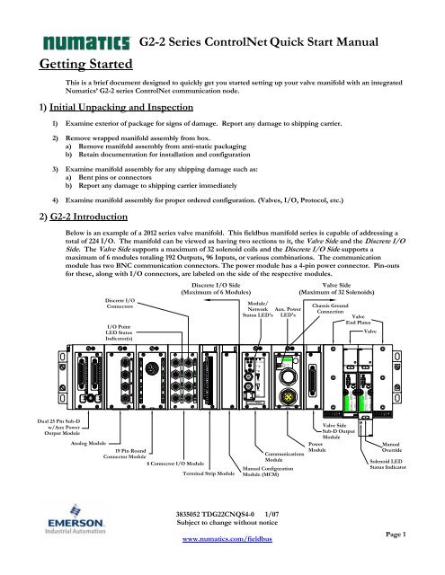
2) G2-2 Introduction<br />
Below is an example of a 2012 series valve manifold. This fieldbus manifold series is capable of addressing a<br />
total of 224 I/O. The manifold can be viewed as having two sections to it, the Valve Si<strong>de</strong> and the Discrete I/O<br />
Si<strong>de</strong>. The Valve Si<strong>de</strong> supports a maximum of 32 solenoid coils and the Discrete I/O Si<strong>de</strong> supports a<br />
maximum of 6 modules totaling 192 Outputs, 96 Inputs, or various combinations. The communication<br />
module has two BNC communication connectors. The power module has a 4-pin power connector. Pin-outs<br />
for these, along with I/O connectors, are labeled on the si<strong>de</strong> of the respective modules.<br />
Valve Si<strong>de</strong><br />
(Maximum of 32 Solenoids)<br />
Module/<br />
Network<br />
Status LED's<br />
3835052 TDG22CNQS4-0 1/07<br />
Subject to change without notice<br />
www.numatics.com/fieldbus<br />
Aux. Power<br />
LED's<br />
Communications<br />
Module<br />
Chassis Ground<br />
Connection<br />
Valve<br />
End Plates<br />
Valve<br />
Valve Si<strong>de</strong><br />
Sub-D Output<br />
Module<br />
Power<br />
Module<br />
Manual<br />
Overri<strong>de</strong><br />
Solenoid LED<br />
Status Indicator<br />
Page 1
G2-2 Series ControlNet Quick Start Manual<br />
3) MCM - Manual Configuration Module (for Self-Test Mo<strong>de</strong> Function Only)<br />
Rotary Switch<br />
(SW3)<br />
Rotary Switch<br />
(SW4)<br />
ON<br />
DIP Switch<br />
(SW2)<br />
1 2 3 4 5 6 7 8<br />
DIP Switch<br />
(SW1)<br />
1 2 3 4 5 6 7 8<br />
All DIP switches shown in the "OFF" position<br />
The MCM is the module that allows the user to manually test the <strong>Numatics</strong> manifold using Self-Test mo<strong>de</strong>.<br />
The MCM consists of two DIP switch sets (SW1 and SW2) and two rotary switches (SW3 and SW4).<br />
MCM Module Part Numbers<br />
Description Part Number<br />
Complete Module 239-1384<br />
Replacement Board 256-684<br />
ON<br />
3835052 TDG22CNQS4-0 1/07<br />
Subject to change without notice<br />
www.numatics.com/fieldbus<br />
Page 2
4) Self-Test Mo<strong>de</strong><br />
G2-2 Series ControlNet Quick Start Manual<br />
An internal diagnostic tool can also be enabled using the optional MCM module. This tool allows the user to<br />
confirm that all of the Inputs and Outputs on the manifold are fully functional without needing a network<br />
connection or controller. There are two test mo<strong>de</strong>s that the user can choose using SW2-8. The “Output” test<br />
mo<strong>de</strong> tests all the outputs by sequentially turning them ON one at a time. The “Input/Output” test mo<strong>de</strong><br />
tests the inputs by causing all of the outputs to toggle between even and odd values when any input is ma<strong>de</strong>.<br />
To use the Self-Test Mo<strong>de</strong>, the user must first set some initial conditions using the MCM module. Follow<br />
these steps to obtain the nee<strong>de</strong>d initial condition settings. Remember to remove power from the manifold<br />
before making changes to the MCM when setting these initial conditions.<br />
1) Disconnect power and air from the manifold!<br />
2) Record current MCM settings.<br />
3) Set the rotary switches to 99 (SW3 and SW4).<br />
4) Make sure that SW1-5, SW2-1, and SW2-7 are in the “ON” position.<br />
5) Select the <strong>de</strong>sired test mo<strong>de</strong> with SW2-8 (see table below)<br />
Switch Testing<br />
Setting<br />
Mo<strong>de</strong><br />
Description<br />
Output Off Sequentially turns all the outputs ON and OFF.<br />
SW2-8 Input/<br />
Output On<br />
Causes all of the odd outputs to come on and stay on until an<br />
input is ma<strong>de</strong>. When an input is ma<strong>de</strong>, the outputs will toggle to<br />
the even outputs.<br />
6) Make sure that all of the other switches are in the “OFF” position.<br />
The initial conditions are now set. To enable the Self-Test Mo<strong>de</strong>, apply power to the manifold and make the<br />
following changes within 5 to 10 seconds:<br />
1) Set SW2-6 to the “ON” position.<br />
2) Set SW2-7 to the “OFF” position.<br />
Self-Test Mo<strong>de</strong> is terminated by removing power to the unit. Remember to return the MCM settings to their<br />
original settings to return the communication no<strong>de</strong> to normal operation.<br />
!<br />
Air should be disconnected to the manifold when attempting to run the<br />
Self-Test Mo<strong>de</strong> to prevent unwanted motion.<br />
Communication lines should be disconnected before attempting to run the<br />
Self-Test Mo<strong>de</strong>.<br />
3835052 TDG22CNQS4-0 1/07<br />
Subject to change without notice<br />
www.numatics.com/fieldbus<br />
Page 3
5) Communication Module Rotary Switches<br />
G2-2 Series ControlNet Quick Start Manual<br />
The Rotary switches allow the user to set the no<strong>de</strong> address.<br />
Rotary Switch Settings<br />
Network Address:<br />
!<br />
Switch Description<br />
NA 01 Sets the Ones Digits<br />
NA 10 Sets the Tens Digits<br />
Address is set to a <strong>de</strong>fault setting of 00 prior to shipment.<br />
Rotary switch settings do not take effect until power is cycled (turned<br />
OFF and ON).<br />
3835052 TDG22CNQS4-0 1/07<br />
Subject to change without notice<br />
www.numatics.com/fieldbus<br />
Page 4
6) I/O Mapping Example<br />
Example:<br />
Assumed Settings<br />
- Single Z-Boards TM used with single solenoid valves<br />
- Double Z-Boards TM used with double solenoid<br />
valves<br />
- Run Idle Hea<strong>de</strong>r (Overhead) will always take up<br />
the first two Input words of the Input Map.<br />
Discrete I/O Configuration<br />
Pos<br />
Module Type<br />
No.<br />
Part No.<br />
In Out<br />
Bytes<br />
1 MCM 239-1384 -- --<br />
2<br />
8O Sourcing<br />
(PNP)<br />
239-1315 1 1<br />
3<br />
16O Sourcing<br />
(PNP)<br />
239-1319 1 2<br />
4<br />
4I Sinking<br />
(NPN)<br />
239-1304 1 0<br />
5<br />
8I Sinking<br />
(NPN)<br />
239-1308 1 0<br />
Manifold I/O Configuration<br />
Outputs and Mapping Location<br />
Valve Outputs = 12 Word 0; Bits 0-11<br />
Allocated Unused Word 0; Bits 12-15<br />
Valve Outputs = 20 Word 1; Bits 0-15<br />
Discrete<br />
Word 2; Bits 0-15<br />
Outputs = 24<br />
Total Outputs = 56<br />
Word 3; Bits 0-7<br />
Inputs and Mapping Location<br />
Discrete Inputs = 12 Word 5; Bits 0-3, 8-15<br />
Allocated and<br />
Word 5; Bits 4-7<br />
Reserved Inputs = 4<br />
Total Inputs = 16<br />
G2-2 Series ControlNet Quick Start Manual<br />
3835052 TDG22CNQS4-0 1/07<br />
Subject to change without notice<br />
www.numatics.com/fieldbus<br />
Page 5
I/O Mapping Table Example Continued<br />
WORD BYTE<br />
0<br />
1<br />
2<br />
0<br />
1<br />
2<br />
3<br />
4<br />
5<br />
3 6<br />
WORD BYTE<br />
0<br />
1<br />
2<br />
3<br />
4<br />
5<br />
0<br />
1<br />
2<br />
3<br />
4<br />
5<br />
6<br />
7<br />
8<br />
9<br />
10<br />
11<br />
G2-2 Series ControlNet Quick Start Manual<br />
Output Table<br />
BIT<br />
7 15 6 14 5 13 4 12 3 11 2 10 1 9 0 8<br />
Valve Coil<br />
No. 8<br />
Allocated &<br />
Reserved<br />
Allocated &<br />
Reserved<br />
Allocated &<br />
Reserved<br />
Discrete<br />
Output No. 7<br />
Discrete<br />
Output No. 7<br />
Discrete<br />
Output No. 15<br />
Valve Coil<br />
No. 7<br />
Allocated &<br />
Reserved<br />
Allocated &<br />
Reserved<br />
Allocated &<br />
Reserved<br />
Discrete<br />
Output No. 6<br />
Discrete<br />
Output No. 6<br />
Discrete<br />
Output No. 14<br />
Valve Coil<br />
No. 6<br />
Allocated &<br />
Reserved<br />
Allocated &<br />
Reserved<br />
Allocated &<br />
Reserved<br />
Discrete<br />
Output No. 5<br />
Discrete<br />
Output No. 5<br />
Discrete<br />
Output No. 13<br />
Valve Coil<br />
No. 5<br />
Allocated &<br />
Reserved<br />
Allocated &<br />
Reserved<br />
Allocated &<br />
Reserved<br />
Discrete<br />
Output No. 4<br />
Discrete<br />
Output No. 4<br />
Discrete<br />
Output No. 12<br />
3835052 TDG22CNQS4-0 1/07<br />
Subject to change without notice<br />
www.numatics.com/fieldbus<br />
Valve Coil<br />
No. 4<br />
Valve Coil<br />
No. 12<br />
Allocated &<br />
Reserved<br />
Allocated &<br />
Reserved<br />
Discrete<br />
Output No. 3<br />
Discrete<br />
Output No. 3<br />
Discrete<br />
Output No. 11<br />
Valve Coil<br />
No. 3<br />
Valve Coil<br />
No. 11<br />
Allocated &<br />
Reserved<br />
Allocated &<br />
Reserved<br />
Discrete<br />
Output No. 2<br />
Discrete<br />
Output No. 2<br />
Discrete<br />
Output No. 10<br />
Valve Coil<br />
No. 2<br />
Valve Coil<br />
No. 10<br />
Allocated &<br />
Reserved<br />
Allocated &<br />
Reserved<br />
Discrete<br />
Output No. 1<br />
Discrete<br />
Output No. 1<br />
Discrete<br />
Output No. 9<br />
Valve Coil<br />
No. 1<br />
Valve Coil<br />
No. 9<br />
Allocated &<br />
Reserved<br />
Allocated &<br />
Reserved<br />
Discrete<br />
Output No. 0<br />
Discrete<br />
Output No. 0<br />
Discrete<br />
Output No. 8<br />
Input Table<br />
BIT<br />
7 15 6 14 5 13 4 12 3 11 2 10 1 9 0 8<br />
Run Idle<br />
Hea<strong>de</strong>r<br />
Run Idle<br />
Hea<strong>de</strong>r<br />
Run Idle<br />
Hea<strong>de</strong>r<br />
Run Idle<br />
Hea<strong>de</strong>r<br />
Coil No. 8<br />
Status<br />
Coil No. 16<br />
Status<br />
Coil No. 24<br />
Status<br />
Coil No. 32<br />
Status<br />
Allocated &<br />
Reserved<br />
Allocated &<br />
Reserved<br />
Allocated &<br />
Reserved<br />
Discrete<br />
Input No. 7<br />
Run Idle<br />
Hea<strong>de</strong>r<br />
Run Idle<br />
Hea<strong>de</strong>r<br />
Run Idle<br />
Hea<strong>de</strong>r<br />
Run Idle<br />
Hea<strong>de</strong>r<br />
Coil No. 7<br />
Status<br />
Coil No. 15<br />
Status<br />
Coil No. 23<br />
Status<br />
Coil No. 31<br />
Status<br />
Allocated &<br />
Reserved<br />
Allocated &<br />
Reserved<br />
Allocated &<br />
Reserved<br />
Discrete<br />
Input No. 6<br />
1 Byte = 8 Bits<br />
Run Idle<br />
Hea<strong>de</strong>r<br />
Run Idle<br />
Hea<strong>de</strong>r<br />
Run Idle<br />
Hea<strong>de</strong>r<br />
Run Idle<br />
Hea<strong>de</strong>r<br />
Coil No. 6<br />
Status<br />
Coil No. 14<br />
Status<br />
Coil No. 22<br />
Status<br />
Coil No. 30<br />
Status<br />
Allocated &<br />
Reserved<br />
Allocated &<br />
Reserved<br />
Allocated &<br />
Reserved<br />
Discrete<br />
Input No. 5<br />
1 Word = 2 Bytes or 16 Bits<br />
Run Idle<br />
Hea<strong>de</strong>r<br />
Run Idle<br />
Hea<strong>de</strong>r<br />
Run Idle<br />
Hea<strong>de</strong>r<br />
Run Idle<br />
Hea<strong>de</strong>r<br />
Coil No. 5<br />
Status<br />
Coil No. 13<br />
Status<br />
Coil No. 21<br />
Status<br />
Coil No. 29<br />
Status<br />
Allocated &<br />
Reserved<br />
Allocated &<br />
Reserved<br />
Allocated &<br />
Reserved<br />
Discrete<br />
Input No. 4<br />
Run Idle<br />
Hea<strong>de</strong>r<br />
Run Idle<br />
Hea<strong>de</strong>r<br />
Run Idle<br />
Hea<strong>de</strong>r<br />
Run Idle<br />
Hea<strong>de</strong>r<br />
Coil No. 4<br />
Status<br />
Coil No. 12<br />
Status<br />
Coil No. 20<br />
Status<br />
Coil No. 28<br />
Status<br />
Allocated &<br />
Reserved<br />
Status for<br />
Discrete<br />
Outputs<br />
No.12-15<br />
Discrete<br />
Input No. 3<br />
Discrete<br />
Input No. 3<br />
Run Idle<br />
Hea<strong>de</strong>r<br />
Run Idle<br />
Hea<strong>de</strong>r<br />
Run Idle<br />
Hea<strong>de</strong>r<br />
Run Idle<br />
Hea<strong>de</strong>r<br />
Coil No. 3<br />
Status<br />
Coil No. 11<br />
Status<br />
Coil No. 19<br />
Status<br />
Coil No. 27<br />
Status<br />
Allocated &<br />
Reserved<br />
Status for<br />
Discrete<br />
Outputs<br />
No. 8-11<br />
Discrete<br />
Input No. 2<br />
Discrete<br />
Input No. 2<br />
Run Idle<br />
Hea<strong>de</strong>r<br />
Run Idle<br />
Hea<strong>de</strong>r<br />
Run Idle<br />
Hea<strong>de</strong>r<br />
Run Idle<br />
Hea<strong>de</strong>r<br />
Coil No. 2<br />
Status<br />
Coil No. 10<br />
Status<br />
Coil No. 18<br />
Status<br />
Coil No. 26<br />
Status<br />
Status for<br />
Discrete<br />
Outputs<br />
No. 4-7<br />
Status for<br />
Discrete<br />
Outputs<br />
No. 4-7<br />
Discrete<br />
Input No. 1<br />
Discrete<br />
Input No. 1<br />
Page 6<br />
Run Idle<br />
Hea<strong>de</strong>r<br />
Run Idle<br />
Hea<strong>de</strong>r<br />
Run Idle<br />
Hea<strong>de</strong>r<br />
Run Idle<br />
Hea<strong>de</strong>r<br />
Coil No. 1<br />
Status<br />
Coil No. 9<br />
Status<br />
Coil No. 17<br />
Status<br />
Coil No. 25<br />
Status<br />
Status for<br />
Discrete<br />
Outputs<br />
No. 0-3<br />
Status for<br />
Discrete<br />
Outputs<br />
No. 0-3<br />
Discrete<br />
Input No. 0<br />
Discrete<br />
Input No. 0
G2-2 Series ControlNet Quick Start Manual<br />
7) Output Short Circuit Protection (Status Input Bits)<br />
Status Input Bits report the integrity of the load being driven by the output driver. They must be mapped to the<br />
scanner as part of the Input Size Value. Please refer to the table below for Status Input Bit action during fault<br />
condition:<br />
Output Type Output State Fault Condition Status Bit<br />
Valve Solenoid Coil Driver or<br />
Sinking (NPN)<br />
Discrete Outputs<br />
ON<br />
OFF<br />
No Fault<br />
Fault - Short Circuit, Over Temp/Over Current<br />
No Fault<br />
Fault - Open Load<br />
0<br />
1<br />
0<br />
1<br />
Sourcing (PNP)<br />
Discrete Outputs<br />
ON<br />
No Fault<br />
Fault - Short Circuit, Over Temp/Over Current<br />
0<br />
1<br />
8) Ground Wiring<br />
All <strong>Numatics</strong> Inc. communication no<strong>de</strong>s should be groun<strong>de</strong>d during the installation process. These grounding<br />
gui<strong>de</strong>lines can be found in National Electrical co<strong>de</strong> IEC 60204-1 or EN 60204-1. There also is a,<br />
“ATTENTION: CONNECT TO EARTH GROUND FOR PROPER GROUNDING OF UNIT”, label<br />
attached to the chassis ground connection point on the G2-2 series communication no<strong>de</strong> housing. This label<br />
also points out where the grounding gui<strong>de</strong>lines can be found.<br />
!<br />
Proper grounding will alleviate and prevent many intermittent problems<br />
with network communication.<br />
When grounding to a machine frame, please ensure that the machine frame<br />
itself is already properly groun<strong>de</strong>d.<br />
Better grounding can be achieved when larger diameter (lower gauge) wire<br />
is used.<br />
3835052 TDG22CNQS4-0 1/07<br />
Subject to change without notice<br />
www.numatics.com/fieldbus<br />
Page 7
9) Auxiliary Power Connector Pin-Out<br />
!<br />
G2-2 Series ControlNet Quick Start Manual<br />
Pin No. Function Description<br />
1<br />
+24VDC<br />
(Valves and Outputs)<br />
Voltage Used to Power Outputs<br />
(Valve Coils and Discrete Outputs)<br />
2 Earth Ground Protective Earth (Case Ground)<br />
3 0VDC Common 0VDC Common, for Valves, I/O, and No<strong>de</strong> Power<br />
4<br />
+24VDC<br />
(No<strong>de</strong> and Inputs)<br />
Voltage Used to Power Discrete Inputs and No<strong>de</strong> Electronics<br />
4<br />
1 3<br />
2<br />
Maximum current capacity on the 0VDC common pin of the auxiliary<br />
power connector is 8 Amps. The combined draw of the +24VDC Valves and<br />
Outputs and +24VDC No<strong>de</strong> and Inputs pins cannot exceed 8 Amps, at any<br />
given moment in time.<br />
The auxiliary power +24VDC No<strong>de</strong> and Inputs pin supplies power to the<br />
no<strong>de</strong> electronics. This pin must be powered at all times for communication<br />
no<strong>de</strong> to be functional.<br />
3835052 TDG22CNQS4-0 1/07<br />
Subject to change without notice<br />
www.numatics.com/fieldbus<br />
Page 8
10) LED Functions<br />
G2-2 Series ControlNet Quick Start Manual<br />
Upon power up, the LEDs indicate the status of the unit. The Power Module of the G2-2 ControlNet no<strong>de</strong> has<br />
four LEDs; two for internal fuse integrity and two for Aux. Power status. The Communication module also<br />
has four status LEDs which are <strong>de</strong>scribed below.<br />
Communication Module<br />
LED Name Color Status Description<br />
Off OFF Module is not initialized<br />
Green Red FLASHING Self test of bus controller<br />
MS<br />
(Module Status)<br />
OWNED<br />
(Module Owned)<br />
Red<br />
ON<br />
FLASHING<br />
Faulted unit, must be restarted<br />
Incorrect no<strong>de</strong> configuration; i.e. duplicate MAC ID<br />
Off OFF Channel is disabled, <strong>de</strong>pending on the network configuration<br />
ON Normal operation of channel<br />
Green<br />
FLASHING<br />
Temporary errors (no<strong>de</strong> will self correct) or no<strong>de</strong> is not configured to<br />
go online<br />
Red FLASHING Media Fault or no other no<strong>de</strong>s on the network<br />
Green Red FLASHING Incorrect network configuration<br />
Green<br />
ON<br />
FLASHING<br />
Module is initialized<br />
Module is waiting for initialization<br />
Red<br />
ON<br />
FLASHING<br />
Major fault, module must be restarted<br />
Minor fault, MAC ID has been changed after initialization, etc.<br />
Green<br />
OFF<br />
ON<br />
No connection is opened<br />
A connection is opened to the module<br />
Power Module<br />
LED Name Color Status Description<br />
FUSE 1 Red<br />
+24V VLV/OUT Green<br />
FUSE 2 Red<br />
+24V NODE/IN Green<br />
OFF<br />
Internal fuse F1 is OK (valid only when power is applied to<br />
+24V VLV / OUT pin on Aux. Power connector).<br />
ON<br />
Internal fuse F1 is open; No power is internally provi<strong>de</strong>d to valves or<br />
outputs. Communication NOT affected.<br />
OFF No DC Power present at +24V VLV / OUT pin on Aux. Power connector.<br />
ON DC Power applied to +24V VLV / OUT pin on Aux. Power Connector.<br />
OFF<br />
Internal fuse F2 is OK (valid only when power is applied to<br />
+24V NODE / IN pin on Aux. Power connector.<br />
ON<br />
Internal fuse F2 is open; No power is internally provi<strong>de</strong>d to no<strong>de</strong><br />
electronics or inputs. Communication No<strong>de</strong> will not function.<br />
OFF No DC Power present at +24V NODE / IN pin on Aux. Power connector.<br />
ON DC Power applied to+24V NODE / IN pin on Aux. Power connector.<br />
3835052 TDG22CNQS4-0 1/07<br />
Subject to change without notice<br />
www.numatics.com/fieldbus<br />
Page 9
11) Configuration with RSLOGIX 5000<br />
G2-2 Series ControlNet Quick Start Manual<br />
When commissioning your ControlNet no<strong>de</strong>, specific values must be entered in the “Connection Parameters”<br />
section for the “Assembly Instance” column with regards to “Input Size”, “Output Size”, and<br />
“Configuration”. The “Size” values are <strong>de</strong>termined from the actual physical configuration of the manifold<br />
(i.e. how many and which I/O modules are installed on the manifold). The size values are a minimum value;<br />
higher values can be used if future manifold I/O expansion is required. Below is a sample screen shot taken<br />
from Allen Bradley’s RSLogix 5000 programming software, it shows where the appropriate values for the<br />
No<strong>de</strong> Address, Assembly Instance, Size and Configuration must be entered.<br />
Module Properties<br />
Comm. Format:<br />
Connection Parameters:<br />
Description Data<br />
Comm. Format “Data – INT”<br />
Description<br />
Input<br />
Output<br />
Configuration<br />
Assembly Instance<br />
Values<br />
100 (Decimal) or<br />
64 (Hexa<strong>de</strong>cimal)<br />
150 (Decimal) or<br />
96 (Hexa<strong>de</strong>cimal)<br />
1 (Decimal) or<br />
1 (Hexi<strong>de</strong>cimal)<br />
3835052 TDG22CNQS4-0 1/07<br />
Subject to change without notice<br />
www.numatics.com/fieldbus<br />
Size (16 Bits=1 Word)<br />
Total Input Size value (in words) from manifold<br />
configuration (including status Input bits) + 2 Words<br />
of ControlNet Run/Idle Hea<strong>de</strong>r (overhead). This is a<br />
minimum value; larger values may be specified for<br />
future expansion purposes.<br />
Total Output Size value (in words) from manifold<br />
configuration. This is a minimum value; larger values<br />
may be specified for future expansion purposes.<br />
0<br />
Page 10
12) Factory Default Settings<br />
G2-2 Series ControlNet Quick Start Manual<br />
Unless otherwise requested, all standard G2-2 Series ControlNet manifolds ship with specific factory <strong>de</strong>fault<br />
settings. Below is a list of the factory <strong>de</strong>fault settings:<br />
13) Technical Support<br />
Description Default Settings<br />
No<strong>de</strong> Address 0<br />
Baud Rate 5 Mbit/sec<br />
Input Module Power Jumper<br />
PU<br />
(Input sensor power supplied by<br />
+24VDC No<strong>de</strong> and Inputs pin on the Aux. power connector)<br />
Output Module Power Jumper<br />
SP<br />
(Output module power supplied by<br />
+24VDC Valves and Outputs pin on the Aux. power connector)<br />
Valve Si<strong>de</strong> Output Bytes 4 Bytes (32 Allocated Valve Coil Outputs)<br />
Discrete I/O Si<strong>de</strong> - I/O Bytes Self-Configuring based on the I/O modules installed.<br />
For technical support, contact your local <strong>Numatics</strong> distributor. If further information is required,<br />
please call <strong>Numatics</strong> Inc. at (248) 887-4111 and ask for Technical Support.<br />
Issues relating to network set-up, PLC programming, sequencing, software related functions, etc…<br />
should be handled with the appropriate product vendor.<br />
Information on <strong>de</strong>vice files, technical manuals, local distributors, and other <strong>Numatics</strong>, Inc. products<br />
and support issues can be found on the <strong>Numatics</strong>, Inc’s WEB site at www.numatics.com<br />
For general help or more information regarding the fieldbus you may access the ControlNet International<br />
homepage found at www.controlnet.org<br />
3835052 TDG22CNQS4-0 1/07<br />
Subject to change without notice<br />
www.numatics.com/fieldbus<br />
Page 11
Pour commencer<br />
<strong>Gui<strong>de</strong></strong> <strong>de</strong> <strong>Démarrage</strong> Rapi<strong>de</strong><br />
<strong>Série</strong> 2-2 - ControlNet<br />
Ce document décrit le démarrage rapi<strong>de</strong> <strong>de</strong> votre îlot <strong>de</strong> distribution à nœud <strong>de</strong> communication ControlNet<br />
série G2-2 intégré.<br />
1) Déballage et inspection<br />
1) Inspectez l'emballage extérieur pour détecter tout dommage. Tout dommage constaté doit être signalé au<br />
transporteur.<br />
2) Retirez l'ensemble <strong>de</strong> l'îlot <strong>de</strong> son carton.<br />
a) Sortez l'ensemble <strong>de</strong> son emballage anti-statique.<br />
b) Conservez la documentation portant sur l'installation et la configuration.<br />
3) Inspectez l'ensemble <strong>de</strong> l'îlot pour détecter tout dommage <strong>de</strong> transport tel que:<br />
a) Broches ou connecteurs déformés<br />
b) Tout dommage constaté doit être immédiatement signalé au transporteur.<br />
4) Vérifiez que la configuration <strong>de</strong> l'ensemble <strong>de</strong> l'îlot livré correspond à votre comman<strong>de</strong>. (distributeurs, E/S,<br />
protocole, …).<br />
2) Introduction à la série G2-2<br />
Ci-<strong>de</strong>ssous un exemple représentant l'ensemble d'un îlot <strong>de</strong> distributeurs <strong>de</strong> la série 2012. Cette série d'îlots à<br />
bus <strong>de</strong> terrain est capable d'adresser un total <strong>de</strong> 224 E/S. L'îlot peut être considéré comme ayant <strong>de</strong>ux parties:<br />
la partie Composants pneumatiques et la partie Composants électroniques. La partie Composants<br />
pneumatiques supporte un maximum <strong>de</strong> 32 bobines et la partie Composants électroniques supporte un<br />
maximum <strong>de</strong> 6 modules, donc un total <strong>de</strong> 192 sorties, 96 entrées ou <strong>de</strong> différentes combinaisons <strong>de</strong> celles-ci.<br />
Le module <strong>de</strong> communication est équipé <strong>de</strong> <strong>de</strong>ux connecteurs <strong>de</strong> communication BNC. Le module<br />
d'alimentation en tension est équipé d'un connecteur d'alimentation à 4 broches. L'affectation <strong>de</strong>s broches<br />
ainsi que les connecteurs E/S sont repérés sur la face latérale <strong>de</strong> chaque module. Valve Si<strong>de</strong><br />
(Maximum of 32 Solenoids)<br />
Module/<br />
Network<br />
Status LED's<br />
Aux. Power<br />
LED's<br />
Communications<br />
Module<br />
3835052 TDG22CNQS4-0 1/07<br />
Sous réserve <strong>de</strong> modification sans avis préalable<br />
www.numatics.com/fieldbus<br />
Chassis Ground<br />
Connection<br />
Valve<br />
End Plates<br />
Valve<br />
Valve Si<strong>de</strong><br />
Sub-D Output<br />
Module<br />
Power<br />
Module<br />
Manual<br />
Overri<strong>de</strong><br />
Solenoid LED<br />
Status Indicator<br />
Page 1
<strong>Gui<strong>de</strong></strong> <strong>de</strong> <strong>Démarrage</strong> Rapi<strong>de</strong><br />
<strong>Série</strong> 2-2 - ControlNet<br />
3) MCM – Module <strong>de</strong> configuration manuelle (uniquement pour la fonction du mo<strong>de</strong><br />
auto-test)<br />
Rotary Switch<br />
(SW3)<br />
Rotary Switch<br />
(SW4)<br />
ON<br />
DIP Switch<br />
(SW2)<br />
1 2 3 4 5 6 7 8<br />
DIP Switch<br />
(SW1)<br />
1 2 3 4 5 6 7 8<br />
All DIP switches shown in the "OFF" position<br />
Le MCM (module <strong>de</strong> configuration manuelle) permet à l'utilisateur <strong>de</strong> tester manuellement l'îlot <strong>Numatics</strong> en<br />
utilisant le mo<strong>de</strong> auto-test. Le MCM est équipé <strong>de</strong> <strong>de</strong>ux ensembles <strong>de</strong> DIP switchs (SW1 et SW2) et <strong>de</strong> <strong>de</strong>ux<br />
roues co<strong>de</strong>uses (SW3 et SW4).<br />
Co<strong>de</strong>s <strong>de</strong>s composants du module MCM<br />
Description Co<strong>de</strong><br />
Module complet 239-1384<br />
Carte <strong>de</strong> rechange 256-684<br />
3835052 TDG22CNQS4-0 1/07<br />
Sous réserve <strong>de</strong> modification sans avis préalable<br />
www.numatics.com/fieldbus<br />
ON<br />
Page 2
4) Mo<strong>de</strong> auto-test<br />
<strong>Gui<strong>de</strong></strong> <strong>de</strong> <strong>Démarrage</strong> Rapi<strong>de</strong><br />
<strong>Série</strong> 2-2 - ControlNet<br />
Un outil diagnostic interne peut également être activé par le module MCM optionnel. Cet outil permet à<br />
l'utilisateur <strong>de</strong> s'assurer que toutes les entrées et sorties sur l'îlot sont complètement opérationnelles, sans<br />
besoin <strong>de</strong> connexion réseau, ni <strong>de</strong> contrôleur. Le switch SW2-8 permet à l'utilisateur <strong>de</strong> choisir entre <strong>de</strong>ux<br />
mo<strong>de</strong>s test. Le mo<strong>de</strong> test “Entrée/Sortie” teste les entrées <strong>de</strong> sorte que toutes les sorties commutent entre les<br />
valeurs paires et impaires lorsqu'un signal d'entrée est appliqué.<br />
Pour utiliser le mo<strong>de</strong> auto-test, l'utilisateur doit, tout d'abord, paramétrer quelques conditions initiales au<br />
moyen du module MCM. Suivre les étapes suivantes pour obtenir les réglages <strong>de</strong>s conditions initiales requises.<br />
Lors du paramétrage <strong>de</strong>s conditions initiales, n'oubliez pas <strong>de</strong> couper l'alimentation électrique <strong>de</strong> l'îlot avant<br />
d'effectuer les modifications sur le MCM.<br />
1) Couper l'alimentation électrique et pneumatique <strong>de</strong> l'îlot!<br />
2) Enregistrez les réglages actuels du MCM.<br />
3) Positionnez les roues co<strong>de</strong>uses sur 99 (SW3 et SW4).<br />
4) Assurez-vous que les switchs SW1-5, SW2-1 et SW2-7 sont sur la position “ON”.<br />
5) Sélectionnez le mo<strong>de</strong> test désiré à l'ai<strong>de</strong> du switch SW2-8 (voir le tableau ci-<strong>de</strong>ssous).<br />
Switch Mo<strong>de</strong><br />
test<br />
Sortie Off<br />
SW2-8 Entrée/<br />
Sortie<br />
Réglage Description<br />
On<br />
Les sorties sont successivement mises sous tension (ON), puis<br />
hors tension (OFF).<br />
Les sorties impaires sont mises sous tension et restent sous<br />
tension jusqu'à ce qu'un signal d'entrée est appliqué. Lorsqu'un<br />
signal d'entrée est appliqué, les sorties commutent sur les sorties<br />
paires.<br />
6) Assurez-vous que tous les autres switchs sont sur la position “OFF”.<br />
Le réglage <strong>de</strong>s condition initiales est alors terminé. Pour activer le mo<strong>de</strong> auto-test, mettez l'îlot sous tension et<br />
faites les modifications suivantes pendant les premières 5 à 10 secon<strong>de</strong>s :<br />
1) Placez le switch SW2-6 sur la position “ON”.<br />
2) Placez le switch SW2-7 sur la position “OFF”.<br />
Le mo<strong>de</strong> auto-test est terminé en coupant l'alimentation en tension <strong>de</strong> l'îlot. N'oubliez pas <strong>de</strong> remettre les<br />
réglages d'origine du MCM pour remettre le nœud <strong>de</strong> communication en fonctionnement régulier.<br />
!<br />
Avant <strong>de</strong> lancer le mo<strong>de</strong> auto-test, coupez l'alimentation en air <strong>de</strong> l'îlot pour<br />
prévenir les mouvements acci<strong>de</strong>ntels.<br />
Débranchez les câbles <strong>de</strong> communication avant <strong>de</strong> lancer le mo<strong>de</strong> auto-test.<br />
3835052 TDG22CNQS4-0 1/07<br />
Sous réserve <strong>de</strong> modification sans avis préalable<br />
www.numatics.com/fieldbus<br />
Page 3
<strong>Gui<strong>de</strong></strong> <strong>de</strong> <strong>Démarrage</strong> Rapi<strong>de</strong><br />
<strong>Série</strong> 2-2 - ControlNet<br />
5) Roues co<strong>de</strong>uses du module <strong>de</strong> communication<br />
Les roues co<strong>de</strong>uses permettent à l'utilisateur <strong>de</strong> régler l'adresse du nœud.<br />
Réglages <strong>de</strong>s roues co<strong>de</strong>uses<br />
Adresse du réseau :<br />
!<br />
Switch Description<br />
NA 01 Mise au point <strong>de</strong>s chiffres <strong>de</strong>s unités<br />
NA 10 Mise au point <strong>de</strong>s chiffres <strong>de</strong>s dizaines<br />
L'adresse réglée en usine est <strong>de</strong> 00 par défaut.<br />
Les réglages <strong>de</strong>s roues co<strong>de</strong>uses ne prennent effet qu'au prochain cycle <strong>de</strong> mise<br />
sous tension (mise hors tension et mise sous tension).<br />
3835052 TDG22CNQS4-0 1/07<br />
Sous réserve <strong>de</strong> modification sans avis préalable<br />
www.numatics.com/fieldbus<br />
Page 4
6) Exemple <strong>de</strong> mapping <strong>de</strong>s E/S<br />
Exemple:<br />
Assumed Settings<br />
- Cartes Z-Boards TM simples utilisées avec les<br />
électrodistributeurs simples.<br />
- Cartes Z-Boards TM doubles utilisées avec les<br />
électrodistributeurs doubles.<br />
- Run Idle Hea<strong>de</strong>r (surcharge exécuter/état inactif)<br />
reprend toujours les <strong>de</strong>ux premiers mots d'entrée<br />
du map d'entrée.<br />
Configuration <strong>de</strong>s E/S discrètes<br />
No.<br />
<strong>de</strong><br />
pos<br />
Type <strong>de</strong><br />
module<br />
Co<strong>de</strong><br />
<strong>Gui<strong>de</strong></strong> <strong>de</strong> <strong>Démarrage</strong> Rapi<strong>de</strong><br />
<strong>Série</strong> 2-2 - ControlNet<br />
In Out<br />
Octets<br />
1 MCM 239-1384 -- --<br />
2<br />
8O Sourcing<br />
(PNP)<br />
239-1315 1 1<br />
3<br />
16O Sourcing<br />
(PNP)<br />
239-1319 1 2<br />
4<br />
4I Sinking<br />
(NPN)<br />
239-1304 1 0<br />
5<br />
8I Sinking<br />
(NPN)<br />
239-1308 1 0<br />
Configuration <strong>de</strong>s E/S <strong>de</strong> l'îlot<br />
Allocation sorties et mapping<br />
Sorties distr. = 12 Mot 0; Bits 0-11<br />
Sorties distr. allouées Mot 0; Bits 12-15<br />
non-utilisées = 20 Mot 1; Bits 0-15<br />
Mot 2; Bits 0-15<br />
Sorties discrètes = 24<br />
Mot 3; Bits 0-7<br />
Nb. total <strong>de</strong> sorties =<br />
56<br />
Allocation entrées et mapping<br />
Entrées discrètes = 12 Mot 5; Bits 0-3, 8-15<br />
Entrées allouées et<br />
Mot 5; Bits 4-7<br />
réservées = 4<br />
Nb. total d'entrées = 16<br />
3835052 TDG22CNQS4-0 1/07<br />
Sous réserve <strong>de</strong> modification sans avis préalable<br />
www.numatics.com/fieldbus<br />
Page 5
<strong>Gui<strong>de</strong></strong> <strong>de</strong> <strong>Démarrage</strong> Rapi<strong>de</strong><br />
<strong>Série</strong> 2-2 - ControlNet<br />
Exemple <strong>de</strong> mapping <strong>de</strong>s E/S - continuation<br />
MOT Octet<br />
0<br />
1<br />
2<br />
Tableau <strong>de</strong>s sorties<br />
BIT<br />
7 15 6 14 5 13 4 12 3 11 2 10 1 9 0 8<br />
0 Bobine no. 8 Bobine no. 7 Bobine no. 6 Bobine no. 5 Bobine no. 4 Bobine no. 3 Bobine no. 2 Bobine no. 1<br />
1<br />
2<br />
3<br />
3 6<br />
Mot Octet<br />
0<br />
1<br />
2<br />
3<br />
4<br />
5<br />
Alloué et<br />
réservé<br />
Alloué et<br />
réservé<br />
Alloué et<br />
réservé<br />
Alloué et<br />
réservé<br />
Alloué et<br />
réservé<br />
Alloué et<br />
réservé<br />
Alloué et<br />
réservé<br />
Alloué et<br />
réservé<br />
Alloué et<br />
réservé<br />
Alloué et<br />
réservé<br />
Alloué et<br />
réservé<br />
Alloué et<br />
réservé<br />
3835052 TDG22CNQS4-0 1/07<br />
Sous réserve <strong>de</strong> modification sans avis préalable<br />
www.numatics.com/fieldbus<br />
Bobine no. 12 Bobine no. 11 Bobine no. 10 Bobine no. 9<br />
Alloué et<br />
réservé<br />
Alloué et<br />
réservé<br />
Alloué et<br />
réservé<br />
Alloué et<br />
réservé<br />
Alloué et<br />
réservé<br />
Alloué et<br />
réservé<br />
Page 6<br />
Alloué et<br />
réservé<br />
Alloué et<br />
réservé<br />
4 Sortie discrète 7 Sortie discrète 6 Sortie discrète 5 Sortie discrète 4 Sortie discrète 3 Sortie discrète 2 Sortie discrète 1 Sortie discrète 0<br />
5 Sortie discrète 7 Sortie discrète 6 Sortie discrète 5 Sortie discrète 4 Sortie discrète 3 Sortie discrète 2 Sortie discrète 1 Sortie discrète 0<br />
0<br />
1<br />
2<br />
3<br />
Sortie discrète<br />
15<br />
Sortie discrète<br />
14<br />
Sortie discrète<br />
13<br />
Sortie discrète<br />
12<br />
Sortie discrète<br />
11<br />
Sortie discrète<br />
10<br />
Sortie discrète 9 Sortie discrète 8<br />
Tableau <strong>de</strong>s entrées<br />
BIT<br />
7 15 6 14 5 13 4 12 3 11 2 10 1 9 0 8<br />
Run Idle<br />
Hea<strong>de</strong>r<br />
Run Idle<br />
Hea<strong>de</strong>r<br />
Run Idle<br />
Hea<strong>de</strong>r<br />
Run Idle<br />
Hea<strong>de</strong>r<br />
Run Idle<br />
Hea<strong>de</strong>r<br />
Run Idle<br />
Hea<strong>de</strong>r<br />
Run Idle<br />
Hea<strong>de</strong>r<br />
Run Idle<br />
Hea<strong>de</strong>r<br />
Run Idle<br />
Hea<strong>de</strong>r<br />
Run Idle<br />
Hea<strong>de</strong>r<br />
Run Idle<br />
Hea<strong>de</strong>r<br />
Run Idle<br />
Hea<strong>de</strong>r<br />
Run Idle<br />
Hea<strong>de</strong>r<br />
Run Idle<br />
Hea<strong>de</strong>r<br />
Run Idle<br />
Hea<strong>de</strong>r<br />
Run Idle<br />
Hea<strong>de</strong>r<br />
Run Idle<br />
Hea<strong>de</strong>r<br />
Run Idle<br />
Hea<strong>de</strong>r<br />
Run Idle<br />
Hea<strong>de</strong>r<br />
Run Idle<br />
Hea<strong>de</strong>r<br />
Run Idle<br />
Hea<strong>de</strong>r<br />
Run Idle<br />
Hea<strong>de</strong>r<br />
Run Idle<br />
Hea<strong>de</strong>r<br />
Run Idle<br />
Hea<strong>de</strong>r<br />
Run Idle<br />
Hea<strong>de</strong>r<br />
Run Idle<br />
Hea<strong>de</strong>r<br />
Run Idle<br />
Hea<strong>de</strong>r<br />
Run Idle<br />
Hea<strong>de</strong>r<br />
Run Idle<br />
Hea<strong>de</strong>r<br />
Run Idle<br />
Hea<strong>de</strong>r<br />
Run Idle<br />
Hea<strong>de</strong>r<br />
Run Idle<br />
Hea<strong>de</strong>r<br />
4 Etat bobine 8 Etat bobine 7 Etat bobine 6 Etat bobine 5 Etat bobine 4 Etat bobine 3 Etat bobine 2 Etat bobine 1<br />
5 Etat bobine 16 Etat bobine 15 Etat bobine 14 Etat bobine 13 Etat bobine 12 Etat bobine 11 Etat bobine. 10 Etat bobine 9<br />
6 Etat bobine 24 Etat bobine 23 Etat bobine 22 Etat bobine 21 Etat bobine 20 Etat bobine 19 Etat bobine 18 Etat bobine 17<br />
7 Etat bobine 32 Etat bobine 31 Etat bobine 30 Etat bobine 29 Etat bobine 28 Etat bobine 27 Etat bobine 26 Etat bobine 25<br />
8<br />
9<br />
10<br />
11<br />
Alloué et<br />
réservé<br />
Alloué et<br />
réservé<br />
Alloué et<br />
réservé<br />
Entrée discrète<br />
7<br />
Alloué et<br />
réservé<br />
Alloué et<br />
réservé<br />
Alloué et<br />
réservé<br />
Entrée discrète<br />
6<br />
1 Octet = 8 Bits<br />
Alloué et<br />
réservé<br />
Alloué et<br />
réservé<br />
Alloué et<br />
réservé<br />
Entrée discrète<br />
5<br />
1 Mot = 2 Octets ou 16 Bits<br />
Alloué et<br />
réservé<br />
Alloué et<br />
réservé<br />
Alloué et<br />
réservé<br />
Entrée discrète<br />
4<br />
Alloué et<br />
réservé<br />
Etat <strong>de</strong>s sorties<br />
discrètes12-15<br />
Entrée discrète<br />
3<br />
Entrée discrète<br />
3<br />
Alloué et<br />
réservé<br />
Etat <strong>de</strong>s sorties<br />
discrètes 8-11<br />
Entrée discrète<br />
2<br />
Entrée discrète<br />
2<br />
Etat <strong>de</strong>s sorties<br />
discrètes 4-7<br />
Etat <strong>de</strong>s sorties<br />
discrètes 4-7<br />
Entrée discrète<br />
1<br />
Entrée discrète<br />
1<br />
Etat <strong>de</strong>s sorties<br />
discrètes 0-3<br />
Etat <strong>de</strong>s sorties<br />
discrètes 0-3<br />
Entrée discrète<br />
0<br />
Entrée discrète<br />
0
<strong>Gui<strong>de</strong></strong> <strong>de</strong> <strong>Démarrage</strong> Rapi<strong>de</strong><br />
<strong>Série</strong> 2-2 - ControlNet<br />
7) Protection <strong>de</strong>s sorties contre les courts-circuits (bits d'entrée d'état)<br />
Les bits d'entrée d'état signalent l'intégrité <strong>de</strong> la charge pilotée par le pilote <strong>de</strong> sortie. Ils doivent être mappés sur<br />
le scanner comme partie <strong>de</strong> la valeur <strong>de</strong> la taille <strong>de</strong> l'entrée. Voir le tableau ci-<strong>de</strong>ssous pour l'action du bit d'entrée<br />
d'état lors <strong>de</strong> l'occurrence d'une condition <strong>de</strong> défaut :<br />
Type <strong>de</strong> sortie<br />
Etat <strong>de</strong> la<br />
sortie<br />
Condition <strong>de</strong> défaut Bit d'état<br />
Pilote <strong>de</strong> la bobine<br />
d'électrodistributeur ou<br />
Sinking (NPN)<br />
Sorties discrètes<br />
ON<br />
OFF<br />
Sans défaut<br />
Défaut – court-circuit, surchauffe/surintensité <strong>de</strong><br />
courant<br />
Sans défaut<br />
Défaut – charge ouverte<br />
0<br />
1<br />
0<br />
1<br />
Sourcing (PNP)<br />
Sans défaut 0<br />
Sorties discrètes ON Défaut – court-circuit, surchauffe/surintensité <strong>de</strong><br />
courant<br />
1<br />
8) Mise à la terre<br />
Tous les nœuds <strong>de</strong> communication <strong>de</strong> <strong>Numatics</strong> Inc. doivent être mis à la terre pendant la procédure<br />
d'installation. Les exigences relatives à la mise à la terre sont fournies dans les normes CEI 60204-1 ou<br />
EN 60204-1. Une étiquette d'avertissement “ATTENTION: RELIER L'EQUIPEMENT A UNE PRISE DE<br />
TERRE POUR ASSURER UNE BONNE MISE A LA TERRE" est également apposée sur le point <strong>de</strong><br />
connexion <strong>de</strong> mise à la terre du châssis du boîtier du nœud <strong>de</strong> communication série G2-2. Les normes à suivre<br />
relatives à la mise à la terre sont également indiquées sur l'étiquette.<br />
!<br />
Une bonne mise à la terre peut réduire et prévenir bien <strong>de</strong>s problèmes<br />
d'intermittence au niveau <strong>de</strong> la communication en réseau.<br />
Avant d'effectuer le raccor<strong>de</strong>ment <strong>de</strong> la mise à la terre sur un bâti <strong>de</strong> machine,<br />
s'assurer que le bâti lui-même est déjà mis à la terre.<br />
Une meilleure mise à la terre peut être réalisée avec <strong>de</strong>s fils <strong>de</strong> section plus<br />
importante (jauge inférieur).<br />
3835052 TDG22CNQS4-0 1/07<br />
Sous réserve <strong>de</strong> modification sans avis préalable<br />
www.numatics.com/fieldbus<br />
Page 7
<strong>Gui<strong>de</strong></strong> <strong>de</strong> <strong>Démarrage</strong> Rapi<strong>de</strong><br />
<strong>Série</strong> 2-2 - ControlNet<br />
9) Affectation <strong>de</strong>s broches du connecteur d'alimentation auxiliaire<br />
No. <strong>de</strong><br />
broche<br />
Fonction Description<br />
1<br />
+24VCC<br />
(Distributeurs et sorties)<br />
Tension utilisée pour l'alimentation <strong>de</strong>s sorties<br />
(Bobines d'ED et sorties discrètes)<br />
2 Mise à la terre Mise à la terre (mise à la terre <strong>de</strong> l'enveloppe)<br />
3 0VCC Commun<br />
0VCC commun, pour distributeurs, E/S, et alimentation du<br />
nœud<br />
4<br />
+24VCC<br />
(Nœud et entrées)<br />
Tension utilisée pour l'alimentation <strong>de</strong>s entrées discrètes et<br />
l'électronique du nœud<br />
!<br />
4<br />
1 3<br />
2<br />
La capacité maxi. <strong>de</strong> courant sur la broche 0VCC commun du connecteur<br />
d'alimentation auxiliaire est <strong>de</strong> 8A. La consommation combinée <strong>de</strong>s distributeurs<br />
et sorties +24VCC et <strong>de</strong>s broches du nœud et <strong>de</strong>s entrées +24VCC ne peut pas<br />
dépasser 8A à tout moment.<br />
La broche d'alimentation auxiliaire +24VCC du nœud et <strong>de</strong>s entrées alimente<br />
l'électronique du nœud. Cette broche doit être alimentée en tension à tout moment<br />
pour permettre au nœud <strong>de</strong> communication <strong>de</strong> rester opérationnel.<br />
3835052 TDG22CNQS4-0 1/07<br />
Sous réserve <strong>de</strong> modification sans avis préalable<br />
www.numatics.com/fieldbus<br />
Page 8
<strong>Gui<strong>de</strong></strong> <strong>de</strong> <strong>Démarrage</strong> Rapi<strong>de</strong><br />
<strong>Série</strong> 2-2 - ControlNet<br />
10) Fonction <strong>de</strong>s voyants LED<br />
A la mise sous tension, les voyants LED indiquent l'état <strong>de</strong> l'unité. Le module d'alimentation du nœud G2-2<br />
ControlNet dispose <strong>de</strong> quatre voyants LED : <strong>de</strong>ux pour l'intégrité <strong>de</strong>s fusibles internes, <strong>de</strong>ux pour l'état <strong>de</strong><br />
l'alimentation auxiliaire. Le module <strong>de</strong> communication dispose également <strong>de</strong> quatre voyants LED d'état décrits ci<strong>de</strong>ssous.<br />
Module <strong>de</strong> communication<br />
Nom du voyant<br />
LED<br />
MS<br />
(Etat du module)<br />
OWNED<br />
(Module possédé)<br />
Couleur Etat Description<br />
Off OFF Le module n'est pas initialisé.<br />
Vert Rouge Clignotant Auto-test du contrôleur bus.<br />
Rouge<br />
ON<br />
Clignotant<br />
Le module est en défaut et doit être redémarré.<br />
Configuration <strong>de</strong> nœud incorrecte, doubler l'i<strong>de</strong>ntificateur MAC ID.<br />
Off OFF Le canal est désactivé en fonction <strong>de</strong> la configuration du réseau.<br />
ON Fonctionnement régulier du canal.<br />
Vert<br />
Clignotant<br />
Erreurs temporaires (le nœud s'auto-corrige) ou le nœud n'est pas<br />
configuré pour la mise online.<br />
Rouge Clignotant Défaut <strong>de</strong> média ou pas d'autres nœuds sur le réseau.<br />
Vert Rouge Clignotant Configuration <strong>de</strong> réseau incorrecte.<br />
Vert<br />
ON<br />
Clignotant<br />
Le module est initialisé.<br />
Le module attend l'initialisation.<br />
Rouge<br />
ON<br />
Clignotant<br />
Défaut majeur, le module doit être redémarré.<br />
Défaut mineur, l'i<strong>de</strong>ntificateur MAC ID a été changé après l'initialisation ….<br />
Vert<br />
OFF<br />
ON<br />
Aucune liaison n'est ouverte.<br />
Une liaison sur le module est ouverte.<br />
Module d'alimentation<br />
Nom du voyant LED Couleur Etat Description<br />
FUSE 1 Rouge<br />
+24V VLV/OUT Vert<br />
FUSE 2 Rouge<br />
+24V NODE/IN Vert<br />
OFF<br />
Fusible interne F1 est bon (vali<strong>de</strong> seulement dans le cas où la broche du<br />
connecteur d'alimentation auxiliaire +24V VLV / OUT est alimentée).<br />
ON<br />
Fusible interne F1 est ouvert; pas d'alimentation interne <strong>de</strong>s distributeurs ni<br />
<strong>de</strong>s sorties. La communication N'EST PAS affectée.<br />
OFF<br />
Pas <strong>de</strong> courant CC présent sur la broche +24V VLV / OUT du connecteur<br />
d'alimentation auxiliaire.<br />
ON Courant CC appliqué à la broche +24V VLV / OUT du connecteur auxiliaire.<br />
OFF<br />
Fusible interne F2 est bon (vali<strong>de</strong> seulement dans le cas où la broche du<br />
connecteur d'alimentation auxiliaire +24V NODE / IN est alimentée).<br />
ON<br />
Fusible interne F2 est ouvert; pas d'alimentation interne <strong>de</strong> l'électronique du<br />
nœud ni <strong>de</strong>s entrées. Le nœud <strong>de</strong> communication ne fonctionne pas.<br />
OFF<br />
Pas <strong>de</strong> courant CC présent sur la broche +24V VLV / OUT du connecteur<br />
d'alimentation auxiliaire.<br />
ON Courant CC appliqué à la broche +24V NODE / IN du connecteur auxiliaire.<br />
3835052 TDG22CNQS4-0 1/07<br />
Sous réserve <strong>de</strong> modification sans avis préalable<br />
www.numatics.com/fieldbus<br />
Page 9
11) Configuration avec RSLOGIX 5000<br />
<strong>Gui<strong>de</strong></strong> <strong>de</strong> <strong>Démarrage</strong> Rapi<strong>de</strong><br />
<strong>Série</strong> 2-2 - ControlNet<br />
A la mise en service <strong>de</strong> votre nœud ControlNet, <strong>de</strong>s valeurs spécifiques relatives à "Input Size" (taille<br />
d'entrée), "Output Size" (taille <strong>de</strong> sortie) et "Configuration" doivent être renseignées dans la colonne<br />
"Assembly Instance" (instance d'assemblage) <strong>de</strong> la section "Connection Parameters" (paramètres <strong>de</strong><br />
connexion). Les valeurs "Size" (taille) sont déterminées par la configuration physique actuelle <strong>de</strong> l'îlot (c.à.d.<br />
par le nombre et le type <strong>de</strong> modules E/S installés sur l'îlot). Il s'agit par les valeurs <strong>de</strong> taille d'une valeur<br />
minimum; les valeurs supérieures peuvent être utilisés si une expansion future <strong>de</strong>s E/S <strong>de</strong> l'îlot est requise.<br />
Ci-<strong>de</strong>ssous une capture d'écran d'exemple prise du logiciel <strong>de</strong> programmation RSLogix 5000 d'Allen<br />
Bradley`montrant où renseigner les valeurs appropriées pour No<strong>de</strong> Address (adresse <strong>de</strong> nœud,) Assembly<br />
Instance (instance d'assemblage), Size (taille) et Configuration.<br />
Caractéristiques du module<br />
Format comm. :<br />
Description Données<br />
Format Comm. “Data – INT”<br />
Paramètres <strong>de</strong> connexion :<br />
Description<br />
Entrée<br />
Sortie<br />
Configuration<br />
Valeurs <strong>de</strong> l'instance<br />
d'assemblage<br />
150 (décimal) ou<br />
96 (hexadécimal)<br />
1 (décimal) ou<br />
1 (hexadécimal)<br />
150 (décimal) ou<br />
96 (hexadécimal)<br />
3835052 TDG22CNQS4-0 1/07<br />
Sous réserve <strong>de</strong> modification sans avis préalable<br />
www.numatics.com/fieldbus<br />
Taille (16 Bits=1 Mot)<br />
Valeur <strong>de</strong> la taille totale <strong>de</strong>s entrées (en mots) <strong>de</strong> la<br />
configuration <strong>de</strong> l'îlot (y inclus les bits d'entrée<br />
d'état) + 2 mots <strong>de</strong> ControlNet Run/Idle Hea<strong>de</strong>r<br />
(surcharge). Il s'agit d'une valeur minimum; <strong>de</strong>s<br />
valeurs supérieures peuvent être spécifiées aux fins<br />
d'une expansion future.<br />
Valeur <strong>de</strong> la taille totale <strong>de</strong>s sorties (en mots) <strong>de</strong> la<br />
configuration <strong>de</strong> l'îlot. Il s'agit d'une valeur<br />
minimum; <strong>de</strong>s valeurs supérieures peuvent être<br />
spécifiées aux fins d'une expansion future.<br />
0<br />
Page 10
<strong>Gui<strong>de</strong></strong> <strong>de</strong> <strong>Démarrage</strong> Rapi<strong>de</strong><br />
<strong>Série</strong> 2-2 - ControlNet<br />
12) Réglages par défaut programmés en usine<br />
Sauf <strong>de</strong>man<strong>de</strong> contraire, tous les îlots standard ControlNet série G2-2 sont fournis d'usine avec les réglages<br />
par défaut . Ci-<strong>de</strong>ssous une liste <strong>de</strong>s réglages par défaut.<br />
13) Support technique<br />
Description Réglages par défaut<br />
Adresse du nœud 0<br />
Taux Baud 5 Mbit/sec<br />
Cavalier d'alimentation du<br />
module d'entrée<br />
Cavalier d'alimentation du<br />
module <strong>de</strong> sortie<br />
Octets <strong>de</strong> sortie <strong>de</strong> la partie<br />
composants pneumatiques<br />
Partie électronique – octets E/S<br />
PU<br />
(Capteur d'entrée alimenté par la broche +24VCC du nœud et <strong>de</strong>s<br />
entrées du connecteur d'alimentation auxiliaire)<br />
SP<br />
(Module <strong>de</strong> sortie alimenté par la broche +24VCC <strong>de</strong>s distributeurs<br />
et sorties du connecteur d'alimentation auxiliaire)<br />
4 octets (32 sorties <strong>de</strong> bobines d'ED allouées)<br />
Auto-configuration en fonction <strong>de</strong>s modules E/S<br />
installés.<br />
Pour le support technique, contactez votre distributeur <strong>Numatics</strong> local. Pour <strong>de</strong> plus amples informations,<br />
veuillez contacter <strong>Numatics</strong> Inc. sous (248) 887-4111 et <strong>de</strong>man<strong>de</strong>z le Support Technique.<br />
Consultez le ven<strong>de</strong>ur du produit approprié pour toute question relative à la mise en place du réseau, la<br />
programmation <strong>de</strong> l'API, le séquencement, les fonctions liées au logiciel …<br />
Les informations sur les fichiers <strong>de</strong>s périphériques, les manuels techniques, les distributeurs locaux, ainsi que<br />
d'autres informations sur les produits et le support <strong>Numatics</strong> Inc. se trouvent sur le site web <strong>Numatics</strong> Inc.<br />
sous www.numatics.com<br />
Pour un support général ou plus d'informations sur le bus <strong>de</strong> terrain, veuillez accé<strong>de</strong>r le site ControNet<br />
International sous www.controlnet.org<br />
3835052 TDG22CNQS4-0 1/07<br />
Sous réserve <strong>de</strong> modification sans avis préalable<br />
www.numatics.com/fieldbus<br />
Page 11


