

DETECTEUR DE POSITION "COMPACT ... - ASCO Numatics
DETECTEUR DE POSITION "COMPACT ... - ASCO Numatics
DETECTEUR DE POSITION "COMPACT ... - ASCO Numatics

You also want an ePaper? Increase the reach of your titles
YUMPU automatically turns print PDFs into web optimized ePapers that Google loves.
ATEX CO<strong>DE</strong>S (<strong>COMPACT</strong> detector + mounting kit (1) )<br />
PVC lead, 5 m long, 3 wires 0.14 mm 2 , stripped ends<br />
Zones Classifi cation Type-examination certifi cate CO<strong>DE</strong>S<br />
REED SWITCH MR<br />
0-20/1-21/2-22 II 1GD EEx ia IIC T4 IP65 T125°C (2) INERIS 03 ATEX0131 88144225 88144228<br />
20/21/22 II 1D IP65 T125°C INERIS 03 ATEX0131 88144226 88144229<br />
2-22 II 3GD EEx nA IIC T4 IP65 T125°C INERIS 03 ATEX3016 88144227 88144230<br />
22 II 3D IP65 TaX°C TX°C (3) - 88144214 88144219<br />
(1) Detector supplied with mounting kit (special nut + screw) for direct fi tting to cylinder grooves<br />
(2) Compatible barriers and interfaces<br />
Type of detector<br />
Type of detector<br />
Manufact.Version Module type REED SWITCH MR Manufact. Version Module type REED SWITCH MR<br />
1-way KFD2-SR2-Ex1.W x<br />
1-way MTL5011B x<br />
PEPPERL KFA5-SR2-Ex1.W x<br />
Zener MTL7741 x<br />
KFA6-SR2-Ex1.W x<br />
Zener MTL7787+ x<br />
Z787 (Zener) x<br />
MTL Zener MTL7787+ x<br />
& FUCHS 2-way KFD2-SR2-Ex2.W<br />
KFA5-SR2-Ex2.W<br />
KFA6-SR2-Ex2.W<br />
x<br />
x<br />
x<br />
2-way MTL 5018<br />
MTL5018ac<br />
Zener MTL7743<br />
Zener MTL7789+<br />
x<br />
x<br />
x<br />
x<br />
(3) Max. surface temperature classifi cation :<br />
of detector mounted on cylinder (PES-PEC) of detector alone<br />
Ambient temperature TaX°C 20 40 60<br />
Surface temperature TX°C (REED SWITCH) 85 85 100<br />
Surface temperature TX°C (MR) 85 100 - Surface temperature TX°C (MR) 85 85 85 100<br />
INDUCTIVE<br />
LOAD<br />
RESISTIVE<br />
LOAD<br />
A separate Declaration of Incorporation relating to EC-Directive 98/37/EC Annex II B is available on request.<br />
Please provide acknowledgement number and serial numbers of products concerned.<br />
This product complies with the essential requirements of the EMC-Directive 89/336/EEC and amendments.<br />
A separate Declaration of Conformity is available on request.<br />
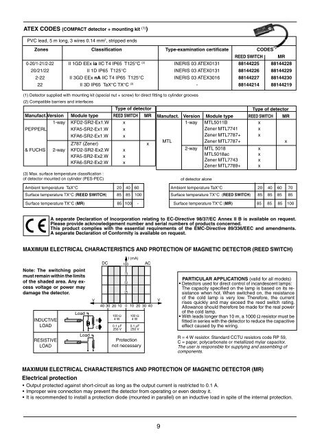
MAXIMUM ELECTRICAL CHARACTERISTICS AND PROTECTION OF MAGNETIC <strong>DE</strong>TECTOR (REED SWITCH)<br />
Note: The switching point<br />
must remain within the limits<br />
of the shaded area. Any excess<br />
voltage or power may<br />
damage the detector.<br />
Load<br />
Load<br />
DC<br />
l (mA)<br />
100 AC<br />
100 Ω<br />
4 W<br />
75<br />
50<br />
25<br />
V V<br />
R<br />
C<br />
40 30 20 10<br />
0,1 μF<br />
250 V<br />
0 10 20 30 40<br />
100 Ω<br />
4 W<br />
0,1 μF<br />
250 V<br />
Protection<br />
not necessary<br />
9<br />
Ambient temperature TaX°C 20 40 60 70<br />
Surface temperature TX°C (REED SWITCH) 85 85 85 85<br />
PARTICULAR APPLICATIONS (valid for all models)<br />
Detectors used for direct control of incandescent lamps:<br />
The capacity specifi ed on the lamp is based on its resistance<br />
when hot. When switched on, the resistance<br />
of the cold lamp is very low. Therefore, the current<br />
rises quickly and may exceed the reed switch rating.<br />
Allowance should therefore be made for the real power<br />
of the cold lamp.<br />
With leads longer than 10 m, a 1000 Ω resistor must be<br />
fi tted in series with the detector to reduce the capacitive<br />
effect caused by the wiring.<br />
R = 4 W resistor. Standard CCTU resistors code RP 59,<br />
C = paper, polycarbonate or metallized mylar capacitor.<br />
The user is responsible for supplying and assembling of<br />
components.<br />
MAXIMUM ELECTRICAL CHARACTERISTICS AND PROTECTION OF MAGNETIC <strong>DE</strong>TECTOR (MR)<br />
Electrical protection<br />
Output protected against short-circuit as long as the output current is restricted to 0.1 A.<br />
Improper wire connection may prevent the detector from operating or even destroy it.<br />
It is recommended to install a protection diode (mounted in parallel) on an inductive load in spite of the internal protection.


