
Create successful ePaper yourself
Turn your PDF publications into a flip-book with our unique Google optimized e-Paper software.
26<br />
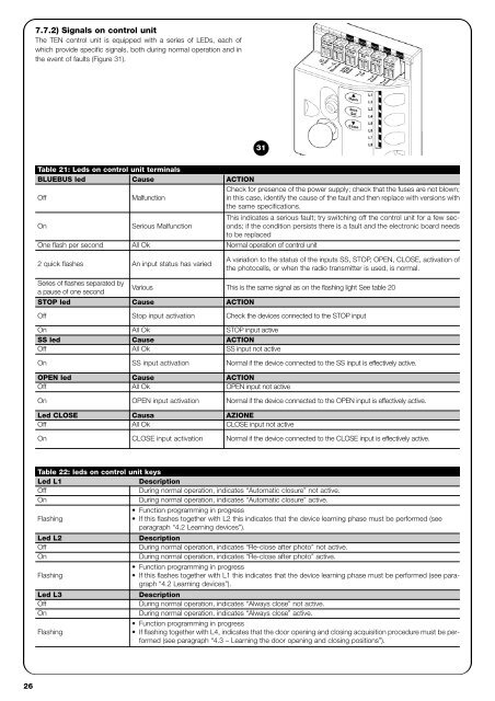
7.7.2) Signals on control unit<br />
The TEN control unit is equipped with a series of LEDs, each of<br />
which provide specific signals, both during normal operation and in<br />
the event of faults (Figure 31).<br />
Table 21: Leds on control unit terminals<br />
BLUEBUS led Cause ACTION<br />
Check for presence of the power supply; check that the fuses are not blown;<br />
Off<br />
Malfunction<br />
in this case, identify the cause of the fault and then replace with versions with<br />
the same specifications.<br />
On Serious Malfunction<br />
This indicates a serious fault; try switching off the control unit for a few seconds;<br />
if the condition persists there is a fault and the electronic board needs<br />
to be replaced<br />
One flash per second All Ok Normal operation of control unit<br />
2 quick flashes An input status has varied<br />
Series of flashes separated by<br />
a pause of one second<br />
STOP led Cause ACTION<br />
On All Ok STOP input active<br />
SS led Cause ACTION<br />
Off All Ok SS input not active<br />
OPEN led Cause ACTION<br />
Off All Ok OPEN input not active<br />
Led CLOSE Causa AZIONE<br />
Off All Ok CLOSE input not active<br />
31<br />
A variation to the status of the inputs SS, STOP, OPEN, CLOSE, activation of<br />
the photocells, or when the radio transmitter is used, is normal.<br />
Various This is the same signal as on the flashing light See table 20<br />
Off Stop input activation Check the devices connected to the STOP input<br />
On SS input activation Normal if the device connected to the SS input is effectively active.<br />
On OPEN input activation Normal if the device connected to the OPEN input is effectively active.<br />
On CLOSE input activation Normal if the device connected to the CLOSE input is effectively active.<br />
Table 22: leds on control unit keys<br />
Led L1 Description<br />
Off<br />
During normal operation, indicates “Automatic closure” not active.<br />
On<br />
During normal operation, indicates “Automatic closure” active.<br />
Function programming in progress<br />
Flashing<br />
If this flashes together with L2 this indicates that the device learning phase must be performed (see<br />
paragraph “4.2 Learning devices”).<br />
Led L2 Description<br />
Off During normal operation, indicates “Re-close after photo” not active.<br />
On<br />
During normal operation, indicates “Re-close after photo” active.<br />
Function programming in progress<br />
Flashing<br />
If this flashes together with L1 this indicates that the device learning phase must be performed (see paragraph<br />
“4.2 Learning devices”).<br />
Led L3 Description<br />
Off During normal operation, indicates “Always close” not active.<br />
On<br />
During normal operation, indicates “Always close” active.<br />
Flashing<br />
Function programming in progress<br />
If flashing together with L4, indicates that the door opening and closing acquisition procedure must be performed<br />
(see paragraph “4.3 – Learning the door opening and closing positions”).