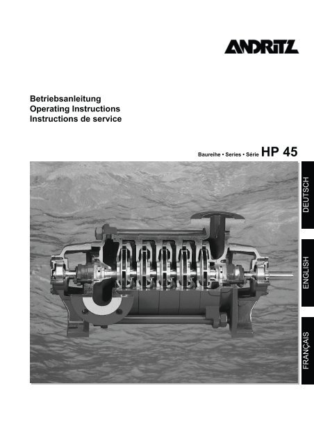
Betriebsanleitung Operating Instructions Instructions de ... - Andritz
Betriebsanleitung Operating Instructions Instructions de ... - Andritz
Betriebsanleitung Operating Instructions Instructions de ... - Andritz

You also want an ePaper? Increase the reach of your titles
YUMPU automatically turns print PDFs into web optimized ePapers that Google loves.
<strong>Betriebsanleitung</strong><br />
<strong>Operating</strong> <strong>Instructions</strong><br />
<strong>Instructions</strong> <strong>de</strong> service<br />
Baureihe • Series • Série HP 45<br />
FRANÇAIS<br />
ENGLISH<br />
DEUTSCH
Baureihe | Series | Série HP 45<br />
A. Hinweise zur neuen Benennung <strong>de</strong>r<br />
Baureihen<br />
• Um die Benennung <strong>de</strong>r Baureihen kun<strong>de</strong>nfreundlicher zu gestalten,<br />
wur<strong>de</strong>n diese vereinheitlicht und vereinfacht.<br />
• Zukünftig wer<strong>de</strong>n die Baureihen nach Produktgruppen benannt,<br />
welche jeweils für eine ein<strong>de</strong>utige Konstruktionsart<br />
steht. Die unterschiedlichen Produktgruppen können Sie <strong>de</strong>r<br />
Tabelle A entnehmen:<br />
ES<br />
ASC<br />
HP<br />
SU<br />
HDM<br />
SM<br />
SD<br />
SW<br />
Norm-/Blockpumpen<br />
Axial geteilte Spiralgehäusepumpen<br />
Hochdruckpumpen<br />
Unterwassermotorpumpen<br />
Doppelflutige Unterwassermotorpumpen<br />
Unterwassermotoren<br />
Trocken aufgestellte Abwasserpumpen<br />
Abwassertauchmotorpumpen<br />
Tabelle A: Übersicht <strong>de</strong>r neuen Produktgruppen<br />
• Die neue Benennung hat keinerlei Auswirkung auf die technische<br />
Ausführung <strong>de</strong>s Produkts.<br />
• Sofern im Dokument für die genaue I<strong>de</strong>ntifikation <strong>de</strong>s Produkts<br />
eine weitere Unterteilung erfor<strong>de</strong>rlich ist, wird diese mit<br />
Hilfe <strong>de</strong>r Design-Kennziffer angegeben. Diese zweistellige<br />
Ziffer können Sie <strong>de</strong>n Auftragspapieren entnehmen.<br />
• Die nachfolgen<strong>de</strong> Tabelle zeigt die bisherige und die neue<br />
Benennung <strong>de</strong>r in diesem Dokument enthaltenen Baureihen:<br />
Bisherige<br />
Benennung<br />
Neue<br />
Benennung<br />
45 32 HP 32-135<br />
45 40 HP 40-155<br />
45 50 HP 50-180<br />
45 65 HP 65-205<br />
Tabelle B: Bisherige und neue Benennung <strong>de</strong>r Baureihen<br />
A. Notes on the re-naming of Ritz<br />
product series<br />
• The names of our product series have been standardized and<br />
simplified to become more customer-friendly.<br />
• All series will now be named according to product groups,<br />
each of which stands for an explicit construction type. For the<br />
different product groups, please refer to Table A:<br />
ES<br />
ASC<br />
HP<br />
SU<br />
HDM<br />
SM<br />
SD<br />
SW<br />
End suction pumps<br />
Axial split case pumps<br />
High-pressure pumps<br />
Submersible motor pumps<br />
Double-suction submersible motor pumps<br />
Submersible motors<br />
Sewage dry pumps<br />
Sewage wet pumps<br />
Table A: Overview of the new product groups<br />
• The new names do not affect the technical product <strong>de</strong>sign.<br />
• If additional classification is required in the document for precise<br />
product i<strong>de</strong>ntification, the <strong>de</strong>sign co<strong>de</strong> will be stated. This<br />
two-digit figure is available in the or<strong>de</strong>r documents.<br />
• The following table shows the previous and the new names of<br />
the series inclu<strong>de</strong>d in this document:<br />
Previous<br />
name<br />
New<br />
name<br />
45 32 HP 32-135<br />
45 40 HP 40-155<br />
45 50 HP 50-180<br />
45 65 HP 65-205<br />
Table B: Previous and new series names<br />
A. Remarques à propos <strong>de</strong> la nouvelle dénomination<br />
<strong>de</strong>s séries<br />
• Afin <strong>de</strong> rendre les noms <strong>de</strong> séries plus conviviaux, nous<br />
avons décidé <strong>de</strong> les simplifier et <strong>de</strong> les uniformiser.<br />
• À l'avenir, les noms <strong>de</strong>s séries se rapporteront aux groupes<br />
<strong>de</strong> produits, lesquels reflèteront respectivement un type <strong>de</strong><br />
construction <strong>de</strong> manière explicite. Pour connaître les différents<br />
groupes <strong>de</strong> produits, se reporter au tableau A :<br />
ES<br />
ASC<br />
HP<br />
SU<br />
HDM<br />
SM<br />
SD<br />
SW<br />
Pompes normalisées/monoblocs<br />
Pompes à plan <strong>de</strong> joint axial<br />
Pompes haute pression<br />
Groupes électropompes immergés<br />
Groupes électropompes immergés à double flux<br />
Moteurs immergés<br />
Pompes à eaux usées installées à sec<br />
Groupes électropompes submersibles<br />
pur eaux usées<br />
Tableau A : aperçu <strong>de</strong>s nouveaux groupes <strong>de</strong> produits<br />
• Le changement <strong>de</strong> nom <strong>de</strong>s produits n'a aucune inci<strong>de</strong>nce<br />
sur la conception technique <strong>de</strong> ces <strong>de</strong>rniers.<br />
• Si une subdivision supplémentaire se révèle nécessaire dans<br />
le document pour une i<strong>de</strong>ntification plus précise du produit,<br />
cette <strong>de</strong>rnière sera indiquée via la référence du modèle. Ce<br />
nombre à <strong>de</strong>ux chiffres figure dans les documents <strong>de</strong> la comman<strong>de</strong>.<br />
• Le tableau suivant répertorie les anciennes et nouvelles dénominations<br />
<strong>de</strong>s séries mentionnées dans ce document :<br />
Ancienne<br />
dénomination<br />
Nouvelle<br />
dénomination<br />
45 32 HP 32-135<br />
45 40 HP 40-155<br />
45 50 HP 50-188<br />
45 65 HP 65-205<br />
Tableau B : anciennes et nouvelles dénominations <strong>de</strong>s séries<br />
2
Baureihe HP 45<br />
Inhaltsverzeichnis<br />
Seite<br />
1. Transport und Zwischenlagerung..........................................................................................4<br />
1.1 Transportieren...................................................................................................................................................................... 4<br />
1.2 Auspacken ........................................................................................................................................................................... 4<br />
1.3 Zwischenlagern.................................................................................................................................................................... 4<br />
1.4 Konservieren ........................................................................................................................................................................ 4<br />
2. Beschreibung...........................................................................................................................4<br />
2.1 Benennung........................................................................................................................................................................... 4<br />
2.2 Konstruktiver Aufbau............................................................................................................................................................ 4<br />
2.3 Bauformen A, E, S ............................................................................................................................................................... 4<br />
2.4 Abmessungen, Gewichte, Schwerpunkte, Fassungsvermögen........................................................................................... 5<br />
2.5 Angaben zum Einsatzort...................................................................................................................................................... 5<br />
3. Aufstellung/Einbau..................................................................................................................5<br />
3.1 Überprüfung vor Aufstellungsbeginn.................................................................................................................................... 5<br />
3.2 Aufstellung <strong>de</strong>r Komponenten eines Aggregates (A/Motormontage)................................................................................... 5<br />
3.3 Aufstellung <strong>de</strong>r komplett montierten Aggregate................................................................................................................... 5<br />
3.4 Rohrleitungen....................................................................................................................................................................... 7<br />
DEUTSCH<br />
4. Inbetriebnahme/Außerbetriebnahme.....................................................................................8<br />
4.1 Fertigmachen zum Betrieb ................................................................................................................................................... 8<br />
4.2 Einrichtungen zum Schutz von Personen ............................................................................................................................ 9<br />
4.3 Inbetriebnahme .................................................................................................................................................................... 9<br />
4.4 Außerbetriebnahme ............................................................................................................................................................. 9<br />
5. Wartung/Instandhaltung .........................................................................................................9<br />
5.1 Sicherheitshinweise ............................................................................................................................................................. 9<br />
5.2 Wartung und Inspektion ....................................................................................................................................................... 9<br />
5.3 Demontage- und Montagehinweise ................................................................................................................................... 10<br />
6. Störungen: Ursachen und Beseitigung...............................................................................11<br />
7. Anhang ...................................................................................................................................12<br />
7.1 Zulässiger Pumpenenddruck ............................................................................................................................................. 12<br />
7.2 Zulässige Stutzenbelastung............................................................................................................................................... 12<br />
7.3 Teileverzeichnis ................................................................................................................................................................. 13<br />
7.4 Schnittbil<strong>de</strong>r ....................................................................................................................................................................... 14<br />
3
Baureihe HP 45<br />
Beachten Sie ergänzend zu dieser <strong>Betriebsanleitung</strong> die<br />
separate <strong>Betriebsanleitung</strong> Sicherheitshinweise und die<br />
Motorbetriebsanleitung.<br />
1. Transport und Zwischenlagerung<br />
1.1 Transportieren<br />
• Gewicht und Schwerpunkt beachten.<br />
• Aggregat nicht an <strong>de</strong>n Aufhängeösen <strong>de</strong>s Motors<br />
befestigen.<br />
Beispiele für <strong>de</strong>n richtigen Transport von Pumpe, Motor und<br />
Aggregat:<br />
1.4 Konservieren<br />
Auf beson<strong>de</strong>re Bestellung konservieren wir Ihre Pumpe vor <strong>de</strong>r<br />
Auslieferung o<strong>de</strong>r vor Ort. Fragen Sie unseren Kun<strong>de</strong>ndienst.<br />
2. Beschreibung<br />
Hochdruckpumpen <strong>de</strong>r Baureihe HP sind mehrstufige, nicht<br />
selbstansaugen<strong>de</strong> Glie<strong>de</strong>r-Kreiselpumpen in einflutiger Bauart.<br />
Sie sind lieferbar in verschie<strong>de</strong>nen Bauformen und mit unterschiedlichen<br />
Lauf- und Leiträ<strong>de</strong>rn.<br />
Angaben zur gelieferten Ausführung entnehmen Sie bitte <strong>de</strong>r<br />
Vertragsdokumentation.<br />
2.1 Benennung<br />
HP 40-155.1/6/E + 30/2<br />
Baureihe<br />
Nennweite Druckstutzen [mm]<br />
Laufradnenndurchmesser [mm]<br />
Hydraulik-Kennziffer<br />
Stufenzahl<br />
Bauform<br />
Nennleistung P 2 [kW]<br />
Polzahl<br />
Beschreibung <strong>de</strong>r Bauformen siehe Punkt 2.3.<br />
Beispiel<br />
Darstellung für richtigen Transport<br />
2.2 Konstruktiver Aufbau<br />
Siehe auch Schnittbil<strong>de</strong>r (Punkt 7.4).<br />
2.2.1 Welle und Lager<br />
Die Welle ist durch Wellenschutzhülsen beidseitig vor Verschleiß<br />
geschützt. Welle und Lager sind für schweren Dauerbetrieb<br />
ausgelegt.<br />
2.2.2 Wellenabdichtung<br />
Falscher Transport<br />
1.2 Auspacken<br />
Lieferung auf Vollständigkeit und Unversehrtheit überprüfen.<br />
Lassen Sie festgestellte Mängel vom Transportunternehmen<br />
auf <strong>de</strong>m Orginal-Frachtbrief bestätigen und unterrichten Sie<br />
uns unverzüglich darüber.<br />
Angaben zur gelieferten Wellenabdichtung entnehmen Sie bitte<br />
<strong>de</strong>r Vertragsdokumentation.<br />
Bei För<strong>de</strong>rung gasen<strong>de</strong>r Medien: Stopfbuchspackung verwen<strong>de</strong>n.<br />
Bei Einsatz einer Gleitringdichtung muss eine permanente<br />
Entlüftung <strong>de</strong>s Gleitringdichtungsraumes gewährleistet sein.<br />
2.3 Bauformen A, E, S<br />
A<br />
E<br />
1.3 Zwischenlagern<br />
• Saug- und Druckanschlüsse mit Verschlusskappen, Blindflanschen<br />
o<strong>de</strong>r -stopfen verschließen.<br />
• Lagerraum: Staubfrei, trocken, gegen Hitze und Frost gesichert.<br />
• 14-tägig Pumpenläufer an <strong>de</strong>r Kupplung o<strong>de</strong>r Welle drehen.<br />
Die Lage <strong>de</strong>r Welle sollte zum vorhergehen<strong>de</strong>n Zustand eine<br />
Verän<strong>de</strong>rung erfahren.<br />
• Langzeitlagerung ab 3 Monaten: Konservierung notwendig!<br />
• Langzeitlagerung ab 2 Jahren: Schmierstoffe vor Inbetriebnahme<br />
<strong>de</strong>r Pumpe erneuern.<br />
4
Baureihe HP 45<br />
S<br />
3. Aufstellung/Einbau<br />
Eine sorgfältige und sachgerechte Aufstellung ist die Voraussetzung<br />
für einen störungsfreien Betrieb. Aufstellungsfehler<br />
können Personen- und Sachschä<strong>de</strong>n sowie<br />
einen vorzeitigen Verschleiß <strong>de</strong>r Pumpe verursachen.<br />
2.4 Abmessungen, Gewichte, Schwerpunkte,<br />
Fassungsvermögen<br />
Auf Anfrage.<br />
Gewicht: siehe Vertragsdokumentation.<br />
2.5 Angaben zum Einsatzort<br />
• Aggregat vor Witterungseinflüssen schützen.<br />
• Auf ausreichen<strong>de</strong> Be- und Entlüftung, Heizung, Kühlung sowie<br />
eventuelle Schallschutzvorschriften achten.<br />
• Überprüfen Sie, dass <strong>de</strong>r Transport/Abtransport <strong>de</strong>s Aggregates<br />
o<strong>de</strong>r <strong>de</strong>ssen Komponenten zum/vom Aufstellungsort<br />
ohne Unfallgefahr möglich ist. Vorhan<strong>de</strong>ne Türen o<strong>de</strong>r<br />
Durchbrüche müssen groß genug sein.<br />
• Notwendige Hebezeuge bzw. Vorrichtungen für <strong>de</strong>ren Anbringung<br />
müssen vorhan<strong>de</strong>n sein.<br />
2.5.1 Raumbedarf für Betrieb und Wartung<br />
• Freiräume für spätere Wartung von min<strong>de</strong>stens 2 Seiten vorsehen.<br />
Dieser Freiraum sollte Zwecks guter Zugänglichkeit<br />
min. 0,8m breit sein.<br />
• Aggregat sollte möglichst von allen Seiten zugänglich sein.<br />
• Lüfterhaube <strong>de</strong>s Motors benötigt ausreichen<strong>de</strong>n Abstand zu<br />
<strong>de</strong>n Wän<strong>de</strong>n. Achten Sie auf eine unbeeinträchtigte Luftzuund<br />
-abführung.<br />
2.5.2 Untergrund, Fundament<br />
• Betonfundamente sollen ausreichen<strong>de</strong> Festigkeit haben, um<br />
eine sichere, funktionsgerechte Aufstellung zu ermöglichen.<br />
• Länge <strong>de</strong>s Fundaments: Min<strong>de</strong>stens 100 mm länger als die<br />
Grundplatte.<br />
• Breite <strong>de</strong>s Fundaments: Die Befestigungsschrauben sollten<br />
min<strong>de</strong>stens 100 mm von <strong>de</strong>n Rän<strong>de</strong>rn <strong>de</strong>s Fundaments entfernt<br />
sein.<br />
• Höhe <strong>de</strong>s Fundaments: 20-30 mm Untermaß zum Unterlegen,<br />
Ausrichten und Ausgießen <strong>de</strong>r Grundplatte. Soll das<br />
Fundament mit Fliesen verklei<strong>de</strong>t wer<strong>de</strong>n, so ist das Untermaß<br />
um die Höhe von Estrich und Fliesen zu vergrößern.<br />
• Fundament möglichst bis auf ausreichend festen Untergrund<br />
in frostfreier Tiefe führen.<br />
• Fundamente, die auf einer Bauwerkssohle o<strong>de</strong>r Decke stehen,<br />
mit durchgehen<strong>de</strong>r Bewehrung an das tragen<strong>de</strong> Teil anschließen.<br />
• Zur Vermeidung von Resonanzschwingungen auf ausreichen<strong>de</strong><br />
Fundamentmasse achten.<br />
• Keine Gummi-, Kork-, Fe<strong>de</strong>r-, und/o<strong>de</strong>r Dämpfungselemente<br />
zwischen <strong>de</strong>r Grundplatte und <strong>de</strong>m Fundament anbringen.<br />
3.1 Überprüfung vor Aufstellungsbeginn<br />
Die Bauwerksgestaltung muss entsprechend <strong>de</strong>n Abmessungen<br />
<strong>de</strong>r Fundament- und Aufstellungspläne vorbereitet sein.<br />
3.2 Aufstellung <strong>de</strong>r Komponenten eines Aggregates (A/<br />
Motormontage)<br />
Siehe auch Punkt 3.3.<br />
• Aufbau von Pumpe und Motor auf einer gemeinsamen<br />
Grundplatte: Achsspiegel zwischen Pumpen- und Motorwelle<br />
angleichen.<br />
• Aufbau von Pumpe und Motor auf getrennten Fundamenten:<br />
Pumpe auf Fundament befestigen und ausrichten. Danach<br />
Motor auf Fundament befestigen und zur Pumpe<br />
ausrichten.<br />
3.3 Aufstellung <strong>de</strong>r komplett montierten Aggregate<br />
3.3.1 Horizontale Pumpen mit Antriebsmotoren auf<br />
einer Grundplatte montiert (E)<br />
• Fundamente o<strong>de</strong>r Aufstellungsflächen vor <strong>de</strong>m Aufsetzen<br />
<strong>de</strong>s Aggregates reinigen und Kalkmilch entfernen, um eine<br />
ausreichen<strong>de</strong> Verbindung zum Aufbeton (Ausgiesmasse) zu<br />
gewährleisten.<br />
• Muttern auf Befestigungsschrauben drehen. Befestigungsschrauben<br />
in die Befestigungsbohrungen <strong>de</strong>r Grundplatte<br />
einhängen.<br />
• Aggregat auf Fundament/Aufstellungsfläche setzen.<br />
• Grundplatte (1) mit Distanzblechen (2) unterlegen.<br />
(2)<br />
(3)<br />
(1)<br />
(6)<br />
(5)<br />
(4)<br />
Befestigungsschrauben<br />
DEUTSCH<br />
2.5.3 Versorgungsanschlüsse<br />
Überprüfen Sie, dass die für die Aufstellung bzw. <strong>de</strong>n späteren<br />
Betrieb nötigen Anschlüsse wie Strom, Wasser und Drainage in<br />
<strong>de</strong>r benötigten Form vorhan<strong>de</strong>n sind.<br />
5
Baureihe HP 45<br />
• Mit Maschinenwasserwaage (M) Ausrichtung <strong>de</strong>r Pumpe an<br />
<strong>de</strong>n Flanschen überprüfen. Die zulässige Abweichung darf<br />
max. 1 mm auf 1 m betragen.<br />
(M)<br />
Ausrichtungsfehler verursachen Lager- und Kupplungsschä<strong>de</strong>n,<br />
vorzeitigen Verschleiß <strong>de</strong>r Kupplungspakete und führen<br />
zu unruhigen Laufeigenschaften.<br />
3.3.2.1 Ausrichten mit Haarlineal<br />
(M)<br />
Ausrichten <strong>de</strong>r Pumpe an <strong>de</strong>n Flanschen<br />
• Bei Verwendung von Befestigungsschrauben (3), Aufnahmelöcher<br />
mit Beton (4) ausgießen. Beton dabei etwas über <strong>de</strong>m<br />
Aufnahmeloch anhäufen (siehe Bild Befestigungsschrauben).<br />
• Auf <strong>de</strong>n angehäuften, noch nicht abgebun<strong>de</strong>nen Beton links<br />
und rechts neben <strong>de</strong>n Befestigungsschrauben Stahlunterlagen<br />
(5) aufsetzen und ausrichten. Stahlunterlagen so anbringen,<br />
dass nur ein geringer Abstand zur Grundplatte (1)<br />
verbleibt.<br />
• Verbliebenen Zwischenraum nach <strong>de</strong>m Aushärten <strong>de</strong>s Betons<br />
mit planparallelen Blechen (6) in verschie<strong>de</strong>nen Dicken<br />
unterlegen.<br />
• Ausrichtungsunterlagen (2) entfernen.<br />
3.3.2 Ausrichten von elastischen Kupplungen (E)<br />
Die Wellen von Pumpe und Motor müssen nach <strong>de</strong>r Aufstellung<br />
grundsätzlich neu ausgerichtet wer<strong>de</strong>n. Die Kupplung ist <strong>de</strong>shalb<br />
vor <strong>de</strong>m Unter- / Ausgießen <strong>de</strong>r Grundplatte auszurichten:<br />
• Achshöhenunterschie<strong>de</strong> durch Unterlegen <strong>de</strong>r Grundplatte<br />
ausgleichen. Bei Grundplatten bis 1600 mm Länge: Nur im<br />
Bereich von Antriebsmaschine und/o<strong>de</strong>r Pumpe unterlegen.<br />
Bei größeren Grundplatten: Mehrfach unterlegen.<br />
Ausrichten mit Haarlineal<br />
• Haarlineal (1) parallel zur Pumpen- und Motorwelle über bei<strong>de</strong><br />
Kupplungshälften legen.<br />
• Abstän<strong>de</strong> a und b zwischen Lineal und Welle messen.<br />
• Bei gleichem Durchmesser von Pumpen- und Motorwelle:<br />
a=b.<br />
• Bei unterschiedlichem Durchmesser von Pumpen- und Motorwelle:<br />
a + 1/2A = b + 1/2B.<br />
• Vorgang an mehreren Stellen (ca. 90° versetzt) wie<strong>de</strong>rholen.<br />
Die Bedingungen für gleiche o<strong>de</strong>r unterschiedliche Wellendurchmesser<br />
müssen an allen Stellen erfüllt sein.<br />
• Abstand zwischen <strong>de</strong>n bei<strong>de</strong>n Kupplungshälften (Maß c) mit<br />
einer Lehre überprüfen. Für elastische Klauenkupplungen<br />
gelten folgen<strong>de</strong> Werte:<br />
Kupplungsgröße<br />
(Außendurchmesser)<br />
Abstand<br />
c<br />
80-140 mm 2-4 mm<br />
160-225 mm 2-6 mm<br />
250-400 mm 3-8 mm<br />
Tabelle 1: Abstand zwischen <strong>de</strong>n Kupplungshälften<br />
Der Abstand c muss an allen Stellen gleich sein.<br />
3.3.2.2 Ausrichten mit Messuhren<br />
Bei höheren Drehzahlen und/o<strong>de</strong>r Kupplungen mit Ausbaustück<br />
ist ein Ausrichten mit Messuhren erfor<strong>de</strong>rlich:<br />
Ausrichten<br />
• Kupplung mit Messuhren in radialer und axialer Richtung ausrichten.<br />
• Messuhren fest aufspannen. Messung an vier jeweils um 90°<br />
versetzten Messpunkten bei gleichzeitigem Drehen bei<strong>de</strong>r<br />
Kupplungshälften durchführen.<br />
Axialmessung<br />
• Differenzen durch Unterlegen von Blechen<br />
ausgleichen. Bleiben<strong>de</strong> Ungenauigkeit von<br />
0,03 mm, bezogen auf einen Messkreisdurchmesser<br />
von 200 mm, nicht überschreiten.<br />
Achshöhenunterschie<strong>de</strong> ausgleichen<br />
• Seitliche Verschiebungen zwischen Pumpe und Motor korrigieren:<br />
Fußschrauben <strong>de</strong>s Motors lösen, Motor zur Pumpe<br />
ausrichten, Fußschrauben anziehen.<br />
• Fundamentschrauben anziehen.<br />
Nach Anziehen <strong>de</strong>r Fundamentschrauben muss sich die Welle<br />
leicht und ohne Schwerpunkte drehen lassen (Ausführung mit<br />
Stopfbuchse: Bei nicht angezogener Stopfbuchspackung!).<br />
Radialmessung<br />
• Differenzen durch Verrücken bzw. durch Unterlegen<br />
entsprechen<strong>de</strong>r Bleche so ausgleichen,<br />
dass bleiben<strong>de</strong> Ungenauigkeit von<br />
0,03 mm nicht überschritten wird. Einstellen<br />
<strong>de</strong>r axialen Luft zwischen <strong>de</strong>n Kupplungshälften<br />
(Maß “c”) siehe Tabelle 1.<br />
6
Baureihe HP 45<br />
Kombinierte Axial- und Radialmessung<br />
• Eine im Aufbau relativ einfache Metho<strong>de</strong>, bei<strong>de</strong><br />
Messungen zu kombinieren. In die entsprechen<strong>de</strong>n<br />
Bohrungen <strong>de</strong>r angeschraubten o<strong>de</strong>r<br />
gespannten Flacheisenelemente wer<strong>de</strong>n die<br />
Messuhren eingelassen und durch z.B. Stiftschrauben<br />
fixiert.<br />
3.3.3 Vertikal stehen<strong>de</strong> Pumpen mit Scheibenkupplung<br />
und über eine Motortraglaterne aufgebautem<br />
Motor (S)<br />
Die Pumpen können je nach Größe <strong>de</strong>s Aggregates und örtlichen<br />
Gegebenheiten auf einem Betonfundament, auf tragen<strong>de</strong>m<br />
Betonbo<strong>de</strong>n o<strong>de</strong>r auf Profilträgern montiert wer<strong>de</strong>n.<br />
• Aggregat auf die Aufstellfläche setzen.<br />
• Pumpe ausrichten (siehe Punkt 3.3.1).<br />
• Pumpenfuß unterlegen.<br />
• Befestigungsschrauben mit Muttern in <strong>de</strong>n Pumpenfuß einführen<br />
und mit Beton ausgießen und abbin<strong>de</strong>n lassen.<br />
• Pumpenfuß mit nicht schwin<strong>de</strong>n<strong>de</strong>m Zementmörtel unterfüllen.<br />
Bei Lieferung <strong>de</strong>r Pumpe ohne aufgebautem Motor:<br />
• Abstand zwischen Motor- und Pumpenwelle ermitteln.<br />
• Motorseitige Kupplungshälfte auf die Motorwelle stecken. Die<br />
Kupplungshälfte verschieben, bis diese mit <strong>de</strong>r Hälfte <strong>de</strong>s<br />
oben ermittelten Abstan<strong>de</strong>s die Motorwelle überragt.<br />
• Die Motorwelle ist durch das Gewin<strong>de</strong>loch <strong>de</strong>r Kupplungshälfte<br />
anzubohren (Tiefe und Durchmesser <strong>de</strong>r Bohrung passend<br />
zum Zapfen <strong>de</strong>s Gewindstiftes).<br />
• Gewin<strong>de</strong>stift mit Zapfen einschrauben und gut anziehen.<br />
• Pumpenseitige Kupplungshälfte an Motorkupplung montieren<br />
und Schrauben anziehen (siehe Tabelle). Die Schrauben <strong>de</strong>r<br />
Scheibenkupplung sind durch kleben zu sichern.<br />
3.4.1 Allgemeines<br />
• Rohre unmittelbar vor und nach <strong>de</strong>r Pumpe abfangen und<br />
spannungsfrei an die Pumpe anschließen. Beachten Sie die<br />
maximal zulässigen Belastungen an Saug- und Druckflansch<br />
(siehe Punkt 7.2).<br />
• Nach Anschluss <strong>de</strong>r Rohrleitung: Pumpe auf Gängigkeit sowie<br />
Ausrichtung <strong>de</strong>r Kupplung überprüfen.<br />
• Kompensatoren mit Längenbegrenzung verwen<strong>de</strong>n.<br />
• Längenän<strong>de</strong>rung <strong>de</strong>r Rohrleitung durch Temperatureinflüsse<br />
und sonstige Belastungen, wenn nötig, durch Festpunkte vor<br />
und nach <strong>de</strong>r Pumpe abfangen.<br />
• Rohrleitungsführung: Kurz und direkt. Richtungsän<strong>de</strong>rungen<br />
möglichst vermei<strong>de</strong>n.<br />
3.4.2 Saugleitung<br />
Saugleitung<br />
• Max. Strömungsgeschwindigkeit: 2 m/s (bei zulässigem<br />
max. För<strong>de</strong>rstrom).<br />
• Keine Krümmer in verschie<strong>de</strong>nen Ebenen hintereinan<strong>de</strong>r anordnen.<br />
DEUTSCH<br />
Gewin<strong>de</strong> [mm]<br />
Anzugsmoment [Nm]<br />
M8 36<br />
M12 125<br />
M16 305<br />
Tabelle 2: Anzugsmomente für Kupplungsschrauben<br />
• Motor mit Kupplung auf Antriebslaterne aufbauen, Verbindungsschrauben<br />
anziehen.<br />
• Pumpenläufer axial auf Mitte einstellen.<br />
• Die Pumpenwelle ist durch das Gewin<strong>de</strong>loch <strong>de</strong>r Kupplungshälfte<br />
anzubohren (Tiefe und Durchmesser <strong>de</strong>r Bohrung passend<br />
zum Zapfen <strong>de</strong>s Gewindstiftes).<br />
• Gewin<strong>de</strong>stift mit Zapfen einschrauben und gut anziehen.<br />
3.3.4 Vergießen und sonstige Abschlussarbeiten<br />
• Nach Ausrichten und Befestigen <strong>de</strong>s Aggregates: Grundplatte(n)<br />
mit schnell abbin<strong>de</strong>n<strong>de</strong>m und nicht schwin<strong>de</strong>n<strong>de</strong>m Zement<br />
aus-/untergießen und verdichten.<br />
• Fundament min<strong>de</strong>stens 48 Stun<strong>de</strong>n abbin<strong>de</strong>n lassen.<br />
• Befestigungsschrauben nachziehen.<br />
• Ausrichtung von Pumpe und Motor überprüfen.<br />
3.4 Rohrleitungen<br />
Unverbindliche Empfehlungen für die richtige Auslegung und<br />
Verlegung von Rohrleitungen (die genaue Auslegung <strong>de</strong>r Rohrleitung<br />
ist Aufgabe <strong>de</strong>s Planers!).<br />
Hinweise zur Verlegung <strong>de</strong>r Saugleitung<br />
• Rohrleitung zu Pumpe hin ansteigend verlegen (min. 1%).<br />
• Rohrleitung muss absolut dicht und völlig entlüftet sein.<br />
• Für je<strong>de</strong> Pumpe separate Saugleitung vorsehen.<br />
• Bei Saugbetrieb ohne Fußventil: Vakuumanlage vorsehen.<br />
• In <strong>de</strong>r Saugleitung darf keine Möglichkeit einer Gasansammlung<br />
bestehen.<br />
7
Baureihe HP 45<br />
• Min<strong>de</strong>stüber<strong>de</strong>ckung (1):<br />
Hm = v²/2g+0,1<br />
Hm = Min<strong>de</strong>stüber<strong>de</strong>ckung<br />
v = Strömungsgeschwindigkeit bei max. För<strong>de</strong>rmenge<br />
g = Fallbeschleunigung = 9,81 m/s²<br />
• Der Abstand vom Behälterbo<strong>de</strong>n (2) muss min<strong>de</strong>stens <strong>de</strong>m<br />
halben Rohrleitungsdurchmesser entsprechen.<br />
3.4.3 Zulaufleitung<br />
Zulaufleitung<br />
• Auslegung wie Saugleitung, jedoch zur Pumpe hin stetig fallend<br />
verlegen (min. 1%).<br />
• Absperrschieber vor <strong>de</strong>r Pumpe vorsehen.<br />
3.4.4 Druckleitung<br />
• Rohrleitung stetig steigend verlegen.<br />
• Max. Strömungsgeschwindigkeit: 3 m/s (Verlusthöhe beachten).<br />
• Verengungen in <strong>de</strong>r Druckleitung vermei<strong>de</strong>n.<br />
• Rohrleitungssystem so verlegen, dass sich keine Feststoffe<br />
in einer an<strong>de</strong>ren Pumpe ablagern können.<br />
• Flanschausführung und Rohrleitung entsprechend <strong>de</strong>m max.<br />
möglichen Druck auslegen.<br />
• Gasansammlung vermei<strong>de</strong>n. Wenn erfor<strong>de</strong>rlich Hochpunkte<br />
entlüften.<br />
• Wechseln<strong>de</strong> Strömungsgeschwindigkeiten durch unterschiedliche<br />
Rohrleitungsdurchmesser vermei<strong>de</strong>n.<br />
• Rückflussverhin<strong>de</strong>rer und Absperrschieber einbauen.<br />
3.4.5 Druckproben<br />
• Einschlägige Vorschriften beachten.<br />
• Zulässige Nenndrücke <strong>de</strong>r einzelnen Komponenten berücksichtigen.<br />
• Bei Reihenschaltung ist die Überlagerung <strong>de</strong>r Pumpendrücke<br />
zu berücksichtigen.<br />
3.4.6 Rohrleitungsnebenanschlüsse<br />
Sperr- und Spülmedien:<br />
• Rohrleitungsverbindung und Anschlüsse herstellen.<br />
• Regulierventil und Magnetventil (stromlos geschlossen) einbauen.<br />
• Sperr- und Spüldruck muss min. 0,5 bar über <strong>de</strong>m max. Pumpenenddruck<br />
liegen.<br />
• Sperr- und Spülmenge über Regulierventil einstellen.<br />
Quenchmedien:<br />
• Drucklos in <strong>de</strong>n Quenchraum zuführen.<br />
• Bei Pumpen mit doppeltwirken<strong>de</strong>r Gleitringdichtung in Tan<strong>de</strong>m-Anordnung:<br />
Quenchbehälter ca. 1,5 m über <strong>de</strong>r Gleitringdichtung<br />
anordnen.<br />
4. Inbetriebnahme/Außerbetriebnahme<br />
4.1 Fertigmachen zum Betrieb<br />
Vor <strong>de</strong>m Einschalten <strong>de</strong>r Pumpe muss sichergestellt sein, dass<br />
nachstehen<strong>de</strong> Punkte geprüft und durchgeführt wur<strong>de</strong>n:<br />
• Bei horizontalen Pumpen mit elastischer Kupplung: Ausrichtung<br />
von Pumpe und Motor prüfen (siehe Punkt 3.3.2).<br />
• Befestigungsschrauben von Pumpe und Motor auf festen Sitz<br />
kontrollieren.<br />
• Funktionsgerechten Einbau <strong>de</strong>r Pumpe überprüfen.<br />
• Rückflussverhin<strong>de</strong>rer über <strong>de</strong>r Pumpe auf Dichtheit prüfen.<br />
4.1.1 Lagerung<br />
Siehe Punkt 5.2.1.<br />
4.1.2 Wellendichtung<br />
Beachten Sie eventuelle Son<strong>de</strong>rvorschriften (Schnittbild, Maßblatt,<br />
Anhang).<br />
4.1.2.1 Stopfbuchspackung<br />
• Evtl. lose mitgelieferte Stopfbuchspackung einsetzen.<br />
• Stopfbuchsbrille von Hand leicht und gleichmäßig anziehen.<br />
• Packung darf nicht an <strong>de</strong>r Welle kleben. Die Welle muss sich<br />
leicht drehen lassen.<br />
4.1.2.2 Gleitringdichtung<br />
Bei Pumpen mit einfachwirken<strong>de</strong>r Gleitringdichtung mit Quenchvorlage<br />
und Quenchbehälter:<br />
Quenchraum und Quenchbehälter auffüllen. Je nach För<strong>de</strong>rmedium<br />
sollte <strong>de</strong>r Quenchbehälter zu ca. 50% mit Wasser o<strong>de</strong>r<br />
einer an<strong>de</strong>ren Flüssigkeit gefüllt sein.<br />
4.1.3 Auffüllen/Entlüften<br />
• Druckschieber schließen, ggf. Zulaufschieber öffnen.<br />
• Pumpe mit För<strong>de</strong>rflüssigkeit füllen und völlig entlüften. Bei<br />
Saugbetrieb: Fülltrichter o<strong>de</strong>r Auffülleitung verwen<strong>de</strong>n.<br />
• Evtl. vorhan<strong>de</strong>ne Entlüftungsschrauben auf <strong>de</strong>r Saug-/Druckseite<br />
<strong>de</strong>s Spiralgehäuses öffnen, damit die Luft entweichen<br />
kann.<br />
• Bei gefüllter Druckleitung: Pumpe durch die Rückschlagklappe<br />
füllen (nur möglich bei Rückschlagklappen mit Umführung<br />
o<strong>de</strong>r Anlüfthebel).<br />
• Welle mehrmals drehen. Die Pumpe ist dann entlüftet,<br />
wenn nach <strong>de</strong>m Drehen <strong>de</strong>r Welle keine Luftblasen mehr<br />
aus <strong>de</strong>n Entlüftungsöffnungen austreten.<br />
• Nebenanschlüsse für Sperr- o<strong>de</strong>r Spülmedien mit Wasser<br />
auffüllen und blasenfrei entlüften. Verschluss- und Entlüftungsschrauben<br />
schließen.<br />
• Bei Pumpen mit Gleitringdichtung: Entlüftungsschrauben<br />
zur Entlüftung <strong>de</strong>s Dichtungsraumes (wenn vorhan<strong>de</strong>n) öffnen.<br />
Dichtungsraum mit Wasser auffüllen und blasenfrei entlüften.<br />
• Bei Pumpen mit Gleitringdichtung und Schnellentlüfter:<br />
Verschlusskappe <strong>de</strong>r Lufteintrittssperre vor Inbetriebnahme<br />
lockern (ca. 2 Umdrehungen). Kappe nicht ganz abschrauben,<br />
um eine Verschmutzung von außen zu verhin<strong>de</strong>rn.<br />
• Vor <strong>de</strong>m Einschalten <strong>de</strong>r Pumpe blasenfreie Entlüftung <strong>de</strong>s<br />
Dichtungsraumes überprüfen. Durch Trockenlauf kann die<br />
Gleitringdichtung beschädigt wer<strong>de</strong>n. Nach <strong>de</strong>r Überprüfung:<br />
Entlüftungsschrauben schließen.<br />
• Funktionsweise einer Gleitringdichtung: Zwei Gleitwerkstoffe<br />
gleiten gegeneinan<strong>de</strong>r und wer<strong>de</strong>n gleichzeitig von einem<br />
Flüssigkeitsfilm geschmiert. Bei einfachwirken<strong>de</strong>n<br />
Gleitringdichtungen wird dieser Film vom För<strong>de</strong>rmedium gebil<strong>de</strong>t.<br />
Eine Leckage in Abhängigkeit von Laufruhe, Druck,<br />
8
Baureihe HP 45<br />
Drehzahl und Wellendurchmesser <strong>de</strong>s Aggregates zwischen<br />
0,2 und 5 ml/h ist möglich (Gleitringdichtungen sind Verschleißteile<br />
auf die keine Gewährleistung übernommen wird).<br />
scha<strong>de</strong>t nicht, wenn sie am Anfang etwas stärker tropft.<br />
Durch das Aufquellen <strong>de</strong>r Stopfbuchspackung verringert sich<br />
die Leckage automatisch.<br />
4.1.4 Elektrische Anschlüsse<br />
Der elektrische Anschluss darf nur von einem qualifizierten<br />
Elektrofachmann in Übereinstimmung mit<br />
<strong>de</strong>n VDE- und EVU-Vorschriften durchgeführt wer<strong>de</strong>n.<br />
• Aggregat mit Motorschutzschalter ausrüsten.<br />
• Die vorhan<strong>de</strong>ne Netzspannung und Frequenz muss mit <strong>de</strong>n<br />
auf <strong>de</strong>m Leistungsschild angegebenen Daten übereinstimmen.<br />
• Brücken im Motorklemmkasten entsprechend <strong>de</strong>r gewünschten<br />
Schaltungsart kontrollieren bzw. neu anordnen.<br />
4.1.5 Drehrichtungskontrolle<br />
Drehrichtung muss mit <strong>de</strong>m Drehrichtungspfeil auf <strong>de</strong>r Pumpe<br />
übereinstimmen. Drehfeldmesser verwen<strong>de</strong>n. Ist kein Drehfeldmesser<br />
vorhan<strong>de</strong>n, so kann man behelfsmäßig bei aufgefüllter<br />
Pumpe o<strong>de</strong>r bei Trennung <strong>de</strong>s Antriebes von <strong>de</strong>r Pumpe<br />
<strong>de</strong>r Motor kurz ein- und sofort wie<strong>de</strong>r ausgeschaltet wer<strong>de</strong>n.<br />
Bei falscher Drehrichtung: Drehrichtung <strong>de</strong>s Motors vom Elektriker<br />
korrigieren lassen.<br />
Pumpe nicht entgegen ihrer angegebenen Betriebsrichtung betreiben<br />
(Richtungspfeil auf <strong>de</strong>m Gehäuse).<br />
4.2 Einrichtungen zum Schutz von Personen<br />
Pumpe nicht ohne Berührungsschutz für sich bewegen<strong>de</strong><br />
Teile (Kupplung) betreiben. Wur<strong>de</strong> die Pumpe<br />
ohne Berührungsschutz(e) ausgeliefert, so ist<br />
bzw. sind diese(r) vor <strong>de</strong>r Inbetriebnahme vom Betreiber<br />
anzubauen.<br />
Nicht mit <strong>de</strong>n Hän<strong>de</strong>n unter <strong>de</strong>n Berührungsschutz<br />
greifen.<br />
4.3 Inbetriebnahme<br />
4.3.1 Erstinbetriebnahme/Wie<strong>de</strong>rinbetriebnahme<br />
4.3.2 Funktionskontrolle<br />
• Überprüfen Sie, ob die Anzeigen von Manometer, Vakuummeter,<br />
Amperemeter, wenn vorhan<strong>de</strong>n auch Durchflussmesser<br />
mit <strong>de</strong>n Daten in <strong>de</strong>r Vertragsdokumentation<br />
übereinstimmen.<br />
• Überprüfen Sie die Betriebswerte bei allen Betriebszustän<strong>de</strong>n,<br />
die im System möglich sind (Parallelbetrieb von Pumpen,<br />
an<strong>de</strong>re För<strong>de</strong>rziele etc.).<br />
• Die ermittelten Werte als Richtwerte für die spätere Überwachung<br />
aufschreiben.<br />
• Temperatur <strong>de</strong>r Lager prüfen. Sie darf bis 50°C über <strong>de</strong>r Umgebungstemperatur<br />
liegen.<br />
4.3.3 Betrieb bei geschlossenem Schieber<br />
Pumpe niemals mit saug- und druckseitig geschlossenen<br />
Schiebern o<strong>de</strong>r bei saugseitig eingebautem<br />
Rückflussverhin<strong>de</strong>rer mit druckseitig geschlossenem<br />
Schieber betreiben. Das För<strong>de</strong>rmedium in <strong>de</strong>r<br />
Pumpe erwärmt sich bei dieser Betriebsweise in kurzer<br />
Zeit sehr stark und in <strong>de</strong>r Pumpe entsteht ein hoher<br />
Überdruck durch Dampfbildung. Bei<br />
Überschreitung <strong>de</strong>s Gehäuseberstdruckes können<br />
die Gehäuseteile explosionsartig bersten, was zu erheblichen<br />
Sach- und Personenschä<strong>de</strong>n führen<br />
kann.<br />
4.4 Außerbetriebnahme<br />
4.4.1 Abschalten<br />
• Absperrorgan in <strong>de</strong>r Druckleitung schließen.<br />
• Pumpe abschalten.<br />
• Ein Rückflussverhin<strong>de</strong>rer, über <strong>de</strong>m sich ein entsprechen<strong>de</strong>r<br />
Druck durch die Flüssigkeitssäule aufbaut, erübrigt in <strong>de</strong>r Regel<br />
die Betätigung einer druckseitigen Absperrung.<br />
• Zusatzanschlüsse schließen.<br />
4.4.2 Entleerung<br />
• Bei Frostgefahr: Pumpen und Rohrleitungen in Stillstandsperio<strong>de</strong>n<br />
entleeren bzw. gegen Einfrieren sichern.<br />
• Nach För<strong>de</strong>rung verschmutzter Medien sowie zur Vermeidung<br />
von Korrosion im Stillstand: Pumpe entleeren und gegebenenfalls<br />
spülen.<br />
DEUTSCH<br />
• Pumpe nur mit Flüssigkeitsfüllung und Gegendruck anfahren.<br />
• Sperr- und Spülanschlüsse öffnen.<br />
• Bei nicht gefüllter Druckleitung:<br />
- Druckschieber völlig schließen und wie<strong>de</strong>r einige Umdrehungen<br />
öffnen.<br />
- Danach Pumpe einschalten.<br />
- Nach Erreichen <strong>de</strong>r Betriebsdrehzahl Schieber unter Beobachtung<br />
von Manometer und Amperemeter etwas öffnen<br />
und warten, bis die Leitung ganz gefüllt ist. Dabei<br />
Absperrarmatur langsam und nicht zu weit öffnen.<br />
- Nach Auffüllen und Entlüften <strong>de</strong>s Systems ist <strong>de</strong>r Betriebspunkt<br />
zu überprüfen. Das Aggregat darf nur innerhalb<br />
<strong>de</strong>r zugesicherten Leistungsdaten betrieben wer<strong>de</strong>n.<br />
Es empfiehlt sich die Betriebsdaten <strong>de</strong>r Erstinbetriebsetzung<br />
in einem Protokoll festzuhalten.<br />
• Bei Pumpen mit Stopfbuchspackung: Stopfbuchse bei laufen<strong>de</strong>r<br />
Pumpe vorsichtig nachziehen. Die Stopfbuchspakkung<br />
darf sich nicht erwärmen und soll immer tropfen. Es<br />
5. Wartung/Instandhaltung<br />
5.1 Sicherheitshinweise<br />
• Arbeiten an <strong>de</strong>r Maschine sind grundsätzlich nur<br />
bei abgeklemmten elektrischen Anschlüssen<br />
durchzuführen. Das Pumpenaggregat ist vor ungewolltem<br />
Einschalten zu sichern.<br />
• Bei Montage/Demontage o<strong>de</strong>r Nachstellarbeiten<br />
an <strong>de</strong>r Stopfbuchsbrille: Sicherheitshandschuhe<br />
zum Schutz vor scharfen Kanten verwen<strong>de</strong>n.<br />
5.2 Wartung und Inspektion<br />
5.2.1 Betriebsstoffe: Füllmengen und Schmierfristen<br />
5.2.1.1 Pumpe mit fettgeschmierten Lagern zur<br />
Nachschmierung durch Fettschmiernippel<br />
(Normalausführung)<br />
Die Pumpen sind werksseitig mit Fettfüllung versehen.<br />
• Nachschmierung: min<strong>de</strong>stens halbjährlich.<br />
9
Baureihe HP 45<br />
• Fettmenge: 20 bis 30 g je Schmierstelle.<br />
• Fettqualität: Lithium verseiftes Fett nach DIN 51825, alterungsbeständig,<br />
säurefrei, korrosionsbeständig, wasserabweisend,<br />
Gebrauchstemperatur -30 bis 130°C,<br />
Penetrationszahl 2 bis 3, Walkpenetration 265 bis 295, Tropfpunkt<br />
ca. 190°C.<br />
• Empfohlene han<strong>de</strong>lsübliche Fette:<br />
- UNIREX N2, Fa. ESSO<br />
- OPTIMOL OLISTA LONGTIME o<strong>de</strong>r OLIT 2, Fa. OPTI-<br />
MOL<br />
- GLISSANTO 20, Fa. DEA<br />
- ENERGREASE MSLS-EP2, Fa. BP<br />
• Überfettung <strong>de</strong>r Lager vermei<strong>de</strong>n. Durch Überfettung kommt<br />
es zu Überhitzungsschä<strong>de</strong>n.<br />
• Nach mehrmaligem Nachfetten o<strong>de</strong>r Erwärmung von mehr<br />
als 50°C über Raumtemperatur: Lager<strong>de</strong>ckel öffnen und<br />
überschüssiges bzw. verbrauchtes Fett entfernen.<br />
• Nach einem Lageraustausch: Lager zur Hälfte mit Fett füllen.<br />
5.2.1.2 Pumpe mit lebensdauerfettgeschmierten<br />
Lagern (Son<strong>de</strong>rausführung)<br />
Die Pumpen sind werksseitig mit lebensdauerfettgeschmierten<br />
Lagern versehen. Die Fettfüllung reicht für ca. 15.000 Betriebsstun<strong>de</strong>n<br />
bzw. 2 Jahre. Bei ungünstigen Betriebsbedingungen,<br />
z.B. hohe Außentemperatur, Feuchtigkeit o<strong>de</strong>r Erwärmung sind<br />
die Lager früher zu überprüfen und wenn notwendig auszuwechseln.<br />
Intervalle richten sich nach <strong>de</strong>n För<strong>de</strong>rmedien und müssen<br />
anfangs, bis Erkenntnisse über <strong>de</strong>n Verschleißfortschritt vorliegen,<br />
häufiger erfolgen.<br />
5.3 Demontage- und Montagehinweise<br />
5.3.1 Montage <strong>de</strong>r Stufengehäuse<br />
Die erfor<strong>de</strong>rlichen Anzugsmomente <strong>de</strong>r Zuganker sind zu beachten:<br />
Typ<br />
Demontage und Montage sind unter Beachtung <strong>de</strong>r<br />
Schnittzeichnung (siehe Punkt 7.4) nur von qualifiziertem<br />
Fachpersonal vorzunehmen. Die Reihenfolge <strong>de</strong>r Demontage<br />
ist aus <strong>de</strong>r Schnittzeichnung abzuleiten.<br />
• Bei Demontage <strong>de</strong>s Pumpengehäuses: Pumpengehäuse<br />
und Rohrleitung gegen Umstürzen sichern.<br />
Anzugsmoment<br />
[Nm]<br />
Anzahl<br />
Zuganker<br />
Gewin<strong>de</strong><br />
[mm]<br />
HP 32-135 143,2 4 M 20<br />
HP 40-155 239,1 4 M 24<br />
HP 50-180 315,1 4 M 24<br />
HP 65-205 464,7 4 M 27<br />
Tabelle 3: Anzugsmomente <strong>de</strong>r Zuganker<br />
5.2.2 Überwachung <strong>de</strong>r Pumpe während <strong>de</strong>s Betriebes<br />
Für die Betriebsüberwachung sind folgen<strong>de</strong> Punkte regelmäßig<br />
zu beachten:<br />
• Ruhigen Lauf <strong>de</strong>r Pumpe überwachen. Treten ungewöhnlich<br />
starke Vibrationen auf, Aggregat sofort abschalten und die<br />
Ursache ermitteln (Laufradscha<strong>de</strong>n, Fremdkörper, Verstopfung<br />
etc.).<br />
• Bei Pumpen mit Stopfbuchspackung: Leckage <strong>de</strong>r Wellenabdichtung<br />
überprüfen (Leckwasser ca. 5-10 l/h). Bei<br />
Stopfbuchspackungen mit Sperrwasserbeaufschlagungen:<br />
Sperrwasserbedarf überprüfen:<br />
Sperrwasserbedarf<br />
Nennweite Druckstutzen<br />
[m³/h] bei Δp 0,5 bar<br />
32 - 65 0,10<br />
Tabelle 2: Sperrwasserbedarf<br />
• Bei Pumpen mit Gleitringdichtung: Bei Flüssigkeitsaustritt<br />
an <strong>de</strong>r Welle, Gleitringdichtung reinigen und überprüfen,<br />
wenn notwendig auswechseln. Eine Leckage in Abhängigkeit<br />
von Laufruhe, Druck, Drehzahl und Wellendurchmesser <strong>de</strong>s<br />
Aggregates zwischen 0,2 und 5 ml/h ist möglich (Gleitringdichtungen<br />
sind Verschleißteile auf die keine Gewährleistung<br />
übernommen wird).<br />
• Örtliche Anzeigen regelmäßig, am besten arbeitstäglich ablesen<br />
und bei großen Abweichungen unmittelbar reagieren.<br />
• In vorgegebenen Abstän<strong>de</strong>n, am besten wöchentlich einmal,<br />
alle gemessenen und registrierten Betriebswerte überprüfen<br />
und in einem Aggregatebuch notieren. Über <strong>de</strong>n Trend (Datenentwicklung)<br />
ist <strong>de</strong>r Wartungszyklus festlegen.<br />
• Manometer mit Drei-Wege-Manometerhahn: Zur Ablesung<br />
Manometerhahn öffnen und anschließend sofort wie<strong>de</strong>r<br />
schließen.<br />
• Bei stark korrosiven/abrasiven För<strong>de</strong>rmedien: Druckführen<strong>de</strong><br />
Bauteile regelmäßig überprüfen, um Verschleiß rechtzeitig<br />
- vor Eintritt eines Scha<strong>de</strong>ns - zu erkennen. Die<br />
10
Baureihe HP 45<br />
6. Störungen: Ursachen und Beseitigung<br />
1) Pumpe för<strong>de</strong>rt nicht, För<strong>de</strong>rstrom zu klein<br />
2) För<strong>de</strong>rstrom zu groß<br />
3) Motor überlastet, Temperaturwächter schaltet ab<br />
4) Druckstoß im System<br />
5) Wie<strong>de</strong>rholte mechanische Schä<strong>de</strong>n nach kurzer Zeitspanne<br />
1) 2) 3) 4) 5) Störungsursache Beseitigung<br />
Zu starke Wasserspiegelabsenkung (zu<br />
große Saughöhe, zu kleine Zulaufhöhe)<br />
Pumpe nicht vollständig entlüftet<br />
Saugleitung nicht völlig entlüftet<br />
Pumpe för<strong>de</strong>rt gegen zu hohen Druck<br />
Pumpe för<strong>de</strong>rt gegen zu kleinen Druck<br />
Falsche Drehrichtung<br />
Zulaufleitung, Armaturen o<strong>de</strong>r Pumpe<br />
verstopft<br />
Verschleiß <strong>de</strong>r Innenteile<br />
Zu geringe Drehzahl<br />
Zu hohe Drehzahl<br />
Lauf auf 2 Phasen<br />
Aggregat nicht genau ausgerichtet<br />
Stopfbuchspackung zu fest angezogen<br />
Zu hohe Dichte <strong>de</strong>s För<strong>de</strong>rmediums<br />
Rohrleitungsführung<br />
Systemfehler<br />
• Versorgung und Dimensionierung <strong>de</strong>s Systems überprüfen<br />
• Niveausteuerung überprüfen<br />
• Pumpe entlüften<br />
• Wellendichtung auf Dichtheit überprüfen<br />
• Saugleitung entlüften<br />
• Saugleitung und Armaturen auf Dichtheit überprüfen<br />
• Absperrorgane weiter öffnen<br />
• Dimensionierung <strong>de</strong>r Anlage überprüfen<br />
(zu hohe Druckverluste?)<br />
• För<strong>de</strong>rhöhe <strong>de</strong>r Pumpe anpassen<br />
(nur nach Rücksprache mit <strong>de</strong>m Hersteller)<br />
• Dimensionierung <strong>de</strong>s Systems überprüfen<br />
• Druckseitigen Absperrschieber weiter drosseln<br />
• Drehrichtung korrigieren<br />
• Ablagerungen entfernen<br />
• Verschleißteile erneuern<br />
• Elektrische Installation überprüfen<br />
• Elektrische Installation überprüfen<br />
• Elektrische Installation überprüfen<br />
• Ausrichtung korrigieren<br />
• Spannungsfreien Anschluss <strong>de</strong>r Rohrleitung an die Pumpe<br />
überprüfen. Verspannungen beseitigen<br />
• Stopfbuchspackung weiter lösen<br />
• Stärkeren Motor verwen<strong>de</strong>n<br />
(nur nach Rücksprache mit <strong>de</strong>m Hersteller)<br />
• System überprüfen, Ursache beseitigen<br />
• Ursachenanalyse nach Inspektion<br />
Tabelle 4: Störungen<br />
DEUTSCH<br />
11
Baureihe HP 45<br />
7. Anhang<br />
7.1 Zulässiger Pumpenenddruck<br />
Dichtungsart<br />
max. Arbeitstemperatur<br />
Max zulässiger Pumpen<strong>de</strong>nddruck* [bar]<br />
Gehäuseteile aus<br />
EN-GJL-250 CuSn10-C 1.4408<br />
Weichpackungs-Stopfbuchse -20°C bis +110°C 40 35 40<br />
Gleitringdichtung unentlastet (Chromguss/Kohle) -20°C bis +120°C 12 12 12<br />
Gleitringdichtung unentlastet (SIC/SIC) -20°C bis +80°C 12 12 12<br />
Gleitringdichtung entlastet (SIC/Kohle) -20°C bis +140°C 40 35 40<br />
Gleitringdichtung entlastet (SIC/SIC) -20°C bis +80°C 40 35 40<br />
Tabelle 5: Pumpenenddruck<br />
* Der maximal zulässige Pumpen-Enddruck [bar] setzt sich zusammen aus <strong>de</strong>m Zulaufdruck und <strong>de</strong>r Pumpen-För<strong>de</strong>rhöhe im<br />
Mengen-Nullpunkt.<br />
7.2 Zulässige Stutzenbelastung<br />
• Bezogen auf Aufstellungsart E<br />
Stutzen vertikal<br />
Stutzen horizontal<br />
Nennweite<br />
32 40 50 65<br />
[mm]<br />
Fx 340 450 600 700<br />
Kräfte<br />
[N]<br />
Momente<br />
[Nm]<br />
Kräfte<br />
[aN]<br />
Momente<br />
[Nm]<br />
Fy 400 500 650 800<br />
Fz 300 400 580 650<br />
ΣF 600 800 1050 1250<br />
Mx 320 350 400 450<br />
My 190 200 250 250<br />
Mz 240 250 300 300<br />
ΣM 440 450 550 600<br />
Fx 400 500 650 800<br />
Fy 300 400 550 650<br />
Fz 340 450 600 700<br />
ΣF 600 800 1050 1250<br />
Mx 320 350 400 450<br />
My 190 200 250 250<br />
Mz 240 250 300 300<br />
ΣM 440 450 550 600<br />
Tabelle 6: Maximal zulässige Stutzenbelastung<br />
F Y<br />
F Y<br />
M Y<br />
F Z<br />
F X<br />
M Z<br />
F Z<br />
M X FX<br />
Skizze zur Stutzenbelastung<br />
12
Baureihe HP 45<br />
7.3 Teileverzeichnis<br />
VDMA-Nr. Benennung VDMA-Nr. Benennung<br />
106 Sauggehäuse 471.2 Dichtungs<strong>de</strong>ckel<br />
107 Druckgehäuse 507 Spritzring<br />
108 Stufengehäuse 524.1 Wellenschutzhülse<br />
173 Deckwand 524.2 Wellenschutzhülse<br />
174.1 Leitschaufeleinsatz 524.3 Wellenschutzhülse<br />
174.2 Leitschaufeleinsatz 524.4 Wellenschutzhülse<br />
181 Pumpenstän<strong>de</strong>r 524.5 Wellenschutzhülse<br />
210.1 Welle 525 Abstandshülse<br />
210.2 Welle 545 Lagerbuchse<br />
230 Laufrad 550 Stützscheibe<br />
321 Rillenkugellager 703 Sperrleitung<br />
332 Lagerstuhl 861.1 Kupplungshälfte<br />
341 Antriebslaterne 861.2 Kupplungshälfte<br />
360.1 Lager<strong>de</strong>ckel 902 Stiftschraube<br />
360.2 Lager<strong>de</strong>ckel 903.1 Verschlussschraube<br />
381 Lagereinsatz 903.2 Verschlussschraube<br />
400.1 Flachdichtung 904.1 Gewin<strong>de</strong>stift mit Zapfen<br />
400.2 Flachdichtung 904.2 Gewin<strong>de</strong>stift mit Zapfen<br />
412.1 Runddichtring 905 Verbindungsschraube<br />
412.2 Runddichtring 920.1 Sechskantmutter<br />
433.1 Gleitringdichtung, unentlastet 920.2 Sechskantmutter<br />
433.2 Gleitringdichtung, entlastet 932.1 Seeger-Außensicherung<br />
452 Stopfbuchsbrille 932.2 Seeger-Außensicherung<br />
459 Sperringbuchse 940.1 Passfe<strong>de</strong>r<br />
461 Stopfbuchspackung 940.2 Passfe<strong>de</strong>r<br />
471.1 Dichtungs<strong>de</strong>ckel 940.3 Passfe<strong>de</strong>r<br />
DEUTSCH<br />
13
Baureihe HP 45<br />
7.4 Schnittbil<strong>de</strong>r<br />
7.4.1 Bauform A<br />
932.1 332 412.1 524.2 173 106 703 230 108 107 459 461 452 332 321 940.1<br />
903.1 524.1 940.3<br />
174.1 174.2 903.1<br />
321<br />
360.1<br />
920.1<br />
524.2<br />
550 902 903.2 940.2 412.2 905 903.2 920.2 412.1 507 360.2 210.1<br />
7.4.2 Bauform S<br />
7.4.3 Son<strong>de</strong>rausführung Gleitringdichtung<br />
341<br />
550<br />
452<br />
903.1<br />
940.3<br />
174.2<br />
107<br />
174.1<br />
703<br />
108<br />
904.1<br />
861.1<br />
861.2<br />
904.2<br />
940.1<br />
932.1<br />
920.1<br />
902<br />
412.1<br />
524.2<br />
461<br />
920.2<br />
459<br />
905<br />
230<br />
412.2<br />
Gleitringdichtung unentlastet<br />
471.1<br />
400.2<br />
433.1<br />
932.1<br />
550 412.1 525 932.2 524.3<br />
Gleitringdichtung entlastet<br />
940.2<br />
106<br />
524.1<br />
210.2<br />
903.1<br />
471.2<br />
181<br />
173<br />
903.2<br />
932.1<br />
545<br />
381<br />
400.1<br />
471.1<br />
400.2<br />
433.2<br />
932.1<br />
524.3 412.1 524.4<br />
14
Series HP 45<br />
In<strong>de</strong>x<br />
Page<br />
1. Handling and intermediate storage .....................................................................................16<br />
1.1 Handling............................................................................................................................................................................. 16<br />
1.2 Unpacking .......................................................................................................................................................................... 16<br />
1.3 Intermediate storage .......................................................................................................................................................... 16<br />
1.4 Preservation....................................................................................................................................................................... 16<br />
2. Description.............................................................................................................................16<br />
2.1 Designation ........................................................................................................................................................................ 16<br />
2.2 Construction....................................................................................................................................................................... 16<br />
2.3 Mounting arrangements A, E, S......................................................................................................................................... 16<br />
2.4 Dimensions, weights, centres of gravity, capacity.............................................................................................................. 17<br />
2.5 Installation requirements.................................................................................................................................................... 17<br />
3. Mounting/installation ............................................................................................................17<br />
3.1 Preliminary checks ............................................................................................................................................................. 17<br />
3.2 Mounting of pump and motor (arrangement A).................................................................................................................. 17<br />
3.3 Installation of assembled pump sets .................................................................................................................................. 17<br />
3.4 Piping ................................................................................................................................................................................. 19<br />
4. Commissioning and shut-down...........................................................................................20<br />
4.1 Commissioning................................................................................................................................................................... 20<br />
4.2 Safety precautions ............................................................................................................................................................. 20<br />
4.3 Start-up .............................................................................................................................................................................. 21<br />
4.4 Shut-down.......................................................................................................................................................................... 21<br />
5. Maintenance/servicing..........................................................................................................21<br />
ENGLISH<br />
5.1 Safety Notices.................................................................................................................................................................... 21<br />
5.2 Maintenance and inspection .............................................................................................................................................. 21<br />
5.3 Disassembly and assembly instructions ............................................................................................................................ 22<br />
6. Problems: Causes and Remedies........................................................................................23<br />
7. Appendix ................................................................................................................................23<br />
7.1 Permissible pump pressure................................................................................................................................................ 23<br />
7.2 Permissible branch loads................................................................................................................................................... 24<br />
7.3 Parts list ............................................................................................................................................................................. 25<br />
7.4 Sectional drawings............................................................................................................................................................. 26<br />
15
Series HP 45<br />
These instructions must be read in conjunction with the<br />
separate User’s Safety Manual and the Motor <strong>Operating</strong> <strong>Instructions</strong>.<br />
1. Handling and intermediate storage<br />
1.1 Handling<br />
• Always take the weight and centre of gravity into<br />
consi<strong>de</strong>ration.<br />
• Never use the motor eye bolts when slinging assembled<br />
pump sets.<br />
Examples of correctly handling the pump, motor and set:<br />
2. Description<br />
High pressure pumps of the type HP are non self priming, multistage<br />
ring section pumps in a single flow construction. They are<br />
available in various mounting arrangements and with different<br />
impellers.<br />
Please see the contractual documents for <strong>de</strong>tails of the supplied<br />
<strong>de</strong>sign.<br />
2.1 Designation<br />
Series<br />
HP 40-155.1/6/E + 30/2<br />
Nominal branch diameter [mm]<br />
Nominal impeller diameter [mm]<br />
Hydraulics ID<br />
Number of stages<br />
Mounting arrangement<br />
Nominal capacity P 2 [kW]<br />
Number of poles<br />
Example<br />
For a <strong>de</strong>scription of mounting arrangements, see paragraph<br />
2.3.<br />
2.2 Construction<br />
Please refer also to the sectional drawings in paragraph 7.4.<br />
Proper handling<br />
2.2.1 Shaft and bearings<br />
The shaft is protected against wear by shaft protection sleeves<br />
on both si<strong>de</strong>s. Shaft and bearings are rated for continuous,<br />
heavy-duty operation.<br />
2.2.2 Shaft sealing<br />
Improper handling<br />
1.2 Unpacking<br />
Check that the <strong>de</strong>livery is complete and undamaged. Any missing<br />
parts or damage must be confirmed by the carrier on the<br />
original freight note and reported to us immediately.<br />
The fitted shaft sealing arrangements are <strong>de</strong>scribed in <strong>de</strong>tail in<br />
the contract documentation.<br />
Packed gland must be used when pumping gaseous media. If<br />
a mechanical seal is used, make sure that the seal housing is<br />
permanently vented.<br />
2.3 Mounting arrangements A, E, S<br />
A<br />
E<br />
1.3 Intermediate storage<br />
• Seal the suction and <strong>de</strong>livery branches, using closure caps,<br />
plugs or blank flanges.<br />
• Store in dry, dust free conditions protected from frost or excessive<br />
heat.<br />
• Turn the rotating assembly on the shaft or coupling a few<br />
times every 2 weeks and leave in a different angular position.<br />
• Long-term storage (over 3 month) preservation required.<br />
• Long-term storage (over 2 years) renew the lubricants before<br />
installing the pump.<br />
1.4 Preservation<br />
If requested, we will preserve your pumps before <strong>de</strong>livery or at<br />
site. Please contact our service <strong>de</strong>partment.<br />
16
Series HP 45<br />
S<br />
Care and attention to <strong>de</strong>tail during installation are essential<br />
for a trouble-free operation. Incorrect procedures during<br />
installation may create hazards for personnel or<br />
property or lead to premature failure of the pump.<br />
3.1 Preliminary checks<br />
Check that the dimensions of the plinth/foundation are in accordance<br />
with the drawings.<br />
2.4 Dimensions, weights, centres of gravity, capacity<br />
Information on request.<br />
For weights refer to the contract documentation.<br />
2.5 Installation requirements<br />
• Protect motors and pumps from the weather.<br />
• Ensure that the workplace is a<strong>de</strong>quately ventilated/heated/<br />
cooled and observe noise protection requirements.<br />
• Check that the transport / taking away of the pump set or its<br />
components to / from installation site is possible without danger<br />
of acci<strong>de</strong>nt.<br />
Openings must be large enough.<br />
• A<strong>de</strong>quately rated lifting equipment must be available.<br />
3.2 Mounting of pump and motor (arrangement A)<br />
See also para. 3.3.<br />
• Common baseplate mounted pump and motor: Adjust the axial<br />
clearance between pump and motor shaft ends.<br />
• Separately mounted pump and motor: Secure the pump onto<br />
the plinth and align it. Then secure the motor and align it with<br />
the pump.<br />
3.3 Installation of assembled pump sets<br />
3.3.1 Horizontal pumps with base plate-mounted drive<br />
motors (E)<br />
• Before lowering the set into position clean the plinth surface<br />
and remove any limewash to ensure sound bonding.<br />
• Hang the fixing bolts with nuts in the baseplate fixing holes.<br />
• Lower the set into position on the plinth surface.<br />
• Place spacer sheets (2) un<strong>de</strong>rneath the baseplate (1).<br />
(3)<br />
2.5.1 Space required for operation and maintenance<br />
• Ensure that sufficient space, at least from 2 si<strong>de</strong>s, is left for<br />
subsequent maintenance requirements. This space should<br />
have, for reason of good accessibility, min. 0.8 m width.<br />
• The set should be easily accessible from all si<strong>de</strong>s.<br />
• The motor cooling fan requires a<strong>de</strong>quate clearance around<br />
the cowl. Ensure that the air inlet and outlet areas are unobstructed.<br />
(2)<br />
(1)<br />
(6)<br />
(5)<br />
(4)<br />
2.5.2 Foundations<br />
• Concrete plinths must be a<strong>de</strong>quately supported in or<strong>de</strong>r to<br />
ensure installation safe and functional.<br />
• Length: At least 100 mm longer than the baseplate.<br />
• Width: The fixing bolts should be at least 100 mm in front of<br />
the edge of the foundation.<br />
• Height: 20-30 mm un<strong>de</strong>rsize to un<strong>de</strong>rlay, adjust and grout<br />
the baseplate. If the plinth is to be tiled, make an additional allowance<br />
consi<strong>de</strong>ring the height of the plaster and the tiles.<br />
• The <strong>de</strong>pth of the foundation should be sufficient to prevent<br />
frost and to be on firm ground.<br />
• Plinths which rest on a structural floor or ceiling should be integrated<br />
into the original construction using bridging reinforcement.<br />
• Foundations should contain sufficient mass in or<strong>de</strong>r to dampen<br />
resonant vibrations.<br />
• Do not place rubber, cork, feather and/or resilient mats between<br />
baseplate and plinth.<br />
Fixing bolts<br />
• Check the alignment of pumps on the flange machined surfaces<br />
using a spirit level. A margin of error of 1 mm in 1 m is<br />
allowed.<br />
(M)<br />
(M)<br />
ENGLISH<br />
2.5.3 Supply connections<br />
Check that all supplies like power, water and drainage necessary<br />
for installation and later operation are available in the form<br />
required.<br />
3. Mounting/installation<br />
Pump alignment on the flanges<br />
• When using fixing bolts (3) pour the mounting holes with cement<br />
(4) leaving it proud around the mounting hole (see picture<br />
fixing bolts).<br />
17
Series HP 45<br />
• Before the cement sets, insert machined packing pieces (5)<br />
on both si<strong>de</strong>s of each foundation bolt. These pieces should be<br />
attached leaving a minimum distance from the baseplate (1).<br />
• When the cement has set, pack the gap with metal shims of<br />
suitable thickness.<br />
• Remove the temporary chocks (2).<br />
3.3.2 Alignment of flexible couplings (E)<br />
Pump and motor shafts are to be carefully aligned anew after<br />
set-up. Thus coupling alignment must be checked before pourring<br />
the baseplate.<br />
• Correct vertical misalignment by packing un<strong>de</strong>r the baseplate.<br />
For baseplates of up to 1600 mm only place packing in<br />
the drive motor and/or pump area. Larger baseplates require<br />
multiple packing.<br />
• Check the clearance between the coupling halves<br />
(dimension c). For flexible claw-type couplings this should be:<br />
Coupling Size<br />
(outsi<strong>de</strong> diameter)<br />
Distance<br />
c<br />
80-140 mm 2-4 mm<br />
160-225 mm 2-6 mm<br />
250-400 mm 3-8 mm<br />
Table 1: distance between the coupling halves<br />
The distance c must be the same in all positions.<br />
3.3.2.2 Alignment with dial gauges<br />
High rotational speeds and/or spacer type couplings require<br />
more precise alignment using dial gauges.<br />
Alignment<br />
• Align the coupling halves in both axial and radial directions.<br />
• Firmly fix the dial gauges. Make measurements at four different<br />
measuring points, each displaced by 90°, at turning both<br />
coupling halves at the same time.<br />
Axial measurement<br />
• Correct differences by un<strong>de</strong>rlaying sheets. Do<br />
not exceed remaining inaccuracy of 0.03 mm<br />
referring to a measured circle diameter of<br />
200 mm.<br />
Correcting vertical alignment<br />
• Correct lateral misalignment between pump and motor by<br />
slackening the motor fastening bolts, aligning the motor with<br />
the pump and re-tightening.<br />
• Tighten fixing bolts.<br />
After tightening the fixing bolts, the shaft must be free to be<br />
turned by hand without any tight spots (construction with<br />
packed glands: Packed glands must be slackened for this<br />
test!). Alignment errors may cause premature failing of bearings<br />
or couplings and result in noisy running.<br />
3.3.2.1 Alignment using a straight steel edge<br />
Aligning with a straight steel edge<br />
• Place the straight edge (1) axially across the top of the pump<br />
and coupling halves.<br />
• Measure the distances (a) and (b) between the straight edge<br />
and the shafts.<br />
• If the diameter of the pump and motor shaft is equal, then:<br />
a = b.<br />
• If the diameters differ, then: a + 1/2A = b + 1/2B.<br />
• Repeat the exercise in various positions (displaced by approx.<br />
90°). The requirements for equal or unequal shaft diameters<br />
must be fulfilled in all positions.<br />
Radial measurement<br />
• Correct discrepancies by displacing resp. un<strong>de</strong>rlaying<br />
of corresponding sheets in or<strong>de</strong>r not<br />
to surpass a remaining inaccuracy of 0.03 mm.<br />
Refer to table 1 for adjusting the axial distance<br />
between the coupling halves (dimension ‚c').<br />
Combined axial and radial measurement<br />
• It's a simple way to combine both measurements.<br />
The dial gauges are inserted into the<br />
corresponding borings of the flat bar elements<br />
screwed-on or clamped, and then they are<br />
fixed by e.g. studs.<br />
3.3.3 Vertical pumps with disc coupling and lantern<br />
mounted motor (S arrangement)<br />
This pump arrangement may be installed on a plinth, concrete<br />
foundation, structured steelwork or directly in the pipeline, <strong>de</strong>pending<br />
upon pump size and local conditions.<br />
• Fasten the set to plinth.<br />
• Align the pump (see para. 3.3.1).<br />
• Un<strong>de</strong>rlay the pump foot.<br />
• Insert fixing bolts with nuts into the pump foot, grout with cement<br />
and allow to set.<br />
• Grout voids un<strong>de</strong>r the pump foot with non-shrinking cement<br />
mortar.<br />
Pumps supplied without motor:<br />
• Measure the distance between motor and pump shaft.<br />
• Put the motor si<strong>de</strong> coupling half on motor shaft. Displace the<br />
coupling half until it exceeds the motor shaft half of the value<br />
measured as above.<br />
• Spot-drill the motor shaft through thread of coupling half<br />
(<strong>de</strong>pth and diameter of drilling corresponding to the set screw<br />
dog point).<br />
• Screw in set screw with dog point and tighten well.<br />
18
Series HP 45<br />
• Mount the pump si<strong>de</strong> coupling half to the motor coupling half<br />
and tighten the screw (see table). The screws of the disc coupling<br />
are to be secured by sticking.<br />
Thread [mm] Tightening moment [Nm]<br />
M8 36<br />
M12 125<br />
M16 305<br />
Table 2: Tightening moment for coupling screws<br />
• Mount motor with coupling onto motor stool, screw-down connection<br />
screws.<br />
• Adjust the pump rotor axially to centre.<br />
• Spot-drill the pump shaft through thread of fastening bolt.<br />
• Screw-in adjusting screw and tighten well.<br />
3.3.4 Pourring and other final checks<br />
• After aligning and fixing the pump set in position, pour the<br />
baseplate with rapid har<strong>de</strong>ning, non-shrinking cement mortar<br />
and consolidate it.<br />
• Allow to set for at least 48 hours.<br />
• Retighten the fixing bolts.<br />
• Check the alignment of pump and motor.<br />
3.4 Piping<br />
Non-binding suggestions for proper <strong>de</strong>sign and installation of<br />
the pipework (the exact <strong>de</strong>sign of the pipework must remain the<br />
responsibility of the project manager!).<br />
3.4.1 General<br />
• Provi<strong>de</strong> support for the piping on both si<strong>de</strong>s of the pump and<br />
attach it unstressed onto the pump. Please observe the max.<br />
permissible branch loads (refer to para. 7.2).<br />
• After the piping has been connected, check the running of the<br />
pump and alignment of coupling.<br />
• Use bellow expansion joints with linear reducers.<br />
• Alterations in the length of the piping caused by harsh temperatures<br />
and other strains can be prevented by the use of<br />
anchorages on both si<strong>de</strong>s of the pump.<br />
• The pipework should be short and direct and changes of direction<br />
should be avoi<strong>de</strong>d where possible.<br />
<strong>Instructions</strong> for laying the suction branch<br />
• Minimum submergence (1):<br />
Hm = v²/2g+0.1<br />
Hm = minimum submergence<br />
v = flow rate when pumping maximum capacity<br />
g = local gravitational constant = 9.81 m/s²<br />
• The distance from the floor of the container (2) must be at<br />
least half the diameter of the pipe.<br />
3.4.3 Inlet pipe<br />
ENGLISH<br />
3.4.2 Suction Pipe<br />
suction pipe<br />
• The maximum flow rate is 2 m/s (at max. permissible capacity).<br />
• Do not fit a row of quarter bends on different levels.<br />
• The pipe should be laid at an inclined angle to the pump (at<br />
least 1 %).<br />
• The pipework must be completely vented and sealed.<br />
• Provi<strong>de</strong> a separate suction pipe for each pump.<br />
• When operating the pump in suction mo<strong>de</strong> without a foot<br />
valve, provi<strong>de</strong> a vacuum installation.<br />
• Ensure that no gas can accumulate in the suction pipe.<br />
inlet pipe<br />
• Should be laid as the suction pipe but with the pipe at an angle<br />
sloping away from the pump (at least 1 %).<br />
• Fit a return flow stop before the pump.<br />
3.4.4 Discharge pipe<br />
• Lay piping at an angle sloping upwards.<br />
• Maximum flow rate 3 m/s (note the fall in meters).<br />
• Ensure that the piping is free of tight spots.<br />
• The pipes must be laid so that the danger of solids blocking<br />
other pumps is avoi<strong>de</strong>d.<br />
• Flange and piping must be <strong>de</strong>signed in accordance with the<br />
maximum pressure.<br />
• Avoid gas accumulation and vent high points if necessary.<br />
• Differing pipe diameters cause variations in flow rate and<br />
therefore need to be avoi<strong>de</strong>d.<br />
• Install a sluice valve and return flow stop.<br />
19
Series HP 45<br />
3.4.5 Pressure tests<br />
• Observe the relevant directives.<br />
• Adhere to permitted nominal pressure levels for individual<br />
components.<br />
• Consi<strong>de</strong>r the overlapping of pump pressures at pumps installed<br />
in series.<br />
3.4.6 Auxiliary pipe connections<br />
Sealing and flushing media:<br />
• Connect the pipes.<br />
• Install a regulating valve and a magnet valve (closed without<br />
current).<br />
• Blocking and flushing pressure must be at least 0.5 bar above<br />
the maximum pressure of the pump.<br />
• Set the amounts of blocking and flushing media with the regulating<br />
valve.<br />
Quench media:<br />
• Discharge media without pressure into the quench chamber.<br />
• When using pumps which are fitted with a dual-action mechanical<br />
seal in tan<strong>de</strong>m arrangement then fit the quench container<br />
approx. 1.5 m above the mechanical seal.<br />
4. Commissioning and shut-down<br />
4.1 Commissioning<br />
Before switching on the pump ensure that the following points<br />
have been checked and carried out:<br />
• Check the alignment between pump and motor when operating<br />
horizontal pumps with flexible coupling (see para. 3.3.2).<br />
• Check that the fastening bolts of pump and motor are secure.<br />
• Check that the installation of the pump ensures easy access<br />
to the functional controls.<br />
• Check the non-return valve of pump on its tightness.<br />
4.1.1 Bearings<br />
See para. 5.2.1.<br />
4.1.2 Shaft sealing<br />
Observe any specific instructions, cross-sections, dimension<br />
sheets or appendices.<br />
4.1.2.1 Gland packing<br />
• Use the loose gland packing which has been <strong>de</strong>livered along<br />
with the set.<br />
• Tighten the gland gently and evenly by hand.<br />
• Gland packing must not be allowed to stick to the shaft. The<br />
shaft must remain freely moveable.<br />
4.1.2.2 Mechanical seal<br />
For pumps with a single mechanical seal with quench arrangement<br />
and quench reservoir: Depending on the liquid to be<br />
pumped the quench reservoir should be filled to half its capacity<br />
with water or other liquid.<br />
4.1.3 Filling and venting<br />
• Close the discharge isolation valve and, if fitted, open the inlet<br />
isolating valve.<br />
• Fill the pump with the liquid to be pumped, and totally vent. If<br />
arranged for operation on a suction lift then use a filling funnel<br />
or pipe.<br />
• If vent screws are present on the suction or pressure si<strong>de</strong> of<br />
the casing, open them to let air escape.<br />
• In case of filled discharge pipe, the pump can be filled through<br />
the <strong>de</strong>livery non-return valve by-pass or lifting lever (if fitted).<br />
• Turn the pump shaft several times by hand. The pump is<br />
vented when air bubbles no longer escape from the vent<br />
holes.<br />
• Fill the auxiliary valves for sealing and flushing media with<br />
water and purge the system of any air. Close the screw plugs<br />
and the vent plugs.<br />
• Pumps fitted with mechanical seal: Open the vent plugs of<br />
the seal cavity (where fitted). Fill the seal cavity with water<br />
and purge the system of air.<br />
• Pumps fitted with mechanical seal and quick aerator:<br />
Loosen sealing cap of air intake catch before commissioning<br />
(approx. 2 turns). Do not remove cap completely to avoid dirt<br />
penetration.<br />
• Before starting check the seal cavity for trapped air. The seal<br />
may be seriously damaged by dry running! After checking, replace<br />
the plugs.<br />
• Function of a mechanical seal: Two sli<strong>de</strong> faces rub against<br />
each other and are lubricated by a liquid film at the same time.<br />
In the case of single-action mechanical seals, the film is<br />
formed by a pumping medium. A leakage of between 0.2 and<br />
5 ml/h is possible <strong>de</strong>pending on running smoothness, pressure,<br />
rotational speed and shaft diameter (mechanical seals<br />
are wearing parts for which no guarantee can be given).<br />
4.1.4 Electrical connections<br />
Electrical installations may only be carried out by<br />
qualified personnel in compliance with IEEE Regulations<br />
and Statutory Requirements.<br />
• The motor must be provi<strong>de</strong>d with motor protection switch.<br />
• The electricity supply and frequency provi<strong>de</strong>d must match the<br />
motor nameplate <strong>de</strong>tails.<br />
• The motor terminal links must be positioned to suit the supply<br />
and the proposed starting arrangement.<br />
4.1.5 Checking the direction of rotation<br />
The rotational direction must comply with the marking on the<br />
pump. Use a rotating field gauge. If a gauge is not available<br />
then, providing that the pump contains water or is separated<br />
from the drive, the motor can be briefly activated and then immediately<br />
shut off to carry out the test. If the rotation has to be<br />
reversed, then arrange for this to be carried out by an electrician.<br />
Do not run pump counter to its given operation direction (direction<br />
arrow on casing).<br />
4.2 Safety precautions<br />
Do not operate the pump set before fixing guards for<br />
moving parts such as the coupling etc. If guards are<br />
not <strong>de</strong>livered with pump then they must be provi<strong>de</strong>d<br />
by the installer before operation. Do not reach un<strong>de</strong>r<br />
guards with hands!<br />
20
Series HP 45<br />
4.3 Start-up<br />
5. Maintenance/servicing<br />
4.3.1 Initial start-up/restarting<br />
• Start the pump only if it is fully primed and when there is discharge<br />
system pressure.<br />
• Open the sealing and flushing valves.<br />
• If the discharge pipework is empty:<br />
- Close the <strong>de</strong>livery isolating valve completely before opening<br />
it slightly.<br />
- Start the pump.<br />
- Observe the <strong>de</strong>livery pressure gauge and motor ammeter<br />
and gradually open the discharge valve as the system<br />
pressure increases. Take care to open the valve slowly<br />
and not too wi<strong>de</strong>.<br />
- When the system is filled and vented check the duty point.<br />
The pump unit may only be operated within the duty range<br />
confirmed. We recommend to record the operation data at<br />
the initial start-up in a protocol.<br />
• Pumps with gland packing ring: Adjust the gland gradually<br />
with the pump running. The packed gland must not overheat<br />
and there should be a constant drip through the packing. Significant<br />
initial leaking is not harmful and will be automatically<br />
reduced as the packing swells.<br />
4.3.2 Functional check<br />
• Confirm that the readings of the pressure and vacuum gauges<br />
and the motor ammeter, together with that of the flow meter<br />
(if fitted) correspond to the data specified in the contract<br />
documentation.<br />
• Check the operating data at all operating states possible in<br />
the system (parallel operation of pumps, other <strong>de</strong>livery purposes,<br />
etc.)<br />
• Record readings for future reference.<br />
• Check the bearing temperature. A temperature of 50°C above<br />
the ambient temperature is acceptable.<br />
4.3.3 Closed valve operation<br />
Never run the pump with the suction and discharge<br />
isolating valves closed or with the discharge valve<br />
closed at non-return valve installed at suction si<strong>de</strong>.<br />
Un<strong>de</strong>r such conditions the pump contents will be<br />
rapidly vaporised and very high pressures generated.<br />
These may exceed the bursting pressure of the<br />
pump casing, creating a serious hazard to personnel<br />
and property.<br />
4.4 Shut-down<br />
4.4.1 Switching off<br />
• Close the isolating valve in the discharge pipe.<br />
• Switch off the pump.<br />
• A non-return valve above which a corresponding pressure is<br />
built by the liquid column makes the actuation of a discharge<br />
si<strong>de</strong> valve unnecessary.<br />
• Close the additional valves.<br />
4.4.2 Draining<br />
• If frost is anticipated, drain any pumps or pipework not in use,<br />
or take other precautions to prevent damage from frost.<br />
• After pumping polluted media and to prevent corrosion when<br />
not in use the pumps should be drained and, if necessary,<br />
flushed.<br />
5.1 Safety Notices<br />
• Never work on the set until the electricity supply<br />
has been disconnected completely. It must be impossible<br />
for the set to be started inadvertently.<br />
• Always wear safety gloves when assembling/stripping<br />
the pumps or when adjusting glands.<br />
5.2 Maintenance and inspection<br />
5.2.1 Lubricants, filling quantities and lubricating<br />
intervals<br />
5.2.1.1 Pump with grease lubricated bearings for<br />
regreasing with grease nipples (standard<br />
execution)<br />
The bearings are filled with grease in the factory before <strong>de</strong>livery<br />
• Need to be re-greased with approx. 20 to 30 g per point every<br />
six months.<br />
• Gra<strong>de</strong> of grease: Lithium-based grease according to DIN<br />
51825, non-ageing, non-acidic, non-corroding, water-resistant<br />
with a working temperature of -30 to +130°C, penetration<br />
rate of 2 to 3, working penetration of 265 to 295 and a dripping<br />
temperature of approx. 190°C.<br />
• Recommen<strong>de</strong>d commercially-available gra<strong>de</strong>s of grease:<br />
- UNIREX N2, (ESSO)<br />
- OPTIMOL OLISTA LONGTIME or OLIT 2, (OPTIMOL)<br />
- GLISSANTO 20, (DEA)<br />
- ENERGREASE MSLS-EP2, (BP)<br />
• Avoid over-greasing as this can lead to damages caused by<br />
overheating.<br />
• After regreasing several times or if overheating occurs (50°C<br />
above ambient) open the bearing cover and remove surplus<br />
or used grease.<br />
• Do not pack new bearings more than half full with clean<br />
grease.<br />
5.2.1.2 Pump with lubricated bearings greased for life<br />
(special execution)<br />
The pumps are fitted with lubricated bearings greased for life in<br />
the factory before <strong>de</strong>livery and this should last for approx.<br />
15,000 working hours or two years. Un<strong>de</strong>r unfavourable working<br />
conditions such as a hot climate, dampness or overheating,<br />
the bearings need to be checked and changed before this period.<br />
5.2.2 Monitoring the pump during operation<br />
For satisfactory operation carry out the following checks as routine:<br />
• Monitor the smooth running of the pump. In case of unusual<br />
strong vibrations immediately switch off the unit and check for<br />
reason (impeller damage, foreign matters, clogging, etc.)<br />
• For pumps with gland packing confirm the leakage rate of<br />
the shaft seal as 5 to 10 l/hr. If gland sealing water is supplied<br />
check the flow rate.<br />
Nominal diameter<br />
discharge branch<br />
Sealing water required<br />
[m³/h] at Δp 0,5 bar<br />
32 - 65 0.10<br />
Table 2: Sealing water required<br />
ENGLISH<br />
21
Series HP 45<br />
• Pumps with mechanical seals: If leakage occurs at shaft<br />
clean, inspect and if necessary replace the mechanical seal.<br />
A leakage of between 0.2 and 5 ml/h is possible <strong>de</strong>pending<br />
on running smoothness, pressure, rotational speed and shaft<br />
diameter (mechanical seals are wearing parts for which no<br />
guarantee can be given).<br />
• Regularely check local readings, the best each working day,<br />
and immediately react to any large <strong>de</strong>viations.<br />
• At regular intervals, the best once a week, check all measured<br />
and recor<strong>de</strong>d operating values and note down in a unit<br />
casebook. Determine the maintenance interval on the basis<br />
of the trend (data <strong>de</strong>velopment).<br />
• Pressure gauge with three way cock: Only open the threeway<br />
cock in or<strong>de</strong>r to obtain a gauge reading and close it immediately<br />
afterwards.<br />
• If pumping highly corrosive and/or abrasive media, the<br />
components containing pressure should be inspected regularly<br />
to avoid unexpected failure. The interval between inspections<br />
should be short initially and may be exten<strong>de</strong>d as<br />
experience is gained.<br />
5.3 Disassembly and assembly instructions<br />
Stripping and assembly should only be carried out by qualified<br />
personnel and with reference to the relevant sectional<br />
drawings (see para. 7.4). The stripping sequence will be<br />
clear from the drawing.<br />
• When disassembling the pump casing: secure<br />
the pump casing and pipework against falling<br />
down.<br />
5.3.1 Securing the stage casing<br />
Observe the required torque moment of the tension rod:<br />
Type<br />
Tightening<br />
torque [Nm]<br />
No. of<br />
tension rod<br />
Thread<br />
[mm]<br />
HP 32-135 143,2 4 M 20<br />
HP 40-155 239,1 4 M 24<br />
HP 50-180 315,1 4 M 24<br />
HP 65-205 464,7 4 M 27<br />
Table 3: tightening torques of the tension rod<br />
22
Series HP 45<br />
6. Problems: Causes and Remedies<br />
1) Output low or no output at all<br />
2) Excessive output<br />
3) Motor overload and thermistor stops<br />
4) Water hammer in the system<br />
5) Repeated mechanic damages after short period<br />
1) 2) 3) 4) 5) Problem Remedy<br />
Excessive draw-down in sump, excessive<br />
suction lift or ina<strong>de</strong>quate floo<strong>de</strong>d suction<br />
Pump not completely primed<br />
Air lock in suction pipe<br />
Excessive <strong>de</strong>livery pressure<br />
Insufficient <strong>de</strong>livery pressure<br />
Wrong rotation<br />
Pipework, fittings or pump clogged<br />
Pump internal worn<br />
Speed too low<br />
Speed too high<br />
Motor two phasing<br />
Set misaligned<br />
Packed gland packing overtightened<br />
Excessive <strong>de</strong>nsity of pumped medium<br />
System <strong>de</strong>sign<br />
System <strong>de</strong>fault<br />
• Check the system <strong>de</strong>sign and pipe sizing<br />
• Check the settings and operation of level controls<br />
• Vent the pump<br />
• Check shaft sealing arrangements for air tightness<br />
• Prime the suction pipe<br />
• Check suction pipework and valves for air tightness<br />
• Open up restricting valves<br />
• Check system <strong>de</strong>sign for excessive pressure losses<br />
• Modify pump (after consulting the manufacturer)<br />
• Check the system <strong>de</strong>sign<br />
• Restrict discharge valve<br />
• Correct rotation<br />
• Remove <strong>de</strong>posits or obstructions<br />
• Replace worn parts<br />
• Check electrical installation<br />
• Check electrical installation<br />
• Check electrical installation<br />
• Check alignment<br />
• Eliminate loads from pipework and realign set<br />
• Slacken gland packing<br />
• Fit a more powerful motor (after consulting the manufacturer)<br />
• Examine system <strong>de</strong>sign, remedy the cause<br />
• Fault diagnosis after inspection<br />
Table 4: Problems<br />
7. Appendix<br />
7.1 Permissible pump pressure<br />
Sealing<br />
Max. temperature<br />
Maximum admissible final pump pressure*<br />
[bar]<br />
casing parts ma<strong>de</strong> of<br />
EN-GJL-250 CuSn10-C 1.4408<br />
gland packing -20°C up to +110°C 40 35 40<br />
mechanical seal unbalanced (cast chrome/carbon) -20°C up to +120°C 12 12 12<br />
mechanical seal unbalanced (silicon carbi<strong>de</strong>/<br />
silicon carbi<strong>de</strong>)<br />
-20°C up to +80°C 12 12 12<br />
mechanical seal balanced (silicon carbi<strong>de</strong>/carbon) -20°C up to +140°C 40 35 40<br />
mechanical seal balanced (silicon carbi<strong>de</strong>/silicon<br />
carbi<strong>de</strong>)<br />
-20°C up to +80°C 40 35 40<br />
Table 5: final pressure of pump<br />
ENGLISH<br />
* The maximum permitted final pump pressure [bar] consists of the intake pressure and the pump <strong>de</strong>livery head at zero capacity.<br />
23
Series HP 45<br />
7.2 Permissible branch loads<br />
• In reference to mounting arrangement E<br />
Vertical branch<br />
Horizontal branch<br />
Nominal width<br />
[mm]<br />
Forces<br />
[N]<br />
Torque<br />
[Nm]<br />
Forces<br />
[N]<br />
Torque<br />
[Nm]<br />
32 40 50 65<br />
Fx 340 450 600 700<br />
Fy 400 500 650 800<br />
Fz 300 400 580 650<br />
ΣF 600 800 1050 1250<br />
Mx 320 350 400 450<br />
My 190 200 250 250<br />
Mz 240 250 300 300<br />
ΣM 440 450 550 600<br />
Fx 400 500 650 800<br />
Fy 300 400 550 650<br />
Fz 340 450 600 700<br />
ΣF 600 800 1050 1250<br />
Mx 320 350 400 450<br />
My 190 200 250 250<br />
Mz 240 250 300 300<br />
ΣM 440 450 550 600<br />
Table 6: maximum admissible branch loads<br />
F Y<br />
F Y<br />
M Y<br />
F Z<br />
F X<br />
M Z<br />
F Z<br />
M X FX<br />
Sketch showing branch loads<br />
24
Series HP 45<br />
7.3 Parts list<br />
VDMA No. Description VDMA No. Description<br />
106 suction casing 471.2 seal cover<br />
107 <strong>de</strong>livery casing 507 water thrower<br />
108 interstage casing 524.1 shaft sleeve<br />
173 diffuser plate 524.2 shaft sleeve<br />
174.1 diffuser insert 524.3 shaft sleeve<br />
174.2 diffuser insert 524.4 shaft sleeve<br />
181 pump base 524.5 shaft sleeve<br />
210.1 shaft 525 distance sleeve<br />
210.2 shaft 545 bearing bush<br />
230 impeller 550 distance ring<br />
321 grooved ball bearing 703 bypass pipe<br />
332 bearing stool 861.1 coupling half<br />
341 motor stool 861.2 coupling half<br />
360.1 bearing cover 902 stud<br />
360.2 bearing cover 903.1 gauge plug<br />
381 bearing cartridge 903.2 drain plug<br />
400.1 flat gasket 904.1 dog end grub screw<br />
400.2 flat gasket 904.2 dog end grub screw<br />
412.1 O-ring 905 tie bolt<br />
412.2 O-ring 920.1 hexagon nut<br />
433.1 mechanical seal, unbalanced 920.2 hexagon nut<br />
433.2 mechanical seal, balanced 932.1 circlip<br />
452 gland 932.2 circlip<br />
459 lantern ring 940.1 key<br />
461 gland packing 940.2 key<br />
471.1 seal cover 940.3 key<br />
ENGLISH<br />
25
Series HP 45<br />
7.4 Sectional drawings<br />
7.4.1 Mounting arrangement A<br />
932.1 332 412.1 524.2 173 106 703 230 108 107 459 461 452 332 321 940.1<br />
903.1 524.1 940.3<br />
174.1 174.2 903.1<br />
321<br />
360.1<br />
920.1<br />
524.2<br />
550 902 903.2 940.2 412.2 905 903.2 920.2 412.1 507 360.2 210.1<br />
7.4.2 Mounting arrangement S<br />
7.4.3 Special <strong>de</strong>signs<br />
341<br />
550<br />
452<br />
903.1<br />
940.3<br />
174.2<br />
107<br />
174.1<br />
703<br />
108<br />
904.1<br />
861.1<br />
861.2<br />
904.2<br />
940.1<br />
932.1<br />
920.1<br />
902<br />
412.1<br />
524.2<br />
461<br />
920.2<br />
459<br />
905<br />
230<br />
412.2<br />
Mechanical seal (unbalanced)<br />
471.1<br />
400.2<br />
433.1<br />
932.1<br />
550 412.1 525 932.2 524.3<br />
Mechanical seal (balanced)<br />
940.2<br />
106<br />
524.1<br />
210.2<br />
903.1<br />
471.2<br />
181<br />
173<br />
903.2<br />
932.1<br />
545<br />
381<br />
400.1<br />
471.1<br />
400.2<br />
433.2<br />
932.1<br />
524.3 412.1 524.4<br />
26
Série HP 45<br />
Sommaire<br />
Page<br />
1. Manutention et stockage provisoire....................................................................................28<br />
1.1 Manutention ....................................................................................................................................................................... 28<br />
1.2 Déballage........................................................................................................................................................................... 28<br />
1.3 Stockage provisoire............................................................................................................................................................ 28<br />
1.4 Traitement préservatif ........................................................................................................................................................ 28<br />
2. Description.............................................................................................................................28<br />
2.1 Dénomination..................................................................................................................................................................... 28<br />
2.2 Construction....................................................................................................................................................................... 28<br />
2.3 Types A, E, S ..................................................................................................................................................................... 28<br />
2.4 Dimensions, poids, centres <strong>de</strong> gravité, capacité................................................................................................................ 29<br />
2.5 Indications concernant le site d’installation........................................................................................................................ 29<br />
3. Installation/Montage..............................................................................................................29<br />
3.1 Contrôle préalable à l’installation ....................................................................................................................................... 29<br />
3.2 Installation <strong>de</strong>s composants d’un groupe pompe + moteur (A/montage du moteur) ......................................................... 29<br />
3.3 Installation <strong>de</strong>s groupes entièrement assemblés ............................................................................................................... 29<br />
3.4 Tuyauterie .......................................................................................................................................................................... 31<br />
4. Mise en/hors service .............................................................................................................32<br />
4.1 Opérations préliminaires à la mise en service ................................................................................................................... 32<br />
4.2 Dispositifs <strong>de</strong> protection <strong>de</strong>s personnes ............................................................................................................................ 33<br />
4.3 Mise en service .................................................................................................................................................................. 33<br />
4.4 Mise hors service ............................................................................................................................................................... 33<br />
5. Entretien/Maintenance ..........................................................................................................34<br />
5.1 Indications <strong>de</strong> sécurité ....................................................................................................................................................... 34<br />
5.2 Entretien et inspection........................................................................................................................................................ 34<br />
5.3 Consignes <strong>de</strong> montage et <strong>de</strong> démontage .......................................................................................................................... 34<br />
6. Défaillances : causes et remè<strong>de</strong>s ........................................................................................35<br />
7. Annexe....................................................................................................................................36<br />
7.1 Pression finale admissible <strong>de</strong> la pompe............................................................................................................................. 36<br />
7.2 Charges admissibles sur les tubulures .............................................................................................................................. 37<br />
FRANÇAIS<br />
7.3 Nomenclature..................................................................................................................................................................... 38<br />
7.4 Vues en coupe ................................................................................................................................................................... 39<br />
27
Série HP 45<br />
Respecter également les consignes <strong>de</strong> sécurité fournies à<br />
part et les instructions <strong>de</strong> service du moteur qui s’inscrivent<br />
en complément <strong>de</strong>s présentes instructions.<br />
1. Manutention et stockage provisoire<br />
1.1 Manutention<br />
• Tenir compte du poids et du centre <strong>de</strong> gravité.<br />
• Ne pas fixer le groupe aux étriers <strong>de</strong> suspension<br />
du moteur.<br />
Exemples <strong>de</strong> manutention <strong>de</strong> la pompe, du moteur et du groupe<br />
pompe + moteur :<br />
1.4 Traitement préservatif<br />
Sur <strong>de</strong>man<strong>de</strong> spéciale, nos pompes peuvent être traitées avant<br />
livraison ou sur place. Veuillez contacter notre service aprèsvente.<br />
2. Description<br />
Les pompes haute pression <strong>de</strong> la série HP sont <strong>de</strong>s pompes<br />
centrifuges multi-étagées à simple flux non auto-aspirantes. Il<br />
en existe différents types susceptibles d’être équipés <strong>de</strong> roues<br />
à aubes et <strong>de</strong> diffuseurs divers. Vous trouverez <strong>de</strong>s indications<br />
sur le modèle fourni dans la documentation contractuelle.<br />
2.1 Dénomination<br />
HP 40-155.1/6/E + 30/2<br />
Série<br />
Diamètre nominal <strong>de</strong> la<br />
tubulure <strong>de</strong> refoulement [mm]<br />
Diamètre nominal <strong>de</strong> la roue [mm]<br />
Numéro d´i<strong>de</strong>ntification hydraulique<br />
Nombre d’étages<br />
Type d‘installation<br />
Puissance nominale P 2 [kW]<br />
Nombre <strong>de</strong> pôles<br />
Exemple<br />
Manutention correcte<br />
Description <strong>de</strong>s différents types, voir point 2.3.<br />
2.2 Construction<br />
Voir également vues en coupe (point 7.4).<br />
2.2.1 Arbre et palier<br />
L’arbre protegée contre usure <strong>de</strong>s <strong>de</strong>ux côtés par <strong>de</strong>s chemises<br />
<strong>de</strong> protection. L’arbre et le palier sont conçus pour un fonctionnement<br />
continu à grand débit.<br />
2.2.2 Garniture d’étanchéité<br />
Manutention incorrecte<br />
1.2 Déballage<br />
Vérifier que l’équipement livré est complet et intact. Tous les<br />
défauts constatés doivent être confirmés sur lettre <strong>de</strong> voiture<br />
originale par l’entreprise <strong>de</strong> transport et doivent être signalés à<br />
nous sans retard.<br />
Pour plus d’informations concernant la garniture d’étanchéité<br />
fournie, se reporter à la documentation contractuelle.<br />
Pour le pompage <strong>de</strong> liqui<strong>de</strong>s dégazés : utiliser la garniture <strong>de</strong><br />
presse-étoupe. En cas d’utilisation d’une garniture mécanique,<br />
l’espace <strong>de</strong> cette garniture doit être purgé en permanence.<br />
2.3 Types A, E, S<br />
A<br />
E<br />
1.3 Stockage provisoire<br />
• Fermer les raccords <strong>de</strong> refoulement et d’aspiration à l’ai<strong>de</strong> <strong>de</strong><br />
couvercles, <strong>de</strong> bri<strong>de</strong>s d’obturation ou <strong>de</strong> tampons borgnes.<br />
• Entrepôt : hors-poussière, au sec, à l’abri <strong>de</strong> la chaleur et du<br />
gel.<br />
• Tourner le rotor <strong>de</strong> la pompe tous les quinze jours à l’ai<strong>de</strong> <strong>de</strong><br />
l’accouplement ou à partir <strong>de</strong> son arbre. Modifier la position<br />
<strong>de</strong> l’arbre par rapport à sa position précé<strong>de</strong>nte.<br />
• Stockage longue durée à partir <strong>de</strong> 3 mois : traitement préservatif<br />
indispensable.<br />
• Stockage longue durée à partir <strong>de</strong> 2 ans : remplacer les lubrifiants<br />
avant <strong>de</strong> remettre la pompe en service.<br />
28
Série HP 45<br />
S<br />
2.5.3 Raccords d’alimentation<br />
S'assurer que les raccor<strong>de</strong>s d'alimentation en eau, en courant<br />
et pour drainage nécessaires à l’installation et, par la suite, au<br />
fonctionnement soient disponibles sous la forme requise.<br />
3. Installation/Montage<br />
2.4 Dimensions, poids, centres <strong>de</strong> gravité, capacité<br />
Sur <strong>de</strong>man<strong>de</strong>.<br />
Poids : voir documentation contractuelle.<br />
2.5 Indications concernant le site d’installation<br />
Un bon fonctionnement exige une installation soignée effectuée<br />
en bonne et due forme. Toute erreur risque <strong>de</strong> provoquer<br />
<strong>de</strong>s dommages corporels et matériels ainsi qu’une<br />
usure prématurée <strong>de</strong> la pompe.<br />
3.1 Contrôle préalable à l’installation<br />
Préparer l’aménagement <strong>de</strong> la construction conformément aux<br />
dimensions indiquées dans les plans du socle et les plans d’installation.<br />
• Protéger le groupe pompe + moteur <strong>de</strong>s influences atmosphériques.<br />
• Prévoir une ventilation suffisante, du chauffage et <strong>de</strong>s possibilités<br />
<strong>de</strong> refroidissement. Si nécessaire, respecter les prescriptions<br />
en matière d’insonorisation.<br />
• Vérifier que le transport/l’enlèvement du groupe ou <strong>de</strong> ses<br />
composants vers le/du site d’installation ne présente pas <strong>de</strong><br />
risques d’acci<strong>de</strong>nt. Les portes ou les ouvertures prévues doivent<br />
avoir <strong>de</strong>s dimensions suffisantes.<br />
• Il importe <strong>de</strong> disposer <strong>de</strong>s appareils <strong>de</strong> levage ou <strong>de</strong>s dispositifs<br />
requis pour le montage.<br />
2.5.1 Encombrement pour le fonctionnement et<br />
l’entretien<br />
• Prévoir suffisamment d'espace en vue <strong>de</strong> l'entretien. L'espace<br />
doit être min. 0,8 m <strong>de</strong> large pour rendre possible l'accès<br />
bien <strong>de</strong>s <strong>de</strong>ux côtés.<br />
• Le groupe pompe + moteur doit si possible être accessible <strong>de</strong><br />
tous les côtés.<br />
• La manche d’air du moteur doit se trouver à bonne distance<br />
<strong>de</strong>s parois. Veiller à ce qu’aucun obstacle n’entrave l’entrée<br />
et la sortie d’air.<br />
2.5.2 Base/Fondation<br />
• Les fondations en béton doivent être suffisamment stables<br />
pour permettre une installation sûre et adaptée au fonctionnement.<br />
• Longueur <strong>de</strong> la fondation : au moins 100 mm <strong>de</strong> plus que<br />
le socle.<br />
• Largeur <strong>de</strong> la fondation : les boulons d’ancrage doivent se<br />
trouver à 100 mm minimum <strong>de</strong>s bords <strong>de</strong> la fondation.<br />
• Hauteur <strong>de</strong> la fondation : laisser un espace libre <strong>de</strong> 20 à 30<br />
mm pour caler, aligner et sceller la plaque <strong>de</strong> base. S'il est<br />
prévu <strong>de</strong> poser <strong>de</strong>s carreaux sur la fondation, augmenter l'espace<br />
libre <strong>de</strong> l'épaisseur <strong>de</strong>s carreaux et <strong>de</strong> la sous-couche<br />
en colle-ciment.<br />
• Réaliser si possible la fondation jusque dans le sol naturel<br />
firm à une profon<strong>de</strong>ur à l'abri du gel.<br />
• Les fondations reposant sur un fond d’ouvrage ou un plancher<br />
doivent être raccordées à la partie porteuse au moyen<br />
d’une armature sans joints.<br />
• Veiller à ce que la masse <strong>de</strong> fondation soit suffisante pour éviter<br />
les vibrations résonantes.<br />
• Ne placer ni caoutchouc, ni liège, ni éléments élastiques et/<br />
ou d’amortissement entre le socle et la fondation.<br />
3.2 Installation <strong>de</strong>s composants d’un groupe pompe +<br />
moteur (A/montage du moteur)<br />
Voir également point 3.3.<br />
• Montage <strong>de</strong> la pompe et du moteur sur un socle<br />
commun : mettre l’arbre <strong>de</strong> la pompe et l’arbre du moteur à<br />
niveau.<br />
• Montage <strong>de</strong> la pompe et du moteur sur <strong>de</strong>s fondations<br />
séparées : fixer la pompe sur la fondation et l’aligner, puis<br />
fixer le moteur sur la fondation et l’aligner par rapport à la<br />
pompe.<br />
3.3 Installation <strong>de</strong>s groupes entièrement assemblés<br />
3.3.1 Pompes horizontales avec moteurs<br />
d’entraînement sur un socle (E)<br />
• Avant d’installer le groupe, nettoyer les fondations ou les surfaces<br />
d’installation et enlever le lait <strong>de</strong> chaux afin d’assurer<br />
une jonction suffisante avec la couche en béton.<br />
• Serrer les écrous sur les boulons d’ancrage. Emboîter les<br />
boulons d’ancrage dans les orifices <strong>de</strong> fixation du socle.<br />
• Mettre le groupe en place sur la fondation/surface d’installation.<br />
• Stabiliser le socle (1) à l'ai<strong>de</strong> <strong>de</strong> tôles d'écart (2).<br />
(2)<br />
(3)<br />
(1)<br />
(6)<br />
(5)<br />
(4)<br />
Boulons d’ancrage<br />
FRANÇAIS<br />
29
Série HP 45<br />
• Contrôler l’alignement <strong>de</strong> la pompe au niveau <strong>de</strong>s bri<strong>de</strong>s à<br />
l’ai<strong>de</strong> d’un niveau à bulle d’air (M). L’écart admissible ne doit<br />
pas dépasser 1 mm pour 1 m.<br />
(M)<br />
Tout défaut d’alignement risque d’endommager le palier et l’accouplement,<br />
d’induire une usure prématurée <strong>de</strong>s taquets d’accouplement<br />
et <strong>de</strong> rendre à long terme le fonctionnement<br />
bruyant.<br />
3.3.2.1 Alignement au moyen d’une règle <strong>de</strong> précision<br />
(M)<br />
Alignement <strong>de</strong> la pompe au niveau <strong>de</strong>s bri<strong>de</strong>s<br />
• En cas <strong>de</strong>s boulons d'ancrage couler du béton (4) autour <strong>de</strong>s<br />
orifices <strong>de</strong> réception en formant un léger amas au-<strong>de</strong>ssus <strong>de</strong>s<br />
orifices <strong>de</strong> réception (voir figure boulons d'ancrage).<br />
• Insérer <strong>de</strong>s appuis en acier (5) à gauche et à droite <strong>de</strong>s boulons<br />
d’ancrage sur le béton n’ayant pas encore pris, et les aligner.<br />
Poser ces appuis <strong>de</strong> manière à ce que la distance<br />
restante au socle (1) soit minime.<br />
• Une fois que le béton a durci, remplir l’espace restant à l’ai<strong>de</strong><br />
<strong>de</strong> tôles à faces planes et parallèles (6) <strong>de</strong> différentes épaisseur.<br />
• Ôter les cales d’alignement (2).<br />
3.3.2 Alignement <strong>de</strong>s accouplements élastiques (E)<br />
Les arbres <strong>de</strong> la pompe et du moteur doivent être soigneusement<br />
réalignés après l'installation. Il est par conséquent nécessaire<br />
<strong>de</strong> réaligner l'accouplement avant <strong>de</strong> couler du béton pour<br />
assujettir le socle.<br />
• Mettre les <strong>de</strong>ux arbres à niveau en calant le socle. Pour <strong>de</strong>s<br />
socles jusqu’à 1600 mm <strong>de</strong> long : placer <strong>de</strong>s cales uniquement<br />
dans la zone <strong>de</strong> la machine d’entraînement et/ou <strong>de</strong> la<br />
pompe. Pour <strong>de</strong>s socles <strong>de</strong> plus gran<strong>de</strong>s dimensions : caler<br />
en plusieurs points.<br />
Mise à niveau <strong>de</strong> l’arbre <strong>de</strong> la pompe et <strong>de</strong> l’arbre du moteur<br />
• Corriger les décalages latéraux entre la pompe et le moteur.<br />
A cet effet, <strong>de</strong>sserrer les vis <strong>de</strong> base du moteur, aligner le moteur<br />
par rapport à la pompe et resserrer les vis.<br />
• Serrer les boulons d’ancrage.<br />
Une fois les boulons d’ancrage serrés, l’arbre doit pouvoir tourner<br />
facilement et sans entraves (modèle avec presse-étoupe :<br />
la garniture n’étant pas serrée !).<br />
Alignement au moyen d’une règle <strong>de</strong> précision<br />
• Placer la règle <strong>de</strong> précision (1) parallèlement aux arbres <strong>de</strong> la<br />
pompe et du moteur sur les <strong>de</strong>ux <strong>de</strong>mi-accouplements.<br />
• Mesurer les écarts (a) et (b) entre la règle <strong>de</strong> précision et les<br />
arbres.<br />
• Si l’arbre <strong>de</strong> la pompe et celui du moteur sont <strong>de</strong> même<br />
diamètre : a = b.<br />
• Si l’arbre <strong>de</strong> la pompe et celui du moteur sont <strong>de</strong> diamètre<br />
différent : a + 1/2A = b + 1/2B.<br />
• Répéter l’opération en plusieurs points (tourné à 90°). Les<br />
conditions requises pour le diamètre doivent être remplies en<br />
tout point.<br />
• Vérifier l’écart entre les <strong>de</strong>ux <strong>de</strong>mi-accouplements (c) à l’ai<strong>de</strong><br />
d’une jauge. Le tableau ci-après indique les valeurs applicables<br />
aux accouplements élastiques à griffes.<br />
Dimension <strong>de</strong> l’accouplement<br />
(diamètre extérieur)<br />
Ecart<br />
c<br />
80-140 mm 2-4 mm<br />
160-225 mm 2-6 mm<br />
250-400 mm 3-8 mm<br />
Tableau 1 : écart entre les <strong>de</strong>mi-accouplements<br />
L’écart c doit être in<strong>de</strong>ntique en tout point.<br />
3.3.2.2 Alignement à l’ai<strong>de</strong> d’indicateur à cadran<br />
Les vitesses élevées et/ou les accouplements avec pièces<br />
d’espacement exigent un alignement à l’ai<strong>de</strong> d’indicateurs à cadran.<br />
Alignement<br />
• Aligner l’accouplement dans le sens radial et axial à l’ai<strong>de</strong><br />
d’indicateurs à cadran.<br />
• Tendre les indicateurs à cadran fermement. Exécuter la mesurage<br />
en 4 points <strong>de</strong> mesure, chaque tourné à 90°, et tourner<br />
les <strong>de</strong>ux <strong>de</strong>mi-accouplements en même temps.<br />
Mesure axiale<br />
• Egaliser <strong>de</strong>s différences par caler avec <strong>de</strong>s tôles.<br />
Ne dépasser pas l'inexactitu<strong>de</strong> permanent<br />
<strong>de</strong> 0,03 mm rapporté au diamètre <strong>de</strong> cercle<br />
mesuré <strong>de</strong> 200 mm.<br />
Mesure radiale<br />
• Egaliser <strong>de</strong>s différences par déplacer resp. caler<br />
<strong>de</strong>s tôles. Ne dépasser pas l'inexactitu<strong>de</strong><br />
permanent <strong>de</strong> 0,03 mm. Pour aligner l'écart entre<br />
les <strong>de</strong>mi-accouplements (dimension ‚c') voir<br />
tableau 1.<br />
30
Série HP 45<br />
Mesure axiale et radiale combinée<br />
• C'est très facile <strong>de</strong> combiner les <strong>de</strong>ux mesurages.<br />
Les indicateurs à cadrant seront insérer<br />
dans <strong>de</strong> forages correspondants <strong>de</strong>s éléments<br />
fer-blanc vissés ou tendés et ils seront fixer par<br />
goujons.<br />
3.3.3 Pompes verticales avec accouplement à disque et<br />
moteur monté sur lanterne support (S)<br />
Selon les dimensions du groupe et les possibilités locales, les<br />
pompes monobloc peuvent être montées sur une fondation en<br />
béton, sur un sol porteur en béton ou sur <strong>de</strong>s poutres profilées.<br />
• Mettre le groupe à la place d’installation.<br />
• Aligner la pompe (voir également point 3.3.1).<br />
• Caler les appuis en tôle d’acier.<br />
• Couler du béton autour <strong>de</strong>s boulons d’ancrage et le laisser<br />
prendre.<br />
• Couler du mortier <strong>de</strong> ciment offrant un retrait minime sous les<br />
appuis.<br />
Si la pompe est livrée avec un moteur non installé, effectuer<br />
les opérations ci-après :<br />
• Détermination <strong>de</strong> l’espace entre l’arbre du moteur et l’arbre<br />
<strong>de</strong> la pompe.<br />
• La moitié <strong>de</strong> l’accouplement côté moteur doit être attachée<br />
sur l’arbre <strong>de</strong> moteur. Déplacement <strong>de</strong> la moitié <strong>de</strong> l’accouplement<br />
jusqu’à ce que celui-là dépasse avec la moitié <strong>de</strong><br />
l’espace sus-déterminé l’arbre du moteur.<br />
• Perçage <strong>de</strong> l’arbre du moteur par le taraudage <strong>de</strong> la moitié <strong>de</strong><br />
l’accouplement (profon<strong>de</strong>ur et diamètre du perçage selon<br />
goupille filetée).<br />
• Vissez et serrez la goupille filetée.<br />
• Assemblez la moitié <strong>de</strong> l’accouplement côté pompe à l’accouplement<br />
du moteur. Serrez les vis (voir tableau). Les vis <strong>de</strong><br />
l’accouplement à disque sont à protéger moyennant <strong>de</strong> la colle.<br />
3.4.1 Généralités<br />
• Etayer les conduites directement à l’avant et à l’arrière <strong>de</strong> la<br />
pompe et les raccor<strong>de</strong>r à cette <strong>de</strong>rnière sans les contraindre.<br />
Tenir compte <strong>de</strong>s charges maximales admissibles au niveau<br />
<strong>de</strong>s bri<strong>de</strong>s d’aspiration et <strong>de</strong> refoulement (voir point 7.2).<br />
• Une fois les conduites raccordées: vérifier le bon fonctionnement<br />
<strong>de</strong> la pompe et l’alignement <strong>de</strong> l’accouplement.<br />
• Utiliser <strong>de</strong>s compensateurs à limitation <strong>de</strong> longueur.<br />
• Si nécessaire, supprimer la déformation linéaire causée par<br />
les effets <strong>de</strong> température et autres sollicitations au moyen <strong>de</strong><br />
points <strong>de</strong> fixation à l’avant et à l’arrière <strong>de</strong> la pompe.<br />
• Tracé : court et direct. Eviter si possible les changements <strong>de</strong><br />
direction.<br />
3.4.2 Conduite d’aspiration<br />
Conduite d’aspiration<br />
• Vitesse d’écoulement maxi : 2 m/s (pour un débit admissible<br />
maxi).<br />
• Eviter les raccords coudés successifs à différents niveaux.<br />
Taraudage [mm]<br />
Couple [NM]<br />
M8 36<br />
M12 125<br />
M16 305<br />
Tableau 2 : couple pour les vis <strong>de</strong> l’accouplement<br />
• L’assemblage du moteur avec accouplement sur la lanterne<br />
d’accouplement, serrez les vis <strong>de</strong> raccor<strong>de</strong>ment.<br />
• Ajustage <strong>de</strong> l’élément <strong>de</strong> rotation axialement au centre.<br />
• Perçage <strong>de</strong> l’arbre <strong>de</strong> la pompe par le taraudage <strong>de</strong> la moitié<br />
<strong>de</strong> l’accouplement (profon<strong>de</strong>ur et diamètre du perçage selon<br />
goupille filetée).<br />
• Vissez et serrez la goupille filetée.<br />
3.3.4 Scellement et autres travaux d’achèvement<br />
• Après avoir aligné et fixé le groupe pompe + moteur, couler<br />
du béton à prise rapi<strong>de</strong> et faible retrait dans le(s) socle(s) et<br />
étancher.<br />
• Laisser prendre la fondation pendant au moins 48 heures.<br />
• Resserrer les boulons d’ancrage.<br />
• Contrôler l’alignement <strong>de</strong> la pompe et du moteur.<br />
3.4 Tuyauterie<br />
Recommandations pour un dimensionnement et une pose corrects<br />
<strong>de</strong> la tuyauterie (le dimensionnement exact <strong>de</strong>s conduites<br />
incombe au concepteur).<br />
Indications concernant la pose <strong>de</strong> la conduite d’aspiration<br />
• Poser la conduite dans le sens ascendant vers la pompe (1%<br />
mini).<br />
• La conduite doit être parfaitement étanche et entièrement<br />
purgée.<br />
• Prévoir une conduite d’aspiration séparée pour chaque pompe.<br />
• En cas d’aspiration sans clapet <strong>de</strong> pied : prévoir une installation<br />
<strong>de</strong> vi<strong>de</strong>.<br />
• Eliminer toute possibilité d'accumulation <strong>de</strong> gaz dans la<br />
conduite d'aspiration.<br />
FRANÇAIS<br />
31
Série HP 45<br />
• Recouvrement mini (1) :<br />
Hm = v²/2g+0,1<br />
Hm = recouvrement mini<br />
v = vitesse d’écoulement pour un débit maxi<br />
g = accélération <strong>de</strong> la pesanteur = 9,81 m/s²<br />
• La distance du fond du réservoir (2) doit être au moins égale<br />
à la moitié du diamètre <strong>de</strong> la conduite.<br />
3.4.3 Tubulure d’entrée<br />
Avant <strong>de</strong> mettre la pompe sous tension, s’assurer que les vérifications<br />
et opérations ci-après ont été effectuées.<br />
• Pompes horizontales à accouplement élastique : contrôler<br />
l’alignement <strong>de</strong> la pompe et du moteur (voir point 3.3.2).<br />
• Vérifier que les vis <strong>de</strong> fixation <strong>de</strong> la pompe et du moteur sont<br />
bien serrées.<br />
• Vérifier que le montage <strong>de</strong> la pompe est adapté à son fonctionnement.<br />
• Vérifier le clapet <strong>de</strong> retenue au-<strong>de</strong>ssus <strong>de</strong> la pompe d'étanchéité.<br />
4.1.1 Palier/Roulement<br />
Voir point 5.2.1.<br />
Tubulure d’entrée<br />
• Conception analogue à celle <strong>de</strong> la conduite d’aspiration, mais<br />
pose en continu dans le sens <strong>de</strong>scendant (1 % mini).<br />
• Prévoir une vanne d’arrêt à l’avant <strong>de</strong> la pompe.<br />
3.4.4 Conduite <strong>de</strong> refoulement<br />
• Poser la conduite en continu dans le sens ascendant.<br />
• Vitesse d’écoulement maxi : 3 m/s (tenir compte <strong>de</strong> la perte<br />
d’énergie).<br />
• Eviter tout étranglement dans la conduite <strong>de</strong> refoulement.<br />
• Poser le système <strong>de</strong> tuyauterie <strong>de</strong> manière à exclure tous<br />
corps solids inertes dans une autre pompe.<br />
• Poser les bri<strong>de</strong>s et la conduite en fonction <strong>de</strong> la pression<br />
maximale possible.<br />
• Eviter l'accumulation <strong>de</strong> gaz. Si nécessaire, purger les points<br />
hauts.<br />
• Eviter les vitesses d’écoulement variables imputables à différents<br />
diamètres <strong>de</strong> conduite.<br />
• Installer <strong>de</strong>s clapets anti-retour et <strong>de</strong>s vannes d'arrêt.<br />
3.4.5 Epreuves <strong>de</strong> pression<br />
• Respecter les prescriptions applicables.<br />
• Tenir compte <strong>de</strong>s pressions nominales admissibles <strong>de</strong>s différents<br />
composants.<br />
• En cas <strong>de</strong> pompes en séries, tenir compte que les pressions<br />
<strong>de</strong> pompe superposent.<br />
3.4.6 Conduites secondaires<br />
Liqui<strong>de</strong>s <strong>de</strong> barrage et <strong>de</strong> rinçage :<br />
• Préparer l’assemblage <strong>de</strong>s conduites et les raccords.<br />
• Installer la vanne <strong>de</strong> réglage et l’électrovanne (fermée à l’état<br />
sans courant).<br />
• Les pressions <strong>de</strong> barrage et <strong>de</strong> rinçage doivent dépasser la<br />
pression finale maximale <strong>de</strong> la pompe d’au moins 0,5 bar.<br />
• Régler la quantité <strong>de</strong> liqui<strong>de</strong> <strong>de</strong> barrage et <strong>de</strong> liqui<strong>de</strong> <strong>de</strong> rinçage<br />
à l’ai<strong>de</strong> <strong>de</strong> la vanne <strong>de</strong> réglage.<br />
Liqui<strong>de</strong>s quench :<br />
• Amenée sans pression dans l’espace quench.<br />
• Pour les pompes équipées d’une garniture mécanique à double<br />
effet en tan<strong>de</strong>m : placer le réservoir quench à environ 1,5<br />
m au-<strong>de</strong>ssus <strong>de</strong> la garniture mécanique.<br />
4. Mise en/hors service<br />
4.1 Opérations préliminaires à la mise en service<br />
4.1.2 Etanchéité <strong>de</strong> sortie d’arbre<br />
Tenir compte <strong>de</strong>s prescriptions spécifiques éventuellement<br />
fournies (vue en coupe, fiche <strong>de</strong>s cotes, annexe).<br />
4.1.2.1 Garniture <strong>de</strong> presse-étoupe<br />
• Insérer la garniture <strong>de</strong> presse-étoupe éventuellement fournie<br />
détachée.<br />
• Serrer légèrement et uniformément la bri<strong>de</strong> <strong>de</strong> fouloir à la<br />
main.<br />
• La garniture ne doit pas adhérer à l’arbre. Ce <strong>de</strong>rnier doit pouvoir<br />
tourner librement.<br />
4.1.2.2 Garniture mécanique<br />
Pour les pompes à garniture mécanique simple avec réservoir<br />
quench et collecteur quench : remplir l’espace quench et le réservoir<br />
quench. Le réservoir doit être rempli à environ 50 %<br />
avec <strong>de</strong> l’eau ou un autre liqui<strong>de</strong> dépendant du liqui<strong>de</strong> à vehiculer.<br />
4.1.3 Remplissage/Purge<br />
• Fermer la vanne <strong>de</strong> refoulement et, le cas échéant, ouvrir la<br />
vanne d’entrée.<br />
• Remplir la pompe <strong>de</strong> liqui<strong>de</strong> à véhiculer et procé<strong>de</strong>r à une<br />
purge complète. Pour l’aspiration : utiliser un entonnoir ou<br />
une conduite <strong>de</strong> remplissage.<br />
• Ouvrir les vis <strong>de</strong> purge éventuellement présentes du côté aspiration/refoulement<br />
<strong>de</strong> la volute afin que l’air puisse s’échapper.<br />
• Si la conduite <strong>de</strong> refoulement est remplie : remplir la pompe<br />
par le clapets anti-retour (possible uniquement avec <strong>de</strong>s<br />
clapets anti-retour munis d’une dérivation ou d’un levier <strong>de</strong><br />
soulèvement).<br />
• Faire tourner l’arbre plusieurs fois. La pompe est purgée<br />
lorsque plus aucune bulle d’air ne s’échappe <strong>de</strong>s orifices<br />
<strong>de</strong> purge après rotation <strong>de</strong> l’arbre.<br />
• Remplir d’eau les conduites secondaires <strong>de</strong>stinées aux liqui<strong>de</strong>s<br />
<strong>de</strong> barrage et <strong>de</strong> rinçage. Les purger jusqu’à ne plus observer<br />
<strong>de</strong> bulles. Fermer les bouchons et les vis <strong>de</strong> purge.<br />
• Pour les pompes équipées d’une garniture mécanique :<br />
ouvrir les vis <strong>de</strong> purge pour purger l’espace d’étanchéité (s’il<br />
existe). Remplir cet espace d’eau et le purger jusqu’à ne plus<br />
observer <strong>de</strong> bulles.<br />
• Pour les pompes équipées d’une garniture mécanique et<br />
aspirateur rapid : avant mis en service <strong>de</strong>sserrer le couvercle<br />
<strong>de</strong> l’arrêt <strong>de</strong> prise d’air (environ 2 rotations). Ne dévisser<br />
pas totalement le couvercle pour eviter un encrassement <strong>de</strong><br />
l’extérieur.<br />
32
Série HP 45<br />
• Avant <strong>de</strong> mettre la pompe sous tension, vérifier que l’espace<br />
d’étanchéité a été purgé. Une marche à sec risque d’endommager<br />
la garniture. Après vérification : fermer les vis <strong>de</strong> purge.<br />
• Fonctionnement d'une garniture mécanique : Deux matériaux<br />
lubrifiants s'auto-lubrifient et sont recouverts en même<br />
temps par un film liqui<strong>de</strong>. Pour <strong>de</strong>s garnitures à simple effet,<br />
ce film est formé par le liqui<strong>de</strong> refoulé. Il est possible que se<br />
produise une fuite entre 0,2 et 5 ml/h dépendant <strong>de</strong> l'équilibrage,<br />
<strong>de</strong> la pression, <strong>de</strong> la vitesse et du diamètre <strong>de</strong> l'arbre<br />
du groupe pompe-moteur (les garnitures mécaniques sont<br />
<strong>de</strong>s pièces d'usure qui sont exclues <strong>de</strong> la garantie).<br />
4.1.4 Raccor<strong>de</strong>ments électriques<br />
Les raccor<strong>de</strong>ments électriques doivent être réalisés<br />
par un électricien qualifié conformément aux prescriptions<br />
NFC 15-100 et CENELEC.<br />
• Le groupe doit être muni d’un contacteur-disjoncteur.<br />
• La tension secteur et la fréquence disponible doivent être<br />
conformes aux données indiquées sur la plaque signalétique.<br />
• Contrôler ou réajuster les ponts présents dans la boîte à bornes<br />
du moteur en fonction du type <strong>de</strong> câblage souhaité.<br />
4.1.5 Contrôle du sens <strong>de</strong> rotation<br />
Le sens <strong>de</strong> rotation doit correspondre au sens indiqué par la flèche<br />
présente sur la pompe. Utiliser un appareil <strong>de</strong> mesure à<br />
champ magnétique rotatif. Si aucun appareil <strong>de</strong> ce type n’est<br />
disponible, il est possible <strong>de</strong> mettre brièvement le moteur en<br />
marche puis <strong>de</strong> l’arrêter alors que la pompe est remplie ou au<br />
moment <strong>de</strong> la séparation <strong>de</strong> l’entraînement. Si le sens <strong>de</strong> rotation<br />
du moteur est erroné, le faire corriger par un électricien.<br />
Ne pas actionner la pompe dans le sens inverse <strong>de</strong> son sens<br />
normal <strong>de</strong> rotation (flèche <strong>de</strong> direction sur corps).<br />
- Une fois le système rempli et purgé, contrôler le point <strong>de</strong><br />
fonctionnement. La pompe doit être actionnée seulement<br />
au <strong>de</strong>dans <strong>de</strong> champ <strong>de</strong> fonctionnement confirmé. Nous<br />
recommandons <strong>de</strong> prendre acte <strong>de</strong>s données d'operation<br />
<strong>de</strong> la mise en service initale.<br />
• Pour les pompes munies d’une garniture <strong>de</strong> presseétoupe<br />
: resserrer le presse-étoupe avec précaution alors<br />
que la pompe tourne. La garniture <strong>de</strong> presse-étoupe ne doit<br />
pas s’échauffer et doit goutter en permanence. Il n’existe<br />
aucun risque d’endommagement si elle goutte davantage au<br />
début. Le gonflage <strong>de</strong> la garniture réduit automatiquement la<br />
perte.<br />
4.3.2 Contrôle <strong>de</strong> fonctionnement<br />
• S’assurer que les indications du manomètre, du vacuomètre,<br />
<strong>de</strong> l’ampèremètre et, s’il est présent, du débitmètre sont<br />
conformes aux données fournies dans la documentation<br />
contractuelle.<br />
• Contrôler les données <strong>de</strong> service en toutes les conditions <strong>de</strong><br />
fonctionnement possible dans le système (pompes en parallèle,<br />
autres termes <strong>de</strong> refoulement, etc.)<br />
• Noter les données trouvées comme étalon pour contrôle ultérieur.<br />
• Contrôler la température <strong>de</strong>s paliers. Elle peut se situer jusqu’à<br />
50°C au-<strong>de</strong>ssus <strong>de</strong> la température ambiante.<br />
4.3.3 Interdiction <strong>de</strong> mise en service lorsque les vannes<br />
sont fermées<br />
Il est interdit d’actionner la pompe lorsque les vannes<br />
sont fermées côtés aspiration et refoulement ou,<br />
en présence d’un clapet anti-retour côté aspiration,<br />
lorsque la vanne est fermée côté refoulement. Ce<br />
mo<strong>de</strong> <strong>de</strong> fonctionnement entraîne très vite une forte<br />
augmentation <strong>de</strong> la température du liqui<strong>de</strong> circulant<br />
dans la pompe et la formation <strong>de</strong> vapeur provoque<br />
une surpression. Le dépassement <strong>de</strong> la pression<br />
d’éclatement dans le corps <strong>de</strong> pompe risque <strong>de</strong> faire<br />
éclater <strong>de</strong>s pièces et <strong>de</strong> provoquer d’importants<br />
dommages corporels et matériels.<br />
4.2 Dispositifs <strong>de</strong> protection <strong>de</strong>s personnes<br />
Ne pas actionner la pompe si les éléments mobiles<br />
(accouplement) ne sont pas protégés contre les<br />
contacts acci<strong>de</strong>ntels. Si la pompe a été livrée sans<br />
protection(s) <strong>de</strong> ce type , il incombe à l’utilisateur <strong>de</strong><br />
la/les installer avant la mise en service. Ne pas passer<br />
les mains sous la protection contre les contacts<br />
acci<strong>de</strong>ntels.<br />
4.3 Mise en service<br />
4.3.1 Mise en service initiale/Remise en service<br />
• Mettre la pompe en marche uniquement lorsqu’elle est remplie<br />
<strong>de</strong> liqui<strong>de</strong> et sous contre-pression.<br />
• Ouvrir les conduites <strong>de</strong> barrage et <strong>de</strong> rinçage.<br />
• Si la conduite <strong>de</strong> refoulement n’est pas remplie :<br />
- Fermer complètement la vanne <strong>de</strong> refoulement et la rouvrir<br />
avec quelques tours.<br />
- Mettre la pompe sous tension.<br />
- Une fois la vitesse <strong>de</strong> service atteinte, ouvrir légèrement<br />
la vanne en observant le manomètre et l’ampèremètre et<br />
attendre que la conduite soit entièrement remplie. Ouvrir<br />
la vanne lentement et pas trop large.<br />
4.4 Mise hors service<br />
4.4.1 Arrêt<br />
• Fermer l’organe d’arrêt dans la conduite <strong>de</strong> refoulement.<br />
• Arrêter la pompe.<br />
• L'organe d'arrêt en côté refoulement peut rester ouvert en<br />
case d'un clapet <strong>de</strong> retenue, car il y a une pression correspondante<br />
par un pilier <strong>de</strong> liquid au-<strong>de</strong>ssus <strong>de</strong> clapet.<br />
• Fermer les conduites additionnelles.<br />
4.4.2 Vidange<br />
• En cas <strong>de</strong> risque <strong>de</strong> gel : pendant les pério<strong>de</strong>s d’immobilisation,<br />
les pompes et la tuyauterie doivent être vidées ou protégées<br />
contre le gel.<br />
• Après le pompage <strong>de</strong> liqui<strong>de</strong>s pollués et pour éviter la corrosion<br />
pendant les pério<strong>de</strong>s d’immobilisation : vi<strong>de</strong>r la pompe<br />
et, le cas échéant, la rincer.<br />
FRANÇAIS<br />
33
Série HP 45<br />
5. Entretien/Maintenance<br />
5.1 Indications <strong>de</strong> sécurité<br />
• Débrancher systématiquement les raccor<strong>de</strong>ments<br />
électriques pour effectuer <strong>de</strong>s travaux sur la machine.<br />
Protéger la pompe contre toute remise sous<br />
tension acci<strong>de</strong>ntelle.<br />
• Lors du montage/démontage ou <strong>de</strong>s réajustements<br />
à la bri<strong>de</strong> <strong>de</strong> fouloir : porter <strong>de</strong>s gants <strong>de</strong><br />
protection afin d’éviter <strong>de</strong>s blessures au niveau<br />
<strong>de</strong>s arêtes vives.<br />
5.2 Entretien et inspection<br />
5.2.1 Lubrifiants : volumes <strong>de</strong> remplissage et<br />
intervalles <strong>de</strong> lubrification<br />
5.2.1.1 Pompes avec graisseur sur le palier porté pour<br />
regraissage (exécution standard)<br />
Les paliers sont remplis <strong>de</strong> graisse dans nos ateliers.<br />
• Regraissage : au moins tous les six mois.<br />
• Quantité <strong>de</strong> graisse : 20 à 30 g par point <strong>de</strong> graissage.<br />
• Qualité <strong>de</strong> graisse : graisse saponifiée à base <strong>de</strong> lithium selon<br />
DIN 51825, non vieillissante, exempte d’aci<strong>de</strong>, résistante<br />
à la corrosion, hydrofuge, température d’utilisation <strong>de</strong> -30 à<br />
+130°C, classe <strong>de</strong> pénétration 2 à 3, pénétration <strong>de</strong> foulage<br />
<strong>de</strong> 265 à 295, point <strong>de</strong> goutte env. 190°C.<br />
• Graisses <strong>de</strong> type commercial recommandées :<br />
- UNIREX N2, Sté ESSO.<br />
- OPTIMOL OLISTA LONGTIME ou OLIT 2, Sté OPTIMOL.<br />
- GLISSANTO 20, Sté DEA.<br />
- ENERGREASE MSLS-EP2, Sté BP.<br />
• Eviter toute lubrification excessive <strong>de</strong>s paliers, sinon <strong>de</strong>s accumulations<br />
<strong>de</strong> chaleur risquent <strong>de</strong> se produire.<br />
• Après un regraissage répété ou une hausse <strong>de</strong> température<br />
<strong>de</strong> plus <strong>de</strong> 50°C au-<strong>de</strong>ssus <strong>de</strong> la température ambiante :<br />
ouvrir le chapeau <strong>de</strong> palier et éliminer l’excé<strong>de</strong>nt <strong>de</strong> graisse/<br />
la graisse usagée.<br />
• Après un remplacement <strong>de</strong> palier : remplir le palier <strong>de</strong><br />
graisse jusqu’à la moitié.<br />
5.2.1.2 Pompes munies <strong>de</strong> paliers lubrifiés à la<br />
graisse, graissés à vie (exécution spéciale)<br />
Les pompes sont équipées <strong>de</strong>s roulements graissés à vis. Cette<br />
lubrification est suffisante pour 15 000 heures <strong>de</strong> service ou<br />
2 ans. Dans <strong>de</strong>s conditions défavorables (température extérieure<br />
élevée, humidité ou hausse <strong>de</strong> température), contrôler<br />
les paliers plus tôt et-si nécessaire-exchanger les paliers.<br />
5.2.2 Surveillance <strong>de</strong> la pompe pendant le<br />
fonctionnement<br />
La surveillance doit porter sur les points énumérés ci-après.<br />
• Vérifier que la pompe fonctionne en silence. En cas <strong>de</strong> fortes<br />
vibrations extra-ordinaires, immédiatement arrêter la pompe<br />
et rechercher la cause (roue endommagée, corps étranger,<br />
obstruction, etc.)<br />
• Pompes avec garniture <strong>de</strong> presse-étoupe : vérifier l’absence<br />
<strong>de</strong> fuites au niveau <strong>de</strong> la sortie d’arbre (eau <strong>de</strong> fuite : env.<br />
5 à 10 l/h). Pour les garnitures <strong>de</strong> presse-étoupe avec alimentation<br />
en eau <strong>de</strong> barrage : vérifier la consommation en eau <strong>de</strong><br />
barrage :<br />
• Pompes avec garniture mécanique : en cas d’écoulement<br />
<strong>de</strong> liqui<strong>de</strong> au niveau <strong>de</strong> l’arbre, nettoyer la garniture mécanique,<br />
la contrôler et, si nécessaire, la remplacer. Il est possible<br />
que se produise une fuite entre 0,2 et 5 ml/h dépendant <strong>de</strong><br />
l'équilibrage, <strong>de</strong> la pression, <strong>de</strong> la vitesse et du diamètre <strong>de</strong><br />
l'arbre du groupe pompe-moteur (les garnitures mécaniques<br />
sont <strong>de</strong>s pièces d'usure qui sont exclues <strong>de</strong> la garantie).<br />
• Noter les indications locales réguliérement, le mieux chaque<br />
jour ouvrable et réagir aux écarts grands.<br />
• Contrôler régulièrement, le mieux une fois par semaine, toutes<br />
les données <strong>de</strong> service mesurées et prendre acte dans un<br />
livre <strong>de</strong> travail. Determiner le cycle d'entretien fondé sur les<br />
mesurages (développement <strong>de</strong>s données).<br />
• Manomètre avec robinet à trois voies : ouvrir le robinet<br />
pour lire le résultat <strong>de</strong> la mesure, puis le refermer immédiatement.<br />
• Si les liqui<strong>de</strong>s véhiculés sont fortement corrosifs et/ou<br />
abrasifs : contrôler régulièrement les éléments <strong>de</strong> conduite<br />
<strong>de</strong> pression afin <strong>de</strong> déceler les traces d’usure suffisamment<br />
tôt. La périodicité <strong>de</strong>s contrôles dépend <strong>de</strong>s liqui<strong>de</strong>s véhiculés.<br />
Les premiers contrôles doivent être plus fréquents jusqu’à<br />
ce que <strong>de</strong>s données soient disponibles sur l’évolution <strong>de</strong><br />
l’usure.<br />
5.3 Consignes <strong>de</strong> montage et <strong>de</strong> démontage<br />
Le montage et le démontage doivent être effectués par un<br />
personnel qualifié à l’ai<strong>de</strong> <strong>de</strong>s vues en coupe<br />
(voir point 7.4). Suivre l’ordre <strong>de</strong> démontage indiqué sur<br />
les vues en coupe.<br />
• Lors du démontage du corps <strong>de</strong> pompe : protéger<br />
le corps <strong>de</strong> pompe et la tuyauterie contre les<br />
chutes.<br />
5.3.1 Montage du flasque intermédiaire<br />
Respecter les couples <strong>de</strong> serrage prescrits ci-après pour les tirants<br />
d’ancrage:<br />
Type<br />
Couple <strong>de</strong><br />
serrage [Nm]<br />
Nombre <strong>de</strong><br />
tirants<br />
d’ancrage<br />
Filetage<br />
[mm]<br />
HP 32-135 143,2 4 M 20<br />
HP 40-155 239,1 4 M 24<br />
HP 50-180 315,1 4 M 24<br />
HP 65-205 464,7 4 M 27<br />
Tableau 3: couples <strong>de</strong> serrage <strong>de</strong>s tirants d’ancrage<br />
Diamètre nominal <strong>de</strong> la<br />
tubulure <strong>de</strong> refoulement<br />
Consommation en eau <strong>de</strong><br />
barrage [m³/h] pour Δp 0,5 bar<br />
32-65 0,10<br />
Tableau 2 : consommation en eau <strong>de</strong> barrage<br />
34
Série HP 45<br />
6. Défaillances : causes et remè<strong>de</strong>s<br />
1) La pompe ne refoule pas, débit trop faible<br />
2) Débit trop élevé<br />
3) Surcharge du moteur, le contrôleur <strong>de</strong> température se met hors circuit<br />
4) Coup <strong>de</strong> bélier dans le système<br />
5) Dommages mécaniques répétés dans une perio<strong>de</strong> brève<br />
1) 2) 3) 4) 5) Problème Remè<strong>de</strong><br />
Baisse trop rapi<strong>de</strong> du niveau d’eau (trop<br />
gran<strong>de</strong> hauteur d’aspiration, niveau d’eau<br />
trop bas côté aspiration)<br />
La pompe n’a pas été entièrement purgée<br />
La conduite d’aspiration n’a pas été<br />
entièrement purgée<br />
La pompe refoule contre une pression trop<br />
élevée<br />
La pompe refoule contre une pression trop<br />
faible<br />
Sens <strong>de</strong> rotation erroné<br />
Obturation <strong>de</strong> la conduite d’arrivée, <strong>de</strong>s<br />
accessoires <strong>de</strong> raccor<strong>de</strong>ment ou <strong>de</strong> la<br />
pompe<br />
Usure <strong>de</strong>s éléments intérieurs<br />
Vitesse trop faible<br />
Vitesse trop élevée<br />
Marche sur 2 phases<br />
Alignement imprécis du groupe pompe +<br />
moteur<br />
Garniture <strong>de</strong> presse-étoupe trop serrée<br />
Trop gran<strong>de</strong> <strong>de</strong>nsité du liqui<strong>de</strong> pompé<br />
Système <strong>de</strong> tuyauterie<br />
Défaut <strong>de</strong> système<br />
• Vérifier l’alimentation et le dimensionnement du système<br />
• Vérifier la comman<strong>de</strong> du niveau<br />
• Purger la pompe<br />
• Vérifier l’étanchéité <strong>de</strong> l’arbre<br />
• Purger la conduite d’aspiration<br />
• Vérifier l’étanchéité <strong>de</strong> la conduite d’aspiration et <strong>de</strong>s<br />
accessoires <strong>de</strong> raccor<strong>de</strong>ment<br />
• Ouvrir davantage les organes d’arrêt<br />
• Vérifier le dimensionnement <strong>de</strong> l’installation (pertes <strong>de</strong><br />
pression trop importantes ?)<br />
• Adapter la hauteur manométrique <strong>de</strong> la pompe<br />
(uniquement avec accord du constructeur)<br />
• Vérifier le dimensionnement du système<br />
• Etrangler davantage la vanne d’arrêt côté refoulement<br />
• Corriger le sens <strong>de</strong> rotation<br />
• Enlever les dépôts<br />
• Remplacer les pièces d’usure<br />
• Vérifier l’installation électrique<br />
• Vérifier l’installation électrique<br />
• Vérifier l’installation électrique<br />
• Corriger l’alignement<br />
• Vérifier que la tuyauterie est raccordée sans contraintes à la<br />
pompe. Eliminer les déformations<br />
• Desserrer légèrement la garniture <strong>de</strong> presse-étoupe<br />
• Utiliser un moteur plus puissant (uniquement avec l’accord du<br />
constructeur)<br />
• Vérifier le système et prendre les mesures correctives qui<br />
s’imposent<br />
• Réchercher la cause après inspection<br />
Tableau 4: Défaillances<br />
FRANÇAIS<br />
35
Série HP 45<br />
7. Annexe<br />
7.1 Pression finale admissible <strong>de</strong> la pompe<br />
Manière d’étanchéité<br />
Temperature <strong>de</strong> travail<br />
max.<br />
Pression finale maxi admissible <strong>de</strong> la<br />
pompe* [bars]<br />
Matériau du corps <strong>de</strong> pompe<br />
EN-GJL-250 CuSn10-C 1.4408<br />
Garniture <strong>de</strong> presse-étoupe -20°C à +110°C 40 35 40<br />
Garniture mécanique normale (chrome/charbon) -20°C à +120°C 12 12 12<br />
Garniture mécanique normale<br />
(carbure <strong>de</strong> silicium/carbure <strong>de</strong> silicium)<br />
-20°C à +80°C 12 12 12<br />
Garniture mécanique déchargée<br />
(carbure <strong>de</strong> silicium/charbon)<br />
-20°C à +140°C 40 35 40<br />
Garniture mécanique déchargée<br />
(carbure <strong>de</strong> silicium/carbure <strong>de</strong> silicium)<br />
-20°C à +80°C 40 35 40<br />
Tableau 5: pression finale admissible <strong>de</strong> la pompe<br />
* La pression finale maximale admissible [bars] <strong>de</strong> la pompe résulte <strong>de</strong> la pression d'aspiration et <strong>de</strong> la hauteur manométrique <strong>de</strong><br />
la pompe à débit zéro.<br />
36
Série HP 45<br />
7.2 Charges admissibles sur les tubulures<br />
• Concernant le type E<br />
Largeur nominale<br />
[mm]<br />
Tubulures verticales<br />
Tubulures horizontales<br />
Forces<br />
[N]<br />
Couples<br />
[Nm]<br />
Forces<br />
[N]<br />
FRANÇAIS<br />
Couples<br />
[Nm]<br />
32 40 50 65<br />
Fx 340 450 600 700<br />
Fy 400 500 650 800<br />
Fz 300 400 580 650<br />
ΣF 600 800 1050 1250<br />
Mx 320 350 400 450<br />
My 190 200 250 250<br />
Mz 240 250 300 300<br />
ΣM 440 450 550 600<br />
Fx 400 500 650 800<br />
Fy 300 400 550 650<br />
Fz 340 450 600 700<br />
ΣF 600 800 1050 1250<br />
Mx 320 350 400 450<br />
My 190 200 250 250<br />
Mz 240 250 300 300<br />
ΣM 440 450 550 600<br />
Tableau 6: charges maximales admissibles sur les tubulures<br />
F Y<br />
F Y<br />
M Y<br />
F Z<br />
F X<br />
M Z<br />
F Z<br />
M X FX<br />
Croquis <strong>de</strong>s charges sur les tubulure<br />
37
Série HP 45<br />
7.3 Nomenclature<br />
VDMA No. Désignation VDMA No. Désignation<br />
106 corps d’aspiration 471.2 couvercle d’étanchéité<br />
107 corps <strong>de</strong> refoulement 507 baque <strong>de</strong> projection<br />
108 flasque intermédiaire 524.1 chemise <strong>de</strong> protection<br />
173 disque 524.2 chemise <strong>de</strong> protection<br />
174.1 diffuseur 524.3 chemise <strong>de</strong> protection<br />
174.2 diffuseur 524.4 chemise <strong>de</strong> protection<br />
181 embase support 524.5 chemise <strong>de</strong> protection<br />
210.1 arbre 525 douille d’ecartement<br />
210.2 arbre 545 coussinet inférieur<br />
230 roue 550 bague <strong>de</strong> réglage<br />
321 roulement à billes 703 conduit <strong>de</strong> décharge<br />
332 palier 861.1 <strong>de</strong>mi-manchon d’accouplement<br />
341 lanterne support <strong>de</strong> moteur 861.2 <strong>de</strong>mi-manchon d’accouplement<br />
360.1 couvercle <strong>de</strong> palier 902 goujons <strong>de</strong> presse-étoupe<br />
360.2 couvercle <strong>de</strong> palier 903.1 bouchon<br />
381 coussinet 903.2 bouchon<br />
400.1 joint <strong>de</strong> corps 904.1 vis six pans creux tèton<br />
400.2 joint <strong>de</strong> couvercle 904.2 vis six pans creux tèton<br />
412.1 joint torique “O-ring” 905 tirant d’assemblage<br />
412.2 joint torique “O-ring” 920.1 écrous H, six pans<br />
433.1 garniture mécanique normale 920.2 écrous H, six pans<br />
433.2 garniture mécanique déchargée 932.1 circlips<br />
452 fouloir <strong>de</strong> presse-étoupe 932.2 circlips<br />
459 lanterne <strong>de</strong> presse-étoupe 940.1 clavette<br />
461 garniture <strong>de</strong> presse-étoupe 940.2 clavette<br />
471.1 couvercle d’étanchéité 940.3 clavette<br />
38
Série HP 45<br />
7.4 Vues en coupe<br />
7.4.1 Type A<br />
932.1 332 412.1 524.2 173 106 703 230 108 107 459 461 452 332 321 940.1<br />
903.1 524.1 940.3<br />
174.1 174.2 903.1<br />
321<br />
360.1<br />
920.1<br />
524.2<br />
550 902 903.2 940.2 412.2 905 903.2 920.2 412.1 507 360.2 210.1<br />
7.4.2 Type S<br />
7.4.3 Modèles spéciaux<br />
904.1<br />
341<br />
550<br />
452<br />
903.1<br />
940.3<br />
174.2<br />
861.1<br />
861.2<br />
904.2<br />
940.1<br />
932.1<br />
920.1<br />
902<br />
412.1<br />
524.2<br />
461<br />
920.2<br />
459<br />
Garniture mécanique normale<br />
471.1<br />
400.2<br />
433.1<br />
932.1<br />
107<br />
174.1<br />
703<br />
108<br />
905<br />
230<br />
412.2<br />
550 412.1 525 932.2 524.3<br />
Garniture mécanique déchargée<br />
FRANÇAIS<br />
940.2<br />
106<br />
524.1<br />
210.2<br />
903.1<br />
471.2<br />
181<br />
173<br />
903.2<br />
932.1<br />
545<br />
381<br />
400.1<br />
471.1<br />
400.2<br />
433.2<br />
932.1<br />
524.3 412.1 524.4<br />
39
Série HP 45<br />
Pour vos notes<br />
40
Série HP 45<br />
Pour vos notes<br />
FRANÇAIS<br />
41
Série HP 45<br />
Pour vos notes<br />
42
Technische Än<strong>de</strong>rungen vorbehalten<br />
We reserve the right to make technical changes<br />
Tous droits réservés pour actualisation technique<br />
ANDRITZ Ritz GmbH | Güglingstraße 50 | 73527 Schwäbisch Gmünd | Germany<br />
Phone +49 (0) 7171 609-0 | Fax +49 (0) 7171 609-287 | ritz@andritz.com | www.ritz.<strong>de</strong><br />
4006417/07.11