Betriebsanleitung Operating Instructions Instructions de ... - Andritz
Betriebsanleitung Operating Instructions Instructions de ... - Andritz
Betriebsanleitung Operating Instructions Instructions de ... - Andritz

Create successful ePaper yourself
Turn your PDF publications into a flip-book with our unique Google optimized e-Paper software.
Series HP 45<br />
• Before the cement sets, insert machined packing pieces (5)<br />
on both si<strong>de</strong>s of each foundation bolt. These pieces should be<br />
attached leaving a minimum distance from the baseplate (1).<br />
• When the cement has set, pack the gap with metal shims of<br />
suitable thickness.<br />
• Remove the temporary chocks (2).<br />
3.3.2 Alignment of flexible couplings (E)<br />
Pump and motor shafts are to be carefully aligned anew after<br />
set-up. Thus coupling alignment must be checked before pourring<br />
the baseplate.<br />
• Correct vertical misalignment by packing un<strong>de</strong>r the baseplate.<br />
For baseplates of up to 1600 mm only place packing in<br />
the drive motor and/or pump area. Larger baseplates require<br />
multiple packing.<br />
• Check the clearance between the coupling halves<br />
(dimension c). For flexible claw-type couplings this should be:<br />
Coupling Size<br />
(outsi<strong>de</strong> diameter)<br />
Distance<br />
c<br />
80-140 mm 2-4 mm<br />
160-225 mm 2-6 mm<br />
250-400 mm 3-8 mm<br />
Table 1: distance between the coupling halves<br />
The distance c must be the same in all positions.<br />
3.3.2.2 Alignment with dial gauges<br />
High rotational speeds and/or spacer type couplings require<br />
more precise alignment using dial gauges.<br />
Alignment<br />
• Align the coupling halves in both axial and radial directions.<br />
• Firmly fix the dial gauges. Make measurements at four different<br />
measuring points, each displaced by 90°, at turning both<br />
coupling halves at the same time.<br />
Axial measurement<br />
• Correct differences by un<strong>de</strong>rlaying sheets. Do<br />
not exceed remaining inaccuracy of 0.03 mm<br />
referring to a measured circle diameter of<br />
200 mm.<br />
Correcting vertical alignment<br />
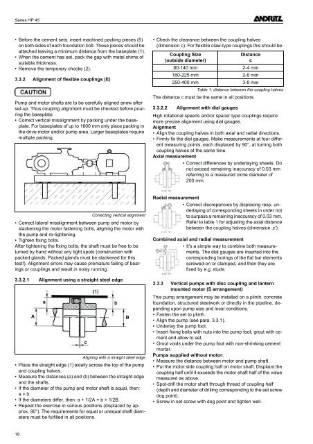
• Correct lateral misalignment between pump and motor by<br />
slackening the motor fastening bolts, aligning the motor with<br />
the pump and re-tightening.<br />
• Tighten fixing bolts.<br />
After tightening the fixing bolts, the shaft must be free to be<br />
turned by hand without any tight spots (construction with<br />
packed glands: Packed glands must be slackened for this<br />
test!). Alignment errors may cause premature failing of bearings<br />
or couplings and result in noisy running.<br />
3.3.2.1 Alignment using a straight steel edge<br />
Aligning with a straight steel edge<br />
• Place the straight edge (1) axially across the top of the pump<br />
and coupling halves.<br />
• Measure the distances (a) and (b) between the straight edge<br />
and the shafts.<br />
• If the diameter of the pump and motor shaft is equal, then:<br />
a = b.<br />
• If the diameters differ, then: a + 1/2A = b + 1/2B.<br />
• Repeat the exercise in various positions (displaced by approx.<br />
90°). The requirements for equal or unequal shaft diameters<br />
must be fulfilled in all positions.<br />
Radial measurement<br />
• Correct discrepancies by displacing resp. un<strong>de</strong>rlaying<br />
of corresponding sheets in or<strong>de</strong>r not<br />
to surpass a remaining inaccuracy of 0.03 mm.<br />
Refer to table 1 for adjusting the axial distance<br />
between the coupling halves (dimension ‚c').<br />
Combined axial and radial measurement<br />
• It's a simple way to combine both measurements.<br />
The dial gauges are inserted into the<br />
corresponding borings of the flat bar elements<br />
screwed-on or clamped, and then they are<br />
fixed by e.g. studs.<br />
3.3.3 Vertical pumps with disc coupling and lantern<br />
mounted motor (S arrangement)<br />
This pump arrangement may be installed on a plinth, concrete<br />
foundation, structured steelwork or directly in the pipeline, <strong>de</strong>pending<br />
upon pump size and local conditions.<br />
• Fasten the set to plinth.<br />
• Align the pump (see para. 3.3.1).<br />
• Un<strong>de</strong>rlay the pump foot.<br />
• Insert fixing bolts with nuts into the pump foot, grout with cement<br />
and allow to set.<br />
• Grout voids un<strong>de</strong>r the pump foot with non-shrinking cement<br />
mortar.<br />
Pumps supplied without motor:<br />
• Measure the distance between motor and pump shaft.<br />
• Put the motor si<strong>de</strong> coupling half on motor shaft. Displace the<br />
coupling half until it exceeds the motor shaft half of the value<br />
measured as above.<br />
• Spot-drill the motor shaft through thread of coupling half<br />
(<strong>de</strong>pth and diameter of drilling corresponding to the set screw<br />
dog point).<br />
• Screw in set screw with dog point and tighten well.<br />
18