Betriebsanleitung Operating Instructions Instructions de ... - Andritz
Betriebsanleitung Operating Instructions Instructions de ... - Andritz
Betriebsanleitung Operating Instructions Instructions de ... - Andritz

Create successful ePaper yourself
Turn your PDF publications into a flip-book with our unique Google optimized e-Paper software.
Series HP 45<br />
• Mount the pump si<strong>de</strong> coupling half to the motor coupling half<br />
and tighten the screw (see table). The screws of the disc coupling<br />
are to be secured by sticking.<br />
Thread [mm] Tightening moment [Nm]<br />
M8 36<br />
M12 125<br />
M16 305<br />
Table 2: Tightening moment for coupling screws<br />
• Mount motor with coupling onto motor stool, screw-down connection<br />
screws.<br />
• Adjust the pump rotor axially to centre.<br />
• Spot-drill the pump shaft through thread of fastening bolt.<br />
• Screw-in adjusting screw and tighten well.<br />
3.3.4 Pourring and other final checks<br />
• After aligning and fixing the pump set in position, pour the<br />
baseplate with rapid har<strong>de</strong>ning, non-shrinking cement mortar<br />
and consolidate it.<br />
• Allow to set for at least 48 hours.<br />
• Retighten the fixing bolts.<br />
• Check the alignment of pump and motor.<br />
3.4 Piping<br />
Non-binding suggestions for proper <strong>de</strong>sign and installation of<br />
the pipework (the exact <strong>de</strong>sign of the pipework must remain the<br />
responsibility of the project manager!).<br />
3.4.1 General<br />
• Provi<strong>de</strong> support for the piping on both si<strong>de</strong>s of the pump and<br />
attach it unstressed onto the pump. Please observe the max.<br />
permissible branch loads (refer to para. 7.2).<br />
• After the piping has been connected, check the running of the<br />
pump and alignment of coupling.<br />
• Use bellow expansion joints with linear reducers.<br />
• Alterations in the length of the piping caused by harsh temperatures<br />
and other strains can be prevented by the use of<br />
anchorages on both si<strong>de</strong>s of the pump.<br />
• The pipework should be short and direct and changes of direction<br />
should be avoi<strong>de</strong>d where possible.<br />
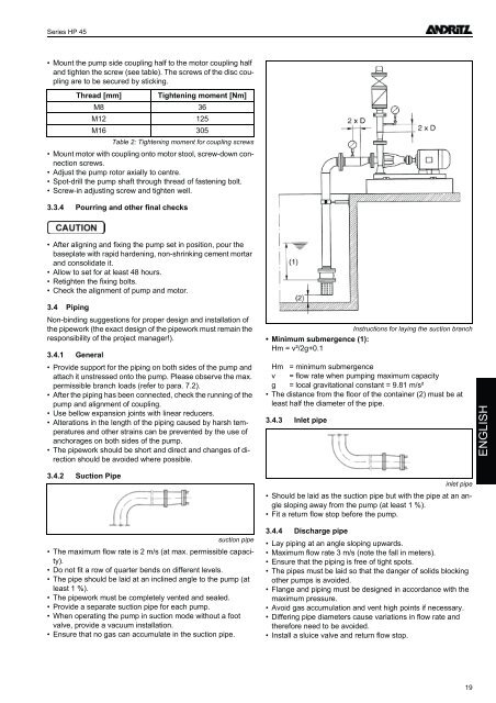
<strong>Instructions</strong> for laying the suction branch<br />
• Minimum submergence (1):<br />
Hm = v²/2g+0.1<br />
Hm = minimum submergence<br />
v = flow rate when pumping maximum capacity<br />
g = local gravitational constant = 9.81 m/s²<br />
• The distance from the floor of the container (2) must be at<br />
least half the diameter of the pipe.<br />
3.4.3 Inlet pipe<br />
ENGLISH<br />
3.4.2 Suction Pipe<br />
suction pipe<br />
• The maximum flow rate is 2 m/s (at max. permissible capacity).<br />
• Do not fit a row of quarter bends on different levels.<br />
• The pipe should be laid at an inclined angle to the pump (at<br />
least 1 %).<br />
• The pipework must be completely vented and sealed.<br />
• Provi<strong>de</strong> a separate suction pipe for each pump.<br />
• When operating the pump in suction mo<strong>de</strong> without a foot<br />
valve, provi<strong>de</strong> a vacuum installation.<br />
• Ensure that no gas can accumulate in the suction pipe.<br />
inlet pipe<br />
• Should be laid as the suction pipe but with the pipe at an angle<br />
sloping away from the pump (at least 1 %).<br />
• Fit a return flow stop before the pump.<br />
3.4.4 Discharge pipe<br />
• Lay piping at an angle sloping upwards.<br />
• Maximum flow rate 3 m/s (note the fall in meters).<br />
• Ensure that the piping is free of tight spots.<br />
• The pipes must be laid so that the danger of solids blocking<br />
other pumps is avoi<strong>de</strong>d.<br />
• Flange and piping must be <strong>de</strong>signed in accordance with the<br />
maximum pressure.<br />
• Avoid gas accumulation and vent high points if necessary.<br />
• Differing pipe diameters cause variations in flow rate and<br />
therefore need to be avoi<strong>de</strong>d.<br />
• Install a sluice valve and return flow stop.<br />
19