Betriebsanleitung Operating Instructions Instructions de ... - Andritz
Betriebsanleitung Operating Instructions Instructions de ... - Andritz
Betriebsanleitung Operating Instructions Instructions de ... - Andritz

You also want an ePaper? Increase the reach of your titles
YUMPU automatically turns print PDFs into web optimized ePapers that Google loves.
Series HP 45<br />
S<br />
Care and attention to <strong>de</strong>tail during installation are essential<br />
for a trouble-free operation. Incorrect procedures during<br />
installation may create hazards for personnel or<br />
property or lead to premature failure of the pump.<br />
3.1 Preliminary checks<br />
Check that the dimensions of the plinth/foundation are in accordance<br />
with the drawings.<br />
2.4 Dimensions, weights, centres of gravity, capacity<br />
Information on request.<br />
For weights refer to the contract documentation.<br />
2.5 Installation requirements<br />
• Protect motors and pumps from the weather.<br />
• Ensure that the workplace is a<strong>de</strong>quately ventilated/heated/<br />
cooled and observe noise protection requirements.<br />
• Check that the transport / taking away of the pump set or its<br />
components to / from installation site is possible without danger<br />
of acci<strong>de</strong>nt.<br />
Openings must be large enough.<br />
• A<strong>de</strong>quately rated lifting equipment must be available.<br />
3.2 Mounting of pump and motor (arrangement A)<br />
See also para. 3.3.<br />
• Common baseplate mounted pump and motor: Adjust the axial<br />
clearance between pump and motor shaft ends.<br />
• Separately mounted pump and motor: Secure the pump onto<br />
the plinth and align it. Then secure the motor and align it with<br />
the pump.<br />
3.3 Installation of assembled pump sets<br />
3.3.1 Horizontal pumps with base plate-mounted drive<br />
motors (E)<br />
• Before lowering the set into position clean the plinth surface<br />
and remove any limewash to ensure sound bonding.<br />
• Hang the fixing bolts with nuts in the baseplate fixing holes.<br />
• Lower the set into position on the plinth surface.<br />
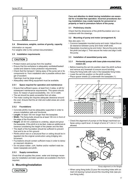
• Place spacer sheets (2) un<strong>de</strong>rneath the baseplate (1).<br />
(3)<br />
2.5.1 Space required for operation and maintenance<br />
• Ensure that sufficient space, at least from 2 si<strong>de</strong>s, is left for<br />
subsequent maintenance requirements. This space should<br />
have, for reason of good accessibility, min. 0.8 m width.<br />
• The set should be easily accessible from all si<strong>de</strong>s.<br />
• The motor cooling fan requires a<strong>de</strong>quate clearance around<br />
the cowl. Ensure that the air inlet and outlet areas are unobstructed.<br />
(2)<br />
(1)<br />
(6)<br />
(5)<br />
(4)<br />
2.5.2 Foundations<br />
• Concrete plinths must be a<strong>de</strong>quately supported in or<strong>de</strong>r to<br />
ensure installation safe and functional.<br />
• Length: At least 100 mm longer than the baseplate.<br />
• Width: The fixing bolts should be at least 100 mm in front of<br />
the edge of the foundation.<br />
• Height: 20-30 mm un<strong>de</strong>rsize to un<strong>de</strong>rlay, adjust and grout<br />
the baseplate. If the plinth is to be tiled, make an additional allowance<br />
consi<strong>de</strong>ring the height of the plaster and the tiles.<br />
• The <strong>de</strong>pth of the foundation should be sufficient to prevent<br />
frost and to be on firm ground.<br />
• Plinths which rest on a structural floor or ceiling should be integrated<br />
into the original construction using bridging reinforcement.<br />
• Foundations should contain sufficient mass in or<strong>de</strong>r to dampen<br />
resonant vibrations.<br />
• Do not place rubber, cork, feather and/or resilient mats between<br />
baseplate and plinth.<br />
Fixing bolts<br />
• Check the alignment of pumps on the flange machined surfaces<br />
using a spirit level. A margin of error of 1 mm in 1 m is<br />
allowed.<br />
(M)<br />
(M)<br />
ENGLISH<br />
2.5.3 Supply connections<br />
Check that all supplies like power, water and drainage necessary<br />
for installation and later operation are available in the form<br />
required.<br />
3. Mounting/installation<br />
Pump alignment on the flanges<br />
• When using fixing bolts (3) pour the mounting holes with cement<br />
(4) leaving it proud around the mounting hole (see picture<br />
fixing bolts).<br />
17