THP9045 Wiring Module - Honeywell ForwardThinking
THP9045 Wiring Module - Honeywell ForwardThinking
THP9045 Wiring Module - Honeywell ForwardThinking

Create successful ePaper yourself
Turn your PDF publications into a flip-book with our unique Google optimized e-Paper software.
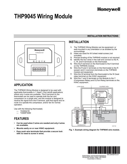
<strong>THP9045</strong> <strong>Wiring</strong> <strong>Module</strong><br />
APPLICATION<br />
<strong>THP9045</strong>A1007<br />
R C G Y K<br />
M27134<br />
INSTALLATION<br />
INSTALLATION INSTRUCTIONS<br />
1. The <strong>THP9045</strong> <strong>Wiring</strong> <strong>Module</strong> can be equipment- or<br />
wall-mounted in any orientation or as dictated by the<br />
surroundings.<br />
2. Holes are sized for # 6 sheet metal screws (not<br />
included).<br />
3. Precise leveling of the <strong>THP9045</strong> module is not required.<br />
4. Identify the four wires in the wall and connect to the R,<br />
C, W, and K terminals on the thermostat.<br />
5. Wire the K terminal on the thermostat to the K terminal<br />
on the <strong>THP9045</strong> module.<br />
6. Wire the R and C terminals on the thermostat to the R<br />
(power) and C (common) terminals on the <strong>THP9045</strong><br />
module and equipment.<br />
7. Wire the W terminal from the thermostat to the W (heat<br />
relay) terminal on the HVAC equipment.<br />
8. Wire the Y and G terminals on the <strong>Module</strong> to the Y<br />
(Compressor Relay) and G (Fan Relay) terminals on the<br />
HVAC equipment.<br />
LIVING SPACE<br />
EQUIPMENT AREA<br />
The <strong>THP9045</strong> <strong>Wiring</strong> <strong>Module</strong> is designed to be used with<br />
applicable thermostats in 1 Heat/1 Cool retrofit applications<br />
where only 4 wires are available. The K terminal on the<br />
thermostat can be used to operate both the fan and<br />
compressor on a single wire, and the module is designed to<br />
receive the signal from the K terminal, split that signal and reroute<br />
it to operate the compressor, and/or fan for normal<br />
operation.<br />
Use with the following thermostats:<br />
— THX9321R<br />
— T2060F3080<br />
FEATURES<br />
• Can be used when 5 wires are needed and only 4 wires<br />
are available.<br />
• Mounts easily on or near HVAC equipment.<br />
• Easy push wire terminals that provide a secure lock<br />
with no need to screw in wires.<br />
HEAT PUMP<br />
CONVENTIONAL<br />
O/B<br />
AUX/E<br />
Y<br />
Y2<br />
G<br />
L<br />
K<br />
1<br />
2<br />
3<br />
4<br />
5<br />
W<br />
W2<br />
Y<br />
Y2<br />
G<br />
6<br />
7 K<br />
8<br />
THERMOSTAT<br />
9<br />
10 C<br />
11 RC<br />
12 R<br />
13 HUM<br />
14 HUM<br />
15 DHUM<br />
16 DHUM<br />
SYSTEM<br />
POWER<br />
SYSTEM<br />
COMMON<br />
<strong>THP9045</strong>A1007<br />
R C G Y K<br />
FAN RELAY<br />
COMPRESSOR<br />
RELAY<br />
HVAC EQUIPMENT<br />
HEAT RELAY<br />
M27106<br />
Fig. 1. Example wiring diagram for <strong>THP9045</strong> wire module.<br />
Automation and Control Solutions<br />
<strong>Honeywell</strong> Golden Valley, MN 55422<br />
Assembled in Mexico<br />
69-2065EFS-01
<strong>Module</strong> de câblage <strong>THP9045</strong><br />
APPLICATION<br />
<strong>THP9045</strong>A1007<br />
R C G Y K<br />
M27134<br />
INSTALLATION<br />
DIRECTIVES D'INSTALLATION<br />
1. Le module <strong>THP9045</strong> peut être installé sur le système de<br />
CVCA ou sur un mur. Le sens de montage n'a pas<br />
d'importance et dépend l'emplacement.<br />
2. Trous pour des vis à tôle n o 6 (non fournies).<br />
3. Il n'est pas nécessaire d'installer le module <strong>THP9045</strong> de<br />
niveau.<br />
4. Identifier les quatre fils qui passent dans le mur et les<br />
raccorder aux bornes R, C, W et K du thermostat.<br />
5. Raccorder la borne K du thermostat à la borne K du<br />
module <strong>THP9045</strong>.<br />
6. Raccorder les bornes R et C du thermostat aux bornes<br />
R (alimentation) et C (neutre) du module <strong>THP9045</strong> et du<br />
système.<br />
7. Raccorder la borne W du thermostat à la borne W<br />
(relais de chauffage) sur le système de CVCA.<br />
8. Raccorder les bornes Y et G du module aux bornes Y<br />
(relais du compresseur) et G (relais du ventilateur) sur<br />
le système de CVCA.<br />
ZONE HABITÉE<br />
SYSTÈME<br />
Le module de câblage <strong>THP9045</strong> est conçu pour être utilisé<br />
avec les thermostats appropriés dans les applications de<br />
modernisation de systèmes à un étage de chauffage et un<br />
étage de refroidissement lorsque seulement quatre fils sont<br />
disponibles. La borne K du thermostat peut servir à faire<br />
fonctionner le ventilateur et le compresseur au moyen d'un<br />
seul fil. Le module, qui reçoit le signal de la borne K, sépare<br />
ce signal et le dirige pour faire fonctionner de façon normale<br />
le compresseur et le ventilateur.<br />
Ce module peut être utilisé avec les thermostats suivants :<br />
— THX9321R<br />
— T2060F3080<br />
CARACTÉRISTIQUES :<br />
• Peut être utilisé lorsque 5 fils sont requis mais<br />
seulement 4 fils sont disponibles.<br />
• S'installe facilement sur le système de CVCA ou à<br />
proximité.<br />
• Bornes pousse-fil permettant d'effectuer une<br />
connexion solide sans avoir à visser les fils.<br />
THERMOPOMPE<br />
TRADITIONNELLE<br />
O/B<br />
AUX/E<br />
Y<br />
Y2<br />
G<br />
L<br />
K<br />
1<br />
2<br />
3<br />
4<br />
5<br />
W<br />
W2<br />
Y<br />
Y2<br />
G<br />
6<br />
7<br />
8<br />
K<br />
14<br />
15<br />
16<br />
THERMOSTAT<br />
9<br />
10 C<br />
11 RC<br />
12 R<br />
13 HUM<br />
HUM<br />
DHUM<br />
DHUM<br />
ALIMENTATION<br />
DU SYSTÈME<br />
NEUTRE DU<br />
SYSTÈME<br />
<strong>THP9045</strong>A1007<br />
R C G Y K<br />
RELAIS DU<br />
VENTILATEUR<br />
RELAIS DU<br />
COMPRESSEUR<br />
SYSTÈME CVCA<br />
RELAIS DE<br />
CHAUFFAGE<br />
MF27106<br />
Fig. 1. Exemple de schéma de raccordement du module<br />
<strong>THP9045</strong>
Módulo de cableado <strong>THP9045</strong><br />
INSTRUCCIONES PARA LA INSTALACIÓN<br />
INSTALACIÓN<br />
APLICACIÓN<br />
<strong>THP9045</strong>A1007<br />
R C G Y K<br />
M27134<br />
1. El módulo de cableado <strong>THP9045</strong> puede montarse en<br />
equipo o en pared en cualquier orientación o como lo<br />
permita el entorno.<br />
2. Los agujeros están diseñados para tornillos No. 6 para<br />
lámina de metal (no se suministran).<br />
3. No es necesario nivelar de forma precisa el módulo<br />
<strong>THP9045</strong>.<br />
4. Identifique los cuatro cables en la pared y conéctelos a<br />
los terminales R, C, W, y K en el termostato.<br />
5. Cablee el terminal K en el termostato al terminal K en el<br />
módulo <strong>THP9045</strong>.<br />
6. Cablee los terminales R y C en el termostato a los terminales<br />
R (energía) y C (común) en el módulo<br />
<strong>THP9045</strong> y el equipo.<br />
7. Cablee el terminal W del termostato al terminal W (relé<br />
de calor) en el equipo HVAC.<br />
8. Cablee los terminales Y y G en el módulo a los terminales<br />
Y (relé del compresor) y G (relé del ventilador) en el<br />
equipo HVAC.<br />
El módulo de cableado <strong>THP9045</strong> está diseñado para ser<br />
usado con termostatos adecuados en aplicaciones de<br />
adaptación en 1 Calor/1 frío donde sólo estén disponibles 4<br />
cables. El terminal K del termostato puede utilizarse para que<br />
opere tanto el ventilador como el compresor con un solo cable<br />
y el módulo está diseñado para recibir la señal del terminal K,<br />
dividir esa señal y redirigirla para que opere el compresor, y/o<br />
el ventilador de manera normal.<br />
ÁREA HABITABLE<br />
ÁREA DEL EQUIPO<br />
<strong>THP9045</strong>A1007<br />
R C G Y K<br />
Utilice con los siguientes termostatos:<br />
— THX9321R<br />
— T2060F3080<br />
CARACTERÍSTICAS<br />
• Puede utilizarse cuando se necesiten 5 cables y<br />
existan sólo 4 disponibles.<br />
• Se monta fácilmente en o cerca de un equipo HVAC.<br />
• Terminales de cable de inserción fácil que<br />
proporcionan una conexión segura sin necesidad de<br />
retorcer los cables.<br />
BOMBA DE CALOR<br />
CONVENCIONAL<br />
O/B<br />
AUX/E<br />
Y<br />
Y2<br />
G<br />
L<br />
K<br />
1<br />
2<br />
3<br />
4<br />
5<br />
W<br />
W2<br />
Y<br />
Y2<br />
G<br />
6<br />
7 K<br />
8<br />
TERMOSTATO<br />
9<br />
10 C<br />
11 RC<br />
12 R<br />
13 HUM<br />
14 HUM<br />
15 DHUM<br />
16 DHUM<br />
ENERGÍA<br />
DEL SISTEMA<br />
COMÚN<br />
DEL SISTEMA<br />
RELÉ DEL<br />
COMPRESOR<br />
RELÉ DEL VENTILADOR<br />
EQUIPO HVAC<br />
RELÉ DE<br />
CALOR<br />
MS27106<br />
Fig. 1. Fig. 1. Ejemplo del diagrama de cableado para el<br />
módulo de cableado <strong>THP9045</strong>.
<strong>THP9045</strong> WIRING MODULE<br />
Automation and Control Solutions<br />
<strong>Honeywell</strong> International Inc. <strong>Honeywell</strong> Limited-<strong>Honeywell</strong> Limitée<br />
1985 Douglas Drive North 35 Dynamic Drive<br />
Golden Valley, MN 55422 Toronto, Ontario M1V 4Z9<br />
customer.honeywell.com<br />
Solutions de régulation et d’automatisation<br />
<strong>Honeywell</strong> International Inc. <strong>Honeywell</strong> Limited-<strong>Honeywell</strong> Limitée<br />
1985 Douglas Drive North 35, Dynamic Drive<br />
Golden Valley, MN 55422 Toronto (Ontario) M1V 4Z9<br />
customer.honeywell.com<br />
® Marque de commerce déposée aux É.-U.<br />
© 2007 <strong>Honeywell</strong> International Inc. Tous droits réservés<br />
Automatización y control desenlace<br />
<strong>Honeywell</strong> International Inc. <strong>Honeywell</strong> Limited-<strong>Honeywell</strong> Limitée<br />
1985 Douglas Drive North 35, Dynamic Drive<br />
Golden Valley, MN 55422 Toronto, Ontario M1V 4Z9<br />
customer.honeywell.com<br />
® Marca Registrada en los E.U.A<br />
© 2007 <strong>Honeywell</strong> International Inc. todos Los Derechos Reservados<br />
® U.S. Registered Trademark<br />
© 2007 <strong>Honeywell</strong> International Inc.<br />
69-2065EFS—01 M.S. 12-07