Manual Totaline P474-0130
Manual Totaline P474-0130
Manual Totaline P474-0130

You also want an ePaper? Increase the reach of your titles
YUMPU automatically turns print PDFs into web optimized ePapers that Google loves.
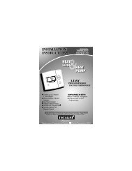
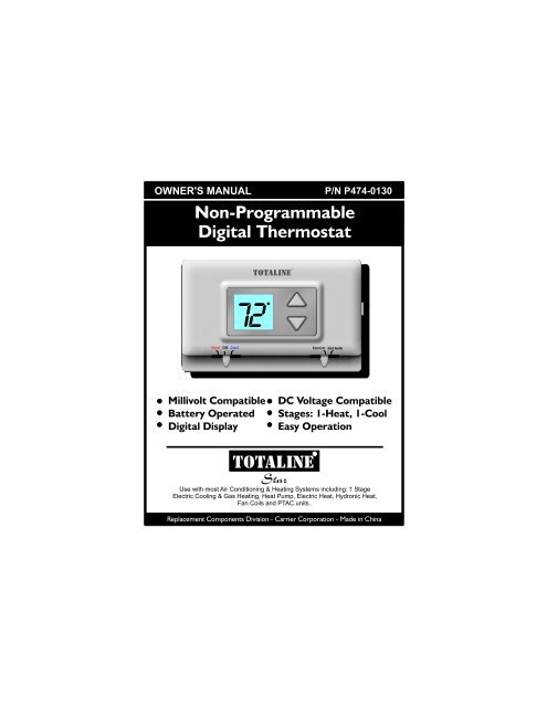
OWNER'S MANUAL P/N <strong>P474</strong>-<strong>0130</strong>Non-ProgrammableDigital ThermostatTOTALINE72Millivolt CompatibleBattery OperatedDigital DisplayDC Voltage CompatibleStages: 1-Heat, 1-CoolEasy OperationTOTALINEStarUse with most Air Conditioning & Heating Systems including: 1 StageElectric Cooling & Gas Heating, Heat Pump, Electric Heat, Hydronic Heat,Fan Coils and PTAC units..Replacement Components Division - Carrier Corporation - Made in China
OWNER'S MANUALDIGITAL THERMOSTATContentsSafety WarningsLocation of ControlsDisplayNormal OperationPreparationRemove Old ThermostatInstallation/BatteryReplacementWire ConnectionsJumper ConfigurationTest OperationTroubleshootingWarrantyPage 2Page 2Page #
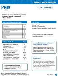
INSTALLATION INSTRUCTIONSSafety WarningsCAUTIONP/N <strong>P474</strong>-<strong>0130</strong>Follow Installation Instructions carefully.DISCONNECT POWER TO THE HEATER -AIR CONDITIONER BEFORE REMOVINGTHE OLD THERMOSTAT AND INSTALLINGTHE NEW THERMOSTAT.WARNINGCAUTIONThe 2 Alkaline “AA” batteries must be replaced at leastevery 12 months to assure proper operation.The thermostat will display the Low Batterycode (fig. 1) on the display of the thermostatwhen it is time to replace the batteries.FIG. 1When is displayed the batteries must be replacedimmediately. The manufacturer cannot be liable forimproper operation of the thermostat if the batteries arenot immediately replaced.The annual battery replacement is especially critical inlocations subject to freezing temperatures. Thethermostat will be unable to turn on the Heat if thebatteries are exhausted.This device complies with Part 15 of the FCC rules.Operation is subject to the following 2 conditions:(1) This device may not cause harmful interference, and (2)This device must accept any interference received, includinginterference that may cause undesired operation.Replacement Components Division Carrier Corporation Patents PendingPage 3
OWNER'S MANUALDIGITAL THERMOSTATDisplaySET TEMP78 74Current room temperature.If the Up or Down arrow buttons are pressed thethermostat will show the desired Set Temp temperatureindicator. Once this screen is reached you may use theUp or Down arrow buttons to adjust the desired roomtemperature.After five seconds with no button presses thethermostat will revert back to show the currentroom temperature.Page 5Page 5
OWNER'S MANUALDIGITAL THERMOSTATNormal Operation72TOTALINEUP & DOWNBUTTONSMODE SWITCHHeat, Cool or Off<strong>Manual</strong> OperationFAN SWITCHOn or AutoSelect Heat or Cool with the mode switch.Normally leave the fan switched to Fan Auto.In Fan Auto, the fan will turn on only with a heator cool demand. When Fan On is selected, thefan will run continuously, even when the modeswitch is set to Off.Adjust the desired set temperature with theUp or Down buttons.Page 6
Heat Off CoolHeat Off CoolHeat Off CoolHeat Off CoolHeat Off CoolTOTALINETOTALINETOTALINETOTALINETOTALINEFan On FanAutoFan On FanAutoFan On FanAutoFan On FanAutoFan On FanAutoINSTALLATION INSTRUCTIONSStep #1Preparation7272Proper installation of the thermostat will beaccomplished by following these stepby step instructions. If you are unsureabout any of these steps, call a qualifiedtechnician for assistance.These tools will be required:727272Flat BladeScrewdriverWire cutter& StripperMake sure your Heater/Air Conditioneris working properly before beginninginstallation of the thermostat.Carefully unpack the thermostat.Save the screws and instructions.Turn off the power to the Heating/AirConditioning system at the main fusepanel. Most residential systems havea separate breaker for disconnectingpower to the furnace.Page 7
Heat Off CoolHeat Off CoolHeat Off CoolHeat Off CoolTOTALINETOTALINETOTALINETOTALINEFan On FanAutoFan On FanAutoFan On FanAutoFan On FanAutoINSTALLATION INSTRUCTIONSStep #2Remove & ReplaceOld Thermostat7272Remove the cover of the old thermostat.If it does not come off easily check forscrews.Loosen the screws holding the thermostatbase or subbase to the wall, and lift away.7272Disconnect the wires from the oldthermostat. Tape the ends of the wiresas you disconnect them, and mark themwith the letter of the terminal for easyreconnection to the new thermostat.Keep the old thermostat for referencepurposes, until your new thermostat isfunctioning properly.Page 8
INSTALLATION INSTRUCTIONSStep #3Open The New ThermostatInstallation / BatteryReplacementThe top of the thermostat housing has two (2) screwdriverslots to assist when seperating.SCREWDRIVERSLOTSTo pull the housing apart, insert a small blade screwdriverinto the slot and rotate 90 . This will releasethe top housing snaps.Repeat the procedure in the other screw driver slot.Separate the housing halves by pulling the topforward until the pins release, and then lift the bottomout.The batteries must be replacedimmediately when the thermostatdisplays the Low Battery code (fig.1).Page 9FIG. 1
INSTALLATION INSTRUCTIONSBattery ReplacementREPLACE WITH ALKALINE BATTERIES AT LEAST ONCEEVERY YEAR, OR WHEN THE “LOW BATTERY” ICONAPPEARS (pages 3,9).POSITION BATTERIES AS SHOWNUSE “AA” SIZEALKALINE BATTERIESUSE “AA” SIZEALKALINE BATTERIESFAN W/ HEATJ1123J2HEAT PUMP3 2 1Page 10
Heat Off CoolTOTALINEFan On FanAuto4Z95INSTALLATION INSTRUCTIONSStep #4Wire Connections72If the terminal designations on your oldthermostat do not match those on thenew thermostat, refer to the chart below,or the wiring diagrams that follow.Wire from theold thermostatterminal markedFunctionInstall on thenew thermostatconnector markedW1, W or H Heating WY1 or Y Cooling YBRev. Valve(Energize to Heat)BO Rev. ValveO(Energize to Cool)G or F Fan GRh, R, M, Vr, APowerThermal Insulating SheetRA label is provided on the backplatethat prevents drafts, originating insidethe wall, from entering the thermostat.These drafts, left unchecked, maycause incorrect room temperaturereadings.Please do not remove this labelfrom the thermostat. Insert the wiresthrough the slots provided in the labelas shown in Fig. 1Wire SlotsPage 11WYBOGRMODEL: <strong>P474</strong>-<strong>0130</strong>97061606USE SIZE “AA”ALKALINE BATTERIES MADE IN CHINAFig. 1
INSTALLATION INSTRUCTIONSSample Wiring DiagramsGas or Electric Heat4 Wire, 1 Stage Cooling, 1 Stage Gas Heat Residential Gas or Electric Heat *,Electric Cool, split systems & packageunitsWYBOGR4 Conductor 18 to 22 gaugeunshielded cable from thethermostat to the equipment.POWERFANCOMPRESSORGAS ORELECTRIC HEATW Y G RPage 12
INSTALLATION INSTRUCTIONSSample Wiring DiagramsGas or Electric Heat4 Wire, 1 Stage Cooling, 1 Stage Heat-Heat Pump with O reversing valve.Residential Heat Pumps, split systems & package units, with no auxiliary heat.WYBOGR4 Conductor 18 to 22 gaugeunshielded cable from thethermostat to the equipment.POWERFANREVERSING VALVECOMPRESSORG ROYPage 13
INSTALLATION INSTRUCTIONSSample Wiring DiagramsGas or Electric Heat4 Wire, 1 Stage Cooling, 1 Stage Heat-Heat Pump with B reversing valve.Residential Heat Pumps, split systems & package units, with no auxiliary heat.WYBOGR4 Conductor 18 to 22 gaugeunshielded cable from thethermostat to the equipment.POWERFANREVERSING VALVECOMPRESSORG RBYPage 14
INSTALLATION INSTRUCTIONSSample Wiring DiagramsGas or Electric Heat3 Wire, 1 Stage Heat Residential Gas or Electric Heat unitswith a separately controlled fan.WYBOGR3 Conductor 18 to 22 gaugeunshielded cable from thethermostat to the equipment.POWERFANGAS ORELECTRIC HEATG RWPage 15
INSTALLATION INSTRUCTIONSSample Wiring DiagramsGas or Electric Heat2 Wire, 1 Stage Gas Heat Residential Gas or Millivolt units.WYBOGR2 Conductor 18 to 22 gaugeunshielded cable from thethermostat to the equipment.POWERGAS ORELECTRIC HEATW RPage 16
INSTALLATION INSTRUCTIONSSample Wiring DiagramsGas or Electric Heat3 Wire, 1 Stage Cooling Residential Electric Cool unitsWYBOGR3 Conductor 18 to 22 gaugeunshielded cable from thethermostat to the equipment.POWERFANG RCOOLINGYPage 17
Heat Off CoolHeat Off CoolTOTALINETOTALINEFan On FanAutoFan On FanAutoINSTALLATION INSTRUCTIONSStep #5JumperConfigurationREPLACE WITH ALKALINEBATTERIES ONCE EVERY YEARUSE “AA” SIZEALKALINE BATTERIESUSE “AA” SIZEALKALINE BATTERIESFAN W/ HEATON12OFF3HEAT PUMPONOFF3217272If the HVAC unit has First Stage Electric Heatthen jumper should be set to ON. If thejumper is set for Fan w/ Heat On, the fan willenergize immediately on a call for heating.For all other applications this jumper shouldremain set to the OFF position.If the HVAC unit is a Heat Pump, then jumpershould be set to ON. For all other applicationsthis jumper should remain set to theOFF position.Page 18
Heat Off CoolHeat Off CoolHeat Off CoolHeat Off CoolTOTALINETOTALINETOTALINETOTALINEFan On FanAutoFan On FanAutoFan On FanAutoFan On FanAutoINSTALLATION INSTRUCTIONSStep #6Test Operation72Turn on the power to the Heating/AirConditioning system.72Adjust the Slide Switch until it is locatedunder the word HEAT on the thermostat.Press the Up or Down buttons until the settemperature is 10 degrees above roomtemperature. The HVAC unit shouldenergize in the heating mode (pages 5-6).7272Adjust the Slide Switch until it is locatedunder the word COOL on the thermostat.Press the Up or Down buttons until the settemperature is 10 degrees below roomtemperature. The HVAC unit shouldenergize in the cooling mode (pages 5-6).Adjust the Slide Switch until it is locatedunder the word OFF. Adjust the other slideswitch until it is located under the word FanOn. The fan should turn on and runcontinuously (pages 5-6).Page 19
Heat Off CoolHeat Off CoolTOTALINETOTALINEFan On FanAutoFan On FanAutoINSTALLATION INSTRUCTIONSTrouble Shooting72SYMPTOM: The slide switches on the thermostatare very difficult to move.CAUSE: The backplate of the thermostat isdeformed by being screwed tightly into awall that is not perfectly flat.REMEDY: Loosen the screws holding thethermostat into the wall.72SYMPTOM: The air conditioning does notattempt to turn on.CAUSE: The cooling setpoint is set toohigh or the Mode Switch is not set forCool, or the batteries are too weak.REMEDY: Consult the Normal Operationsection of this manual to lower thecooling setpoint and to correct theMode Switch position, orreplace the batteries (page 10).Page 20
Heat Off CoolTOTALINEFan On FanAutoINSTALLATION INSTRUCTIONSTrouble Shooting72SYMPTOM: The heating does not attemptto turn on.CAUSE: The heating setpoint is set toolow or the Mode Switch is not set forHeat, or the batteries are too weak.REMEDY: Consult the Normal Operationsection in this manuals to raise theheating setpoint and to correct theMode Switch position (page 10), orreplace the batteries.4Z95Battery Stat P/N <strong>P474</strong>-<strong>0130</strong>FCcTested to Complywith FCC StandardsFOR HOME OR OFFICE USEPage 21P/N 88-396Rev. 2
INSTALLATION INSTRUCTIONSWarrantyOne-Year Warranty - This Product is warranted to be free from defects in material andworkmanship. If it appears within one year from the date of original installation, whether ornot actual use begins on that date, that the product does not meet this warranty, a new orremanufactured part, at the manufacturer’s sole option, to replace any defective part willbe provided without charge for the part itself; PROVIDED the defective part is returned tothe distributor through a qualified servicing dealer.THIS WARRANTY DOES NOT INCLUDE LABOR OR OTHER COSTS incurred for diagnosing, repairing,removing, installing, shipping, servicing or handling of either defective parts or replacementparts. Such costs may be covered by a separate warranty provided by the installer.THIS WARRANTY APPLIES ONLY TO PRODUCTS IN THEIR ORIGINALINSTALLATION LOCATION AND BECOMES VOID UPON REINSTALLATION.LIMITATIONS OF WARRANTIES – ALL IMPLIED WARRANTIES (INCLUDING IMPLIEDWARRANTIES OF FITNESS FOR A PARTICULAR PURPOSE AND MERCHANTABILITY)ARE HEREBY LIMITED IN DURATION TO THE PERIOD FOR WHICH THE LIMITEDWARRANTY IS GIVEN. SOME STATES DO NOT ALLOW LIMITATIONS ON HOWLONG AN IMPLIED WARRANTY LASTS, SO THE ABOVE MAY NOT APPLY TO YOU.THE EXPRESSED WARRANTIES MADE IN THIS WARRANTY ARE EXCLUSIVE ANDMANY NOT BE ALTERED, ENLARGED, OR CHANGED BY ANY DISTRIBUTOR,DEALER, OR OTHER PERSON WHATSOEVER.ALL WORK UNDER THE TERMS OF THIS WARRANTY SHALL BE PERFORMEDDURING NORMAL WORKING HOURS. ALL REPLACEMENT PARTS, WHETHERNEW OR REMANUFACTURED, ASSUME AS THEIR WARRANTY PERIOD ONLY THEREMAINING TIME PERIOD OF THIS WARRANTY.THE MANUFACTURER WILL NOT BE RESPONSIBLE FOR:1. Normal maintenance as outlined in the installation and servicing instructions or ownersmanual including filter cleaning and/or replacement and lubrication.2. Damage or repairs required as a consequence of faulty installation, misapplication,abuse, improper servicing, unauthorized alteration or improper operation.3. Failure to start due to voltage conditions, blown fuses, open circuit breakers or otherdamages due to the inadequacy or interruption of electrical service.4. Damage as a result of floods, winds, fires, lightning, accidents, corrosive environments orother conditions beyond the control of the Manufacturer.5. Parts not supplied or designated by the Manufacturer, or damages resulting from theiruse.6. Manufacturer products installed outside the continental U.S.A., Alaska, Hawaii, andCanada.7. Electricity or fuel costs or increases in electricity or fuel costs from any reason whatsoeverincluding additional or unusual use of supplemental electric heat.8. ANY SPECIAL INDIRECT OR CONSEQUENTIAL PROPERTY OR COMMERCIALDAMAGE OF ANY NATURE WHATSOEVER. Some states do not allow the exclusion ofincidental or consequential damages, so the above may not apply to you.This warranty gives you specific legal rights, and you may also have other rights which mayvary form state to state.Page 22