Manual Install Slimline P374-1900 Rev. 1
Manual Install Slimline P374-1900 Rev. 1
Manual Install Slimline P374-1900 Rev. 1

You also want an ePaper? Increase the reach of your titles
YUMPU automatically turns print PDFs into web optimized ePapers that Google loves.
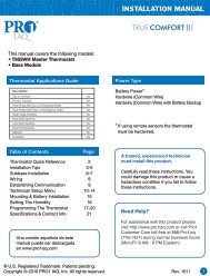
INSTALLATIONINSTRUCTIONSRESIDENTIALTHERMOSTATP/N <strong>P374</strong>- <strong>1900</strong>SuAUTO0I20:Pm74C OLHEATTOTALINE273 Configurable OutputsControl up to 3 Heat &2 Cool StagesAdjustable 2nd & 3rd StageTimers & DeadbandsBacklit Display & ButtonLegendsAux Heat IndicatorDry Contact EquippedOutdoor Sensor Readywith High/Low Readoutsfor the DayHEATCOOLTOTALINESignatureHEATPUMPDUALFUEL CAPABLE7-DAYPROGRAMMABLEDIGITALTHERMOSTATwithHUMIDITYCONTROLAccepts Optional Humidity Module:Controls Humidification,Dehumidification and ReheatProgrammable OutputAccepts EZ ProgrammerAccepts Optional IR Remote ControlOptional Internet / Phone ControlAccessoryEquipped withHumidity ModuleMeets Residential California Title 24Use with most Air Conditioning & Heating Systems including: 1 or 2 StageElectric Cooling & 3 Stage Gas Heating, Heat Pump, Electric or Hydronic Heat.Replacement Components Division Carrier Corporation 08/05
CAUTIONTOTALINEFollow the <strong>Install</strong>ation Instructions before proceeding.Set the thermostat mode to “OFF” prior to changingsettings in setup or restoring Factory Defaults.CAUTIONNEVER PUT MORE THAN ONEJUMPER ON THE SAME MISCJUMPER BLOCK!THIS MAY DAMAGE YOURTHERMOSTAT AND VOIDYOUR WARRANTY.MISC3OKMISC3NOTE: Due to variations in environmental conditions, it is notalways possible to achieve the desired humidification ordehumidification setpoint.This device complies with Part 15 of the FCC Rules. Operation issubject to the following two conditions: (1) this device may not causeharmful interference, and (2) this device must accept any interferencereceived, including interference that may cause undesired operation.4Z95Thermostat <strong>P374</strong>-<strong>1900</strong>FCcTested to Complywith FCC StandardsFOR HOME OR OFFICE USEPage i
Table of ContentsPreparationRemove & Replace theOld ThermostatConfiguring the MISCOutputsWire ConnectionsWiring DiagramsTest OperationTOTALINECalibrating theThermostat SensorsTroubleShooting12345678Page iii
SECTION 1Preparation1TOTALINEProper installation of the thermostat will beaccomplished by following these step by stepinstructions. If you are unsure about any of thesesteps, call a qualified technician for assistance.Assemble toolsFlat BladeScrewdriverWire cutter& StripperMake sure your Heater/Air Conditioner is workingproperly before beginning installation of thethermostat.Carefully unpack the thermostat. Save the screws,bracket, and instructions.Turn off the power to the Heating/Air Conditioningsystem at the main fuse panel. Most residentialsystems have a separate breaker for disconnectingpower to the furnace.Page 1.1
SECTION 2Remove & Replace the Old Thermostat TOTALINE 2Remove the cover of the old thermostat.If it does not come off easily check for screws.Loosen the screws holding the thermostatbase or subbase to the wall, and lift away.Disconnect the wires from the old thermostat.Tape the ends of the wires as you disconnectthem, and mark them with the letter of theterminal for easy reconnection to the newthermostat.Keep the old thermostat for reference purposes,until your new thermostat is functioning properly.Page 2.1
SECTION 3Configuring the MISC OutputsTOTALINE3Section 3 Contents:Configuring the Jumpers........3.2Explanation of JumperSettings..................................3.3Page 3.1
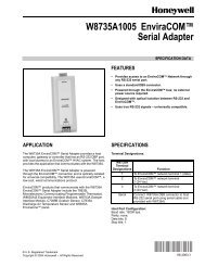
W3PROGHUMDEHUMMISC3 MISC2 MISC1 ONLY)21436587X19ZYELECGASHPGASBOConfiguring the JumpersTOTALINEFor additional flexibility, your thermostat has three configurableoutputs. These outputs are designed to have different functions3depending on how the jumpers are set (below).Each output, labeled MISC1, MISC2, and MISC3 may be set for oneof the five choices available.In the diagram below, the MISC3 jumper has been set for HUM(humidification) operation, the MISC2 jumper has been set for DEHUM(dehumidification) operation, and the MISC1 jumper has been set forPROG (programmable) operation.(FAN)W3PROGW1Y1GMISC2CK1CKGNDRCY2(MISC1HUMNO HUMINSTALL HUMIDITYMODULE WITH SENSINGELEMENT OUTWARDW2MISC1RS2MISC3RS+5Rs1RSGNDHUMDEHUMMISC3 MISC2 MISC1Y2(MISC1ONLY)CAUTIONNEVER PUT MORE THANONE JUMPER ON THE SAMEMISC JUMPER BLOCK!DOING SO MAY DAMAGEYOUR THERMOSTAT ANDVOID THE WARRANTY.Page 3.2MISC3OKMISC3
Explanation of Jumper SettingsTOTALINE3W3 JUMPER SETTINGIf the jumper for MISC1, MISC2, or MISC3 is set to W3, the corresponding MISCscrew terminal on the backplate will control a third stage of heat.W3 MULTI-STAGE OPERATION EXPLAINED - SECTION 14 of the Owner’s<strong>Manual</strong>The 3rd Stage of Heat is turned on when:(A) The 1st and 2nd stages have been on for the time required (steps 27Andand 28, page 14.6). It is adjustable from 0-60 minutes and the defaultis two minutes.(B) The temperature from the setpoint is equal to or greater than: the setpointplus the 1st stage deadband (step #24, 14.5), plus the 2nd stagedeadband (step #25, 14.5) plus the 3rd stage deadband (step #26,14.5). This 3rd stage deadband is adjustable from 0-10 degrees andthe default is two degrees.DeadbandHeatingCoolingDeadband Deadband Deadband Deadbanddb 3db 2 db 1 db 1 db 2(adj. 0-10 ) (adj. 0-10 ) (adj. 1-6 )(adj. 1-6 ) (adj. 0-10 )3rd Stageturn on2nd Stageturn on1st Stageturn onHeatSetpointCoolSetpoint1st Stageturn on2nd Stageturn onDECREASETEMPERATUREINCREASEPROG JUMPER SETTINGIf the jumper for MISC1, MISC2, or MISC3 is set to PROG, the corresponding MISC screwterminal on the backplate will control a pilot relay or other accessory.PROGRAMMABLE OUTPUT - SECTION 15 of the Owner’s <strong>Manual</strong>This jumper setting allows the MISC outputs to control a pilot relay by time,temperature, or a signal from the Internet/Phone. The following are threepossible scenarios:By Time: A device that requires a start and stop time. An exampleof this would be an exterior lighting system that needed to beenergized every day between the hours of 8pm and 1am.By Temperature: An exhaust fan that needs to energize wheneverthe temperature from RS2 rises above 90 degrees F.By Remote: Remotely arming a security system through the web or phone.Page 3.3
TOTALINEExplanation of Jumper Settings (continued)HUM JUMPER SETTINGIf the jumper for MISC1, MISC2, or MISC3 is set to HUM, the corresponding MISC screwterminal on the backplate will control a humidification system.3HUMIDIFICATION OPERATION - SECTION 9 of the Owner’s <strong>Manual</strong>If your HVAC unit is equipped with a humidification system the thermostat willprovide power to the MISC1, MISC2, or MISC3 terminal of the thermostat whenthe humidity in the home falls below the humidity setpoint you have chosen.The value for this setpoint ranges from 0% to 60%. If no humidity is desiredor if a humidification system has not been installed, set the value to OFF.DEHUM JUMPER SETTINGIf the jumper for MISC1, MISC2, or MISC3 is set to DEHUM, the corresponding MISC screwterminal on the backplate will be connected to the dehumidification terminal of a furnace board.NOTE: Not all furnaces have a dehumidification terminal.DEHUMIDIFICATION OPERATION - SECTION 10 of the Owner’s <strong>Manual</strong>If your HVAC unit is equipped with a dehumidification system the thermostat willoperate in one of two ways.1) Normally Closed (NC): The thermostat will de-energize the MISC1, MISC2,or MISC3 terminal of the thermostat (this MISC terminal is connected to theDEHUM terminal on your furnace) to allow the fan to run in low speed whenthe humidity in the home is above the dehumidify setpoint you have chosenand there is a call for 1st stage cooling.2) Normally Open (NO): The thermostat will energize the MISC1, MISC2, orMISC3 terminal of the thermostat (this MISC terminal is connected to theDEHUM terminal on your furnace) to allow the fan to run in low speed whenthe humidity in the home is above the dehumidify setpoint you have chosenand there is a call for 1st stage cooling.Page 3.4
TOTALINEExplanation of Jumper Settings (continued)3 Y2 JUMPER SETTINGIf the jumper for MISC1 is set to Y2 the MISC1 screw terminal on the backplatewill control a second stage of cooling.Y2 OPERATION - SECTION 14 of the Owner’s <strong>Manual</strong>Control up to two Cool stages.The 2nd Stage of heat or cool is turned on when:(A) The 1st Stage has been on for the time required (step #27,page 14.6). It is adjustable from 0-60 minutes and the defaultis two minutes.And(B) The temperature spread from the setpoint is equal to or greaterthan: the setpoint plus the deadband (step #24, page 14.5), plusthe 2nd deadband (step #25, page 14.5). This 2nd deadband isadjustable from 0-10 degrees and the default is two degrees.CoolingDeadband Deadbanddb 1 db 2(adj. 1-6 ) (adj. 0-10 )CoolSetpointTEMPERATURE1st Stageturn onINCREASE2nd Stageturn onPage 3.5
SECTION 4Wire ConnectionsTOTALINEIf the terminal designations on your old thermostatdo not match those on the new thermostat, referto the chart below, or the wiring diagrams 4that follow.Wire from theold thermostatterminal markedFunction<strong>Install</strong> on thenew thermostatconnector markedG or F Fan GY1, Y or C Cooling Y1W1, W or H Heating W1/O/BRh, R, M, Vr, A PowerRCO/BCommon<strong>Rev</strong>. ValveCW1/O/B**W2MISC1MISC2MISC32nd Stage HeatConfigurable Output #1Configurable Output #2Configurable Output #3W2MISC1MISC2MISC3RS+5 Remote Sensor +5vdcRS+5RS1Remote Sensor SignalRS1RSGND Remote Sensor Ground RSGNDRS2Remote Sensor Signal #2RS2CK1 Dry Contact Switch 1 CK1CKGND Dry Contact Switch 2CKGND** O/B is used if your system is a Heat Pump.Page 4.1
SECTION 5Sample Wiring DiagramsTOTALINESection 5 Contents:5HVAC Equipment Wiring............5.2MISC1, MISC2, and MISC3Wiring........................................5.6Remote Sensor and CK1-CK2wiring for Time Clock...............5.8Page 5.1
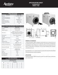
W3PROGHUMDEHUMW1Y1GMISC2CK1CKGNDRCY2(MISC1MISC3 MISC2 MISC1 ONLY)HUM2468XZ1INSTALL HUMIDITYMODULE WITH SENSINGELEMENT OUTWARD13579YELECGASHPGASBOW2MISC1RS2MISC3RS+5Rs1RSGNDTOTALINE6 Wire, 1 Stage Cooling, 1 Stage HeatResidential & Commercial 1 Stage Cooling,with 1st stage Gas HeatORCommercial Heat Pump 1 Stage Coolingwith 2 Stage Heat5ELECGAS(FAN)W2MISC1RS2MISC3RS+5RS1RSGNDW1/O/BY1GMISC2CK1CKGNDRCHPGASBONO HUM(FAN)6 Conductor 18 gaugeunshielded cable from thethermostat to the equipment.24 vac common24 vac returnfan relaycompressor relay1st stage heat circuit2nd stage heat circuitW2 W1 Y1 G R CPage 5.2
W3PROGHUMDEHUMW1Y1GMISC2CK1CKGNDRCY2(MISC1MISC3 MISC2 MISC1 ONLY)HUM2468XZ1INSTALL HUMIDITYMODULE WITH SENSINGELEMENT OUTWARD13579YELECGASHPGASBOW2MISC1RS2MISC3RS+5Rs1RSGNDTOTALINE6 Wire, 1 Stage Cooling, 1 Stage HeatResidential & Commercial 1 Stage Cooling,with 1st stage Electric Heat5ELECGAS(FAN)W2MISC1RS2MISC3RS+5RS1RSGNDW1/O/BY1GMISC2CK1CKGNDRCHPGASBONO HUM(FAN)6 Conductor 18 gaugeunshielded cable from thethermostat to the equipment.24 vac common24 vac returnfan relaycompressor relay1st stage heat circuit2nd stage heat circuitW2 W1 Y1 G R CPage 5.3
W3PROGHUMDEHUMW1Y1GMISC2CK1CKGNDRCY2(MISC1MISC3 MISC2 MISC1 ONLY)HUM2468XZ1INSTALL HUMIDITYMODULE WITH SENSINGELEMENT OUTWARD13579YELECGASHPGASBOW2MISC1RS2MISC3RS+5Rs1RSGNDTOTALINE6 Wire, 1 Stage Cooling, 2 Stage HeatResidential Heat Pump with O <strong>Rev</strong>ersingValve 1 Stage Cooling, with 2 stage Heat5ELECGAS(FAN)W2MISC1RS2MISC3RS+5RS1RSGNDW1/O/BY1GMISC2CK1CKGNDRCHPGASBONO HUM(FAN)6 Conductor 18 gaugeunshielded cable from thethermostat to the equipment.24 vac common24 vac returnFan RelayCompressor Relay<strong>Rev</strong>ersing Valve2nd stage heat circuitW2 O Y1 G R CPage 5.4
W3PROGHUMDEHUMW1Y1GMISC2CK1CKGNDRCY2(MISC1MISC3 MISC2 MISC1 ONLY)HUM2468XZ1INSTALL HUMIDITYMODULE WITH SENSINGELEMENT OUTWARD13579YELECGASHPGASBOW2MISC1RS2MISC3RS+5Rs1RSGNDTOTALINE6 Wire, 1 Stage Cooling, 2 Stage HeatResidential Heat Pump with b <strong>Rev</strong>ersingValve 1 Stage Cooling, with 2 stage Heat5ELECGAS(FAN)W2MISC1RS2MISC3RS+5RS1RSGNDW1/O/BY1GMISC2CK1CKGNDRCHPGASBONO HUM(FAN)6 Conductor 18 gaugeunshielded cable from thethermostat to the equipment.24 vac common24 vac returnFan RelayCompressor Relay<strong>Rev</strong>ersing Valve2nd stage heat circuitW2 b Y1 G R CPage 5.5
W3PROGHUMDEHUMW1Y1GMISC2CK1CKGNDRCY2(MISC1MISC3 MISC2 MISC1 ONLY)HUM2468XZ1INSTALL HUMIDITYMODULE WITH SENSINGELEMENT OUTWARD13579YELECGASHPGASBOW2MISC1RS2MISC3RS+5Rs1RSGNDTOTALINEAdding a 2nd Stage of Cooling (MISC1), SprinklerSystem (MISC2), and 3rd Stage of Heating (MISC3)5W2MISC1RS2MISC3RS+5RS1RSGNDW1/O/BY1GMISC2CK1CKGNDRCW3PROG(FAN)HUMDEHUMNO HUMMISC3 MISC2 MISC1Y2(MISC1ONLY)Sprinkler System3rd Stage Heat2nd Stage CoolingY2 W3Page 5.6
W3PROGHUMDEHUMW1Y1GMISC2CK1CKGNDRCY2(MISC1MISC3 MISC2 MISC1 ONLY)HUM2468XZ1INSTALL HUMIDITYMODULE WITH SENSINGELEMENT OUTWARD13579YELECGASHPGASBOW2MISC1RS2MISC3RS+5Rs1RSGNDTOTALINEAdding a Humidification System (MISC1) and Dehumidification System (MISC2)5W2MISC1RS2MISC3RS+5RS1RSGNDW1/O/BY1GMISC2CK1CKGNDRCW3PROG(FAN)HUMDEHUMMISC3MISC2Y2(MISC1MISC1 ONLY)NO HUMHUMNO HUMDehumidificationSystemHumidificationSystemPage 5.7
TOTALINEWired Remote Sensor and Time Clock52 conductor 18 gaugeunshielded cable fromthe thermostat to theremote sensor.RS-GNDRSW2MISC1RS2MISC3RS+5RS1RSGNDW1/O/BY1GMISC2CK1CKGNDRCRS+VOptionalRemoteSensor1112110 2938476 5DRY CONTACT SWITCH - The terminals are ‘normally open’ (or may be programmed fornormally closed operation, see page 16.2 of the Owner’s <strong>Manual</strong>). Closing orcompleting the circuit will cause the thermostat to do one of the following:1) If Vacation is selected in step #41 of the Advanced Setup (see page 17.3 of theOwner’s <strong>Manual</strong>), when the dry contact is energized the thermostat will be forced intoVacation mode (see Section 20 of the Owner’s <strong>Manual</strong>).2) If Service Pan is selected, when the dry contact is energized the thermostat will lockoutY1 (compressor) and write Service Pan on the display.Page 5.8
SECTION 6Test OperationTOTALINETurn the power on to the Heating/Air Conditioningsystem.6Press the MODE button repeatedly until theHEAT icon appears on the display. Press theUP or DOWN buttons until the set temperature is10 degrees above room temperature. Thefurnace should turn on.Press the MODE button repeatedly until theCOOL icon appears on the display. Press the UPor DOWN buttons until the set temperature is 10degrees below room temperature. The airconditioner should turn on. NOTE: Mostequipment has a time delay of 5 minutes betweencool cycles. This feature is defeatable on thethermostat. Consult the Owner's <strong>Manual</strong> underSetup, cycles per hour (page 14.3).Press the UP button until the setpoint is equal tothe room temperature. Press the FANbutton to Fan On. The fan should turn on and runcontinuously.Page 6.1
SECTION 7Calibrating the Thermostat SensorsTOTALINEUnder normal circumstances it will not be necessary to adjust thecalibration of the temperature and humidity sensors. If calibration isrequired, please contact a trained HVAC technician to correctlyperform the following procedure.MODEMODEFANPlace the thermostat in theOFF mode.Press and hold the MODEbutton. While holding theMODE button, press and holdthe FAN button for 5 seconds.All icons will appear on thedisplay.I2:00SuOFFI8:88 AmPmSuMoTuWeThFrSaService FilterPan UV LightAUTOOFFONMorningDayNightEveningFanOnPm72Program OnStartStopDeHumidifyCOOLOutsideVacationAUXHEATI88SetupH I88L O887PRESSTWICETHERMOSTAT SENSORPress the UP and DOWN buttonsat the same time twice. Thethermostat temperature will bedisplayed and may be calibratedusing the UP or DOWN buttons.CALIBRATEREMOTE SENSORMODEPress the MODE button once. Theremote sensor temperature will bedisplayed and may be calibrated using theUP or DOWN buttons. If a remote sensoris not installed, only dashes will appear.OutsideCALIBRATEHUMIDITY SENSORMODEPress the MODE button once. Therelative humidity at the thermostat will bedisplayed and may be calibrated using theUP or DOWN buttons.CALIBRATEAfter calibration is complete, press the MODE button once to return tonormal operation.Page 7.1
SECTION 8TroubleShootingTOTALINESYMPTOM: The air conditioning does not attempt toturn on.CAUSE: The compressor timer lockout may prevent theair conditioner from turning on for a period of time.REMEDY: Consult the Owner's <strong>Manual</strong> in the Setupsection to defeat the cycles per hour andcompressor timeguard.8SYMPTOM: The display is blank.CAUSE: Lack of proper power.REMEDY: Make sure power is turned on to the furnaceand that you have 24vac between R & W. If C isused, 24vac between R & C.SYMPTOM: The air conditioning does not attempt toturn on.CAUSE: The cooling setpoint is set too high.REMEDY: Consult the Owner's <strong>Manual</strong> in the Setupsection to lower the cooling setpoint limit.SYMPTOM: The heating does not attempt to turn on.CAUSE: The heating setpoint is set too low.REMEDY: Consult the Owner's <strong>Manual</strong> in the Setupsection to raise the heating setpoint limit.Page 8.1