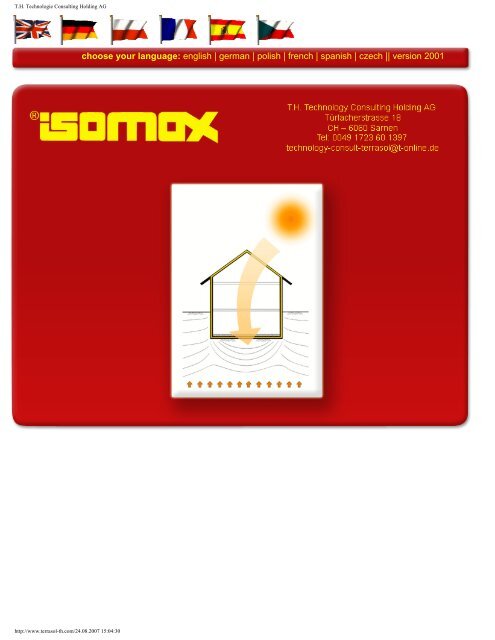
T.H. Technologie Consulting Holding AG - Isomax - Terrasol
T.H. Technologie Consulting Holding AG - Isomax - Terrasol
T.H. Technologie Consulting Holding AG - Isomax - Terrasol

You also want an ePaper? Increase the reach of your titles
YUMPU automatically turns print PDFs into web optimized ePapers that Google loves.
T.H. <strong>Technologie</strong> <strong>Consulting</strong> <strong>Holding</strong> <strong>AG</strong><br />
choose your language: english | german | polish | french | spanish | czech || version 2001<br />
http://www.terrasol-th.com/24.08.2007 15:04:30
T.H. <strong>Technologie</strong> <strong>Consulting</strong> <strong>Holding</strong> <strong>AG</strong><br />
Nowadays, about 40 % of all energy raw materials such as crude oil, natural gas and coal are being used<br />
for air-conditioning purposes, i.e. for heating and cooling of buildings - an unjustifiable luxury considering<br />
the fact that both ecologically friendly and economically useful alternatives are available.<br />
Despite a great variety of activities regarding the utilization of renewable energies the expenditure of<br />
primary energy for the manufacture of such systems and facilities as well as the initial costs for photovoltaic<br />
installations, solar collectors or heat pumps are definitely still too high as compared with the energy<br />
savings achievable.<br />
Presented in this essay will be a technology for the air conditioning of buildings utilizing the ground<br />
underneath the building as a storage medium and the solar energy as an energy carrier. This Terra-Sol<br />
building technology will require but minimum amounts of current and constitutes an economical alternative<br />
to conventional heating and air-conditioning systems both in regard to manufacturing and operating costs<br />
and in addition to the aspects of conservation of nature and environmental protection which are becoming<br />
more and more important for future generations.<br />
Terra-Sol-Building-Technology (pdf)<br />
For further information please contact us: Technology-Consult-<strong>Terrasol</strong>(at)t-online.de<br />
webdesign by artfulworx.com<br />
choose your language: english | german | polish | french | spanish | czech || version 2001<br />
http://www.terrasol-th.com/english.html24.08.2007 15:04:31
Air conditioning of buildings by near-surface geothermal<br />
energy<br />
Print from the Structural Engineering Yearbook 2005 issued<br />
by Verein Deutscher Ingenieure (VDI = Association of<br />
German Engineers)<br />
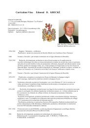
Dipl.-Ing. Edmond D. Krecké, Luxembourg<br />
Dr.-Ing. Klaus Kunkel, Duesseldorf<br />
1. Starting position<br />
Nowadays, about 40 % of all energy raw materials such as crude oil, natural gas and coal<br />
are being used for air-conditioning purposes, i.e. for heating and cooling of buildings – an<br />
unjustifiable luxury considering the fact that both ecologically friendly and economically useful<br />
alternatives are available.<br />
Despite a great variety of activities regarding the utilization of renewable energies the expenditure<br />
of primary energy for the manufacture of such systems and facilities as well as the<br />
initial costs for photo-voltaic installations, solar collectors or heat pumps are definitely still too<br />
high as compared with the energy savings achievable.<br />
Presented in this essay will be a technology for the air conditioning of buildings utilizing the<br />
ground underneath the building as a storage medium and the solar energy as an energy carrier.<br />
This Terra-Sol building technology will require but minimum amounts of current and constitutes<br />
an economical alternative to conventional heating and air-conditioning systems both<br />
in regard to manufacturing and operating costs and in addition to the aspects of conservation<br />
of nature and environmental protection which are becoming more and more important for<br />
future generations.<br />
2. Energy concept<br />
The basic idea of the Terra-Sol building technology consists in that solar energy is collected<br />
via the shell of a building adjoining the surrounding air, i.e. via roofing and walls and that this<br />
thermal energy is stored in the ground underneath the building and in case of need will be<br />
used for heating and cooling as well as for ventilation and aeration of a building. Collection of<br />
the solar energy, feeding thereof into the ground as well as tempering of walls and roofing<br />
will be effected via concealed plastic piping installed in building components and/or in the<br />
ground and filled with water (see Figure 1).<br />
1/12
Solar thermal gain<br />
Roof absorber piping<br />
Solar thermal gain: +15 to 75°C<br />
Roof absorber piping<br />
Solar thermal gain: +15 to 75°C<br />
AKK:<br />
Outside wall<br />
air<br />
conditioning<br />
and compensation<br />
system<br />
AKK:<br />
Outside wall<br />
air<br />
conditioning<br />
and compensation<br />
system<br />
Flow<br />
heater<br />
Cold water<br />
Distribution<br />
manifold<br />
Collector<br />
Room thermostat<br />
Cooling circuit I<br />
+7°C to +14°C<br />
for cooling outside<br />
walls in summer<br />
Boundary storage II<br />
+15°C to +24°C<br />
for heating outside<br />
walls<br />
Center storage III<br />
+25°C to +34°C<br />
for heating outside<br />
walls<br />
Core storage IV<br />
from +35°C<br />
For preheating of<br />
service water<br />
Center storage III<br />
+25°C to +34°C<br />
for heating outside<br />
walls<br />
Boundary storage II<br />
+15°C to +24°C<br />
for heating outside<br />
walls<br />
Cooling circuit I<br />
+7°C to +14°C<br />
for cooling outside<br />
walls in summer<br />
Geothermal gain<br />
Figure 1.<br />
Schematic diagram<br />
2/12
Via the roof absorber piping the solar energy is collected by heating the water contained in<br />
said piping up to a temperature of +80°C and fed into the ground underneath the sole plate<br />
by means of insulated piping. The ground underneath the sole plate is “diked“ laterally with<br />
insulation so as to serve as an efficient storage for the heat supplied. The storage is subdivided<br />
into different temperature zones by an appropriate control system. The core storage<br />
with temperatures above +35°C serves for preheating of the service water and the center<br />
and boundary storages with temperatures within the range of +15°C to +34°C serve for heating<br />
of the outside walls. A cooling circuit also conceivable outside of the building makes use<br />
of the relatively constant ground temperature of +7°C to +14°C and may be provided for cooling<br />
of the outside walls in summer.<br />
Apart from heating and/or cooling of walls and roofing, an additional aeration and ventilation<br />
of buildings by means of a “Pipe-in-Pipe” counterflow system is deemed useful. To this effect,<br />
the outgoing air from the rooms is dissipated in a larger-section pipe in one direction<br />
and the fresh air is supplied through a smaller pipe which is inserted in the larger-section<br />
pipe, in the opposite direction. In case of an adequate length of the two pipes heat exchange<br />
efficiencies in excess of 98% are achieved. The fresh air supplied through the pipe system is<br />
routed within the ground for heating and/or cooling as a function of outdoor temperatures.<br />
Figures 2 to 5 show examples of piping installations in the ground underneath the foundation<br />
slab as well as in and adjacent this sole plate and on the roof. Illustrated in Figure 6 is the<br />
erection of wall assembly units with integrated piping. Figure 7 shows the necessary control<br />
engineering restricted to two circulating pumps and several control valves.<br />
Figure 2.<br />
„Pipe-in-Pipe“ counterflow system<br />
3/12
Figure 3.<br />
Piping installation in a foundation slab prior to concrete work<br />
Figure 4.<br />
Cooling circuit piping installed adjacent a building<br />
Figure 5.<br />
Installation of solar absorber pipes on roof insulation boards<br />
4/12
Figure 6.<br />
Assembling of large-size wall elements with integrated piping<br />
Figure 7.<br />
Control engineering for a single-family home<br />
5/12
3. Energetic considerations<br />
3.1 Look at a wall cross-section<br />
Compared hereinafter will be the transmission heat loss per m² wall area for a wall with integrated<br />
piping, i.e. the so-called temperature barrier, and the same type of wall, however<br />
without temperature barrier. The temperature data specified in the EnEV (German Ordinance<br />
Regulating Energy Savings) applicable for locations in Germany have been taken as a basis<br />
for determination of the transmission heat losses. The outer walls involved consist of a concrete<br />
core of 15 cm thickness into which the temperature barrier is integrated, with heat insulation<br />
(PS 15, SE 040) of 7,5 cm thickness each on the inside and outside; see Figure 8.<br />
In case of a conventional wall design the transmission heat loss will be determined via the<br />
temperature gradient from the inside to the outside and by the U-value for the entire wall<br />
cross-section. With a building component with temperature barrier water preheated by the<br />
ground storage is passed through piping integrated in the wall cross-section and through the<br />
solid wall "embedded“ in heat insulation both on the inner and the outer sides. The wall<br />
cross-section will be heated to approx. +14°C to +18°C depending on the temperature of<br />
ground storage. The transmission temperature loss will thus be determined only by the temperature<br />
gradient from the inside (indoor temperature according to EnEV +19°C, for instance)<br />
to the temperature barrier. In principle, the outside insulation will no longer play a role in relafrom<br />
inside:<br />
Plastering mortar<br />
PS 15, SE 040<br />
Normal concrete 2400<br />
PS 15, SE 040<br />
WDV Final plaster coat<br />
(WDVS)<br />
U = 0,25 W/m²K<br />
Q T, inside<br />
Q T, outside<br />
Plastic piping filled with water<br />
= Temperature barriere (TB)<br />
Figure 8.<br />
Schematic diagram of the cross-section of outside walls involved<br />
6/12
tion to the transmission heat loss provided sufficient energy will be supplied by the ground<br />
storage for maintaining the wall temperature. Herein, attention should be paid that the ground<br />
storage will be supplied with thermal energy by insolation via the roof absorbers also in winter.<br />
Initially illustrated in Diagram 1 is the transmission heat loss of the entire outer wall (U-value<br />
= 0,25) without temperature barrier (TB). Considering the TB with a water temperature of<br />
+14°C and/or +18°C a distinction was made between<br />
• the inner wall portion (Q Ti ) taking into account the insulation of 7,5 cm thickness provided<br />
on the inside as well as the inner half of the concrete cross-section (up to the<br />
middle of temperature barrier TB = 7,5 cm) and<br />
• the outer wall portion (Q Ta ) comprising the outer half of the concrete cross-section<br />
and the insulation of 7,5 cm thickness provided on the outside.<br />
The following formula applies for determination of the transmission heat loss of wall without<br />
temperature barrier (TB):<br />
Q T ~ U · ∆t wherein ∆t = t i - t a<br />
For determination of the transmission heat losses of the inner and the outer wall portions the<br />
following formulas shall apply analogously (taking twice the U-value as a basis!)<br />
Q Ti ~ 2 U (t i - t B )<br />
Q Ta ~ 2 U (t B - t a )<br />
and the sum will be obtained as under:<br />
Q Ti + Q Ta ~ 2 U (t i - t a )<br />
Thus, the transmission heat loss of the wall with temperature barrier as a whole is double<br />
that of the wall without temperature barrier. The loss in the outer wall portion is covered by<br />
the ground storage and "free of charge". Logically, the loss in the inner wall portion needs to<br />
be minimized by reduction of the difference t i - t B . With the temperature of temperature barrier<br />
increasing, the transmission heat losses are "shifted" from the inner wall portion to the outer<br />
wall portion so that mainly energy from the ground storage and less the energy from the<br />
rooms is being consumed. Would the temperature of the temperature barrier equal the internal<br />
temperature, t i = t B , then there would be no loss in the inner wall portion.<br />
The direct comparison between the wall without temperature barrier and the wall with temperature<br />
barrier = +18°C shows that the transmission heat losses Q Ti are reduced from<br />
21,02 to 3,28 kWh/month per m² wall surface. This corresponds to a reduction of the heat<br />
demand for heating purposes by 81 % referred to the transmission heat losses of the outer<br />
wall.<br />
7/12
The temperatures of temperature barrier by months and for the entire heating period assumed<br />
have been taken as constant for reasons of this calculated comparison only. In practice,<br />
the temperature will continuously be adapted and optimized as a function of the desired<br />
indoor temperatures and the prevailing outdoor temperatures; this will apply both to heating<br />
and cooling of the buildings.<br />
Diagram 1. Transmission heat losses of an outside wall without temperature barrier, with<br />
temperature barrier = +14°C and with temperature barrier = +18°C<br />
Jan<br />
Feb<br />
Mar<br />
Apr<br />
May<br />
Sep<br />
Oct<br />
Nov<br />
Dec<br />
Sum<br />
without TB<br />
Q T<br />
kWh/Month per m²<br />
3,78<br />
3,09<br />
2,77<br />
1,71<br />
1,13<br />
0,83<br />
1,84<br />
2,57<br />
3,29<br />
21,02<br />
Q[kWh/Month] per m²<br />
4,00<br />
3,50<br />
3,00<br />
2,50<br />
2,00<br />
1,50<br />
1,00<br />
0,50<br />
0,00<br />
without Temperature barrier (TB)<br />
Jan<br />
Feb<br />
März<br />
Apr<br />
Mai<br />
Sep<br />
Okt<br />
Month<br />
Nov<br />
Dez<br />
with TB = 14°C<br />
Q Ti<br />
Q Ta<br />
kWh/Month per m²<br />
Jan 1,86 5,69<br />
Feb 1,68 4,50<br />
Mar 1,86 3,68<br />
Apr 1,80 1,62<br />
May 1,86 0,41<br />
Sep 1,66 0,00<br />
Oct 1,86 1,82<br />
Nov 1,80 3,35<br />
Dec 1,86 4,72<br />
Sum 16,24 25,80<br />
Q[kWh/Month] per m²<br />
6,00<br />
5,00<br />
4,00<br />
3,00<br />
2,00<br />
1,00<br />
0,00<br />
Jan<br />
Feb<br />
with TB = 14°C<br />
QTi<br />
QTa<br />
März<br />
Apr<br />
Mai<br />
Sep<br />
Month<br />
Okt<br />
Nov<br />
Dez<br />
with TB = 18°C<br />
Q Ti<br />
Q Ta<br />
kWh/Month per m²<br />
Jan 0,37 7,18<br />
Feb 0,34 5,85<br />
Mar 0,37 5,17<br />
Apr 0,36 3,06<br />
May 0,37 1,90<br />
Sep 0,36 1,30<br />
Oct 0,37 3,31<br />
Nov 0,36 4,79<br />
Dec 0,37 6,21<br />
Sum 3,28 38,76<br />
Q[kWh/Month] per m²<br />
8,00<br />
7,00<br />
6,00<br />
5,00<br />
4,00<br />
3,00<br />
2,00<br />
1,00<br />
0,00<br />
Jan<br />
Feb<br />
with TB = 18°C<br />
QTi<br />
QTa<br />
März<br />
Apr<br />
Mai<br />
Sep<br />
Month<br />
Okt<br />
Nov<br />
Dez<br />
8/12
3.2 Look at a single-family home<br />
When applying the considerations contained in the preceding section to a typical singlefamily<br />
home with basement, ground floor and garret storey with double pitch roof, the heat<br />
demand for heating purposes will be as shown in Diagram 2: Comparison of the conventional<br />
construction of a single-family home with the Terra-Sol building technology.<br />
The floor area of the building involved is 88 m² with the heated building volume amounting to<br />
797 m³. In both cases, the building components as well as the boundary conditions not influenced<br />
by the Terra-Sol building technology have been taken as identical as a basis for the<br />
calculation.<br />
Components: Roof<br />
U-value = 0,18 W/m²K<br />
Windows and doors U-value = 1,40 W/m²K<br />
Window area portion 17 %<br />
Thermal bridges<br />
U-value flat rate allowance 0,05 W/m²K<br />
The wall cross-section shown in 3.1 with U = 0,25 W/m²K as well as a free ventilation with an<br />
air change rate of 0,7 h -1 have been taken as a rating basis for the conventional construction.<br />
In the calculation by the Terra-Sol building technology and with a U-value of 0,50 W/m²K<br />
"half" the wall cross-section with a constant temperature barrier temperature of +18°C as well<br />
as the „Pipe-in-Pipe“ counterflow system with 96% - 98% heat recovery have been taken<br />
into consideration.<br />
Diagram 2 Comparison of heat demand for heating purposes<br />
Heat demand for heating of single-family house<br />
Qh [kWh]<br />
Qh [kWh]<br />
4.000<br />
3.500<br />
3.000<br />
2.500<br />
2.000<br />
1.500<br />
Outside walls without TB<br />
Outside walls with TB = 18°C, WRG<br />
1.000<br />
500<br />
0<br />
Jan<br />
Feb<br />
Mar<br />
Apr<br />
May<br />
Jun<br />
Jul<br />
Aug<br />
Sep<br />
Oct<br />
Nov<br />
Dec<br />
9/12
Based on the parameters specified above, the heat demand for heating purposes in a singlefamily<br />
home is calculated as follows:<br />
Outside walls without temperature barrier<br />
Outside walls with temperature barrier = +18° C, WRG<br />
Q h = 15.488 kWh/a<br />
Q h = 4.412 kWh/a<br />
Referred to the building useful area A N = 255 m²:<br />
Outside walls without temperature barrier<br />
Outside walls with temperature barrier = +18° C, WRG<br />
Q h = 60,7 kWh/m²a<br />
Q h = 17,3 kWh/m²a<br />
Setting out from this calculation there can be verified that the annual heat demand for heating<br />
of a building with Terra-Sol building technology consisting of temperature barrier and<br />
Pipe-in-Pipe counterflow system is approximately equal to that of a passive house standard<br />
with an annual heat demand for heating purposes of q h = 15 kWh/m².<br />
Upon a closer look at this calculation there will be noted that the major portion of the annual<br />
heat demand for heating purposes is attributable to the high U-value related to the quality of<br />
windows and doors. Accordingly, a heat demand for heating purposes reduced further to<br />
approx. 10 kWh/m² and less will be achievable when using windows and doors with a lower<br />
U-value and applying the Terra-Sol building technology and conventional insulation thicknesses.<br />
Herein, attention should be paid that the costs for a Terra-Sol building are lower than<br />
those of a building of conventional construction inter alia due to the fact that great insulation<br />
thicknesses and expensive windows with an extremely low U-value are not necessary.<br />
4. Examples and further development<br />
The Terra-Sol building technology has already been employed successfully in several countries<br />
such as Luxembourg, India and China. Diagram 3 shows a series of measurements<br />
over a period of four years with measurements of indoor temperature, outdoor temperature<br />
and the temperature prevailing in the ground storage of a single-family home. This building<br />
was constructed in Luxembourg in 2000 with a wall structure of light-weight concrete walls of<br />
15 cm thickness with 7,5 cm insulation each on the inside and on the outside and with a floor<br />
area of 175 m² in case of 1 ½ storeys. The theoretical consider-ations are confirmed in an<br />
impressive manner by the measuring values obtained.<br />
10/12
Diagram 3. Series of measurements for an exemplary building<br />
30,0<br />
Indoor temperature measuring point<br />
Temperature (°C)<br />
25,0<br />
20,0<br />
15,0<br />
1995<br />
1996<br />
1997<br />
1998<br />
20,0<br />
15,0<br />
10,0<br />
Jan<br />
Feb<br />
Mar<br />
Apr<br />
May<br />
Jun<br />
Jul<br />
Aug<br />
Sept<br />
Oct<br />
Nov<br />
Outdoor temperature measuring point (min)<br />
Dec<br />
1995<br />
1996<br />
1997<br />
1998<br />
Temperature (°C)<br />
5,0<br />
0,0<br />
-5,0<br />
Jan<br />
Feb<br />
Mar<br />
Apr<br />
May<br />
Jun<br />
Jul<br />
Aug<br />
Sep<br />
Oct<br />
Nov<br />
Dec<br />
-10,0<br />
-15,0<br />
-20,0<br />
30,0<br />
Measuring point, Center ground storage<br />
25,0<br />
Temperature °C<br />
20,0<br />
15,0<br />
1995<br />
1996<br />
1997<br />
1998<br />
10,0<br />
Jan<br />
Feb<br />
Mar<br />
Apr<br />
May<br />
Jun<br />
Jul<br />
Aug<br />
Sep<br />
Oct<br />
Nov<br />
Dec<br />
11/12
The insulation thicknesses normal for this type of single-family home will be optimized further<br />
with a view to the solar heat gains. In case of a current project an insulation (WLG 040) of<br />
5 cm each is provided on the inside and on the outside so that the absorption of solar energy<br />
via the outside walls is perceptible. In addition, a temperature barrier will also be installed<br />
within range of the roof areas which are relatively large as compared with the outside wall<br />
surfaces, so that comforting and controllable temperatures will be achievable via the temperature<br />
barrier also in rooms having no and/or very few outside walls.<br />
During construction of the building numerous measuring heads or probes will again be installed<br />
so as permit documentation by way of the measuring results as to how the reduced<br />
insulation thicknesses and the additional temperature barrier in the roofing influence the corresponding<br />
march of temperatures.<br />
5. Prospects<br />
The advantages of the two approved processes of solar engineering and utilization of geothermal<br />
heat are combined in an amazingly simple form by the utilization of solar energy in<br />
connection with the near-surface geothermal energy. Many examples already realized in all<br />
climatic zones verify the efficiency of this system extremely favourable in regard to both manufacturing<br />
and operating costs. In order to optimize and also to be able to "calculate" this<br />
building technology, further research and development are necessary. The objectives of further<br />
investigations are to gain control of the calculation of heat exchange processes and to<br />
optimize insulation thicknesses. The experience already gained, however, permits an ecofriendly<br />
and economical application of the Terra-Sol building technology already today.<br />
12/12
T.H. <strong>Technologie</strong> <strong>Consulting</strong> <strong>Holding</strong> <strong>AG</strong><br />
Heutzutage werden etwa 40 % aller Energierohstoffe wie Erdöl, Erdgas und Kohle zur Klimatisierung, d. h.<br />
zum Heizen und Kühlen von Gebäuden verwendet ein nicht vertretbarer Luxus, wenn man bedenkt, dass<br />
sowohl umweltschonende als auch wirtschaftlich sinnvolle Alternativen zur Verfügung stehen.<br />
Trotz vielfältiger Aktivitäten zur Nutzung erneuerbarer Energien ist der Primärenergieaufwand zur<br />
Herstellung solcher Systeme und Anlagen sowie die Anschaffungskosten für Fotovoltaiktechnik,<br />
Sonnenkollektoren oder für Wärmepumpen im Vergleich zu der erzielten Energieeinsparung noch<br />
entschieden zu hoch.<br />
In diesem Bericht wird die Terra-Sol-Gebäudetechnologie zur Klimatisierung von Gebäuden durch Nutzung<br />
des Bodenkörpers unterhalb des Gebäudes als Speichermedium und der Sonnenenergie als Energieträger<br />
vorgestellt. Diese <strong>Technologie</strong> benötigt nur geringe Mengen Strom und bietet neben dem für die zukünftigen<br />
Generationen immer wichtiger werdenden Schutz von Natur und Umwelt auch in wirtschaftlicher Hinsicht,<br />
bezogen sowohl auf die Herstellungskosten als auch auf die Betriebskosten, eine Alternative zu<br />
herkömmlichen Heizungs- und Klimaanlagen.<br />
Terra-Sol-Gebäudetechnologie (pdf)<br />
Weitere Informationen erhalten Sie unter: Technology-Consult-<strong>Terrasol</strong>(at)t-online.de<br />
webdesign by artfulworx.com<br />
choose your language: english | german | polish | french | spanish | czech || version 2001<br />
http://www.terrasol-th.com/german.html24.08.2007 15:04:42
T.H. Technology <strong>Consulting</strong> <strong>Holding</strong> <strong>AG</strong><br />
Türlacherstrasse 18 | CH - 6060 Sarnen | info@terrasol-th.com
T.H. Technology <strong>Consulting</strong> <strong>Holding</strong> <strong>AG</strong><br />
www.terrasol-TH.com<br />
INHALTSVERZEICHNIS<br />
Seiten<br />
1. Einleitung 2<br />
2. Nutzung oberflächennaher, sonnenunterstützter Erdwärme<br />
zur Energieeinsparung bei Gebäuden<br />
2<br />
3. Baugrunduntersuchung 9<br />
4. Grundlagen der energetischen Berechnunge 11<br />
4.1. Innen- und Außentemperaturen 12<br />
4.2. Außenbauteile 13<br />
4.2.1. Außenwände 14<br />
4.2.2. Dächer 16<br />
4.2.3. Fenster und große Glasflächen 17<br />
4.2.4. Bodenplatte 19<br />
4.3. Rohr-in-Rohr-Gegenstromanlage 20<br />
4.4. Interne Wärmegewinne 21<br />
5. Trinkwasservorerwärmung: Der Kernspeicher 21<br />
6. Energetische Berechnungen 22<br />
6.1. Transmissionswärmeverlust einer Außenwand 22<br />
6.2. Heizwärmebedarf eines Einfamilienhauses 26<br />
7. Temperaturmengen an einem ausgeführten Beispiel 27<br />
8. Ausblick 31<br />
Seite 1
T.H. Technology <strong>Consulting</strong> <strong>Holding</strong> <strong>AG</strong><br />
www.terrasol-TH.com<br />
1. Einleitung<br />
Heutzutage werden etwa 60 bis 70 % der uns zur Verfügung stehenden Energie<br />
zur Klimatisierung, d. h. zum Heizen und Kühlen von Gebäuden verwendet - ein<br />
nicht vertretbarer Luxus, wenn man bedenkt, dass so wohl umweltschonende als<br />
auch wirtschaftlich sinnvolle Alternativen zur Verfügung stehen.<br />
Trotz vielfältiger Aktivitäten zur Nutzung erneuerbarer Energien ist der Primärenergieaufwand<br />
zur Herstellung solcher Systeme und Anlagen sowie die Anschaffungskosten<br />
für Fotovoltaiktechnik, Sonnenkollektoren, Windmühlen oder für<br />
Wärmepumpen im Vergleich zu der erzielten Energieeinsparung noch entschieden<br />
zu hoch.<br />
In diesem Bericht wird die Terra-Sol-Gebäudetechnologie zur Klimatisierung von<br />
Gebäuden durch Nutzung des Bodenkörpers unterhalb des Gebäudes als Speichermedium<br />
und der Sonnenenergie als Energieträger vorgestellt. Diese <strong>Technologie</strong><br />
benötigt nur geringste Mengen Energie und bietet neben dem für die zukünftigen<br />
Generationen immer wichtiger werdenden Schutz von Natur und Umwelt<br />
auch in wirtschaftlicher Hinsicht, bezogen sowohl auf die Herstellungskosten als<br />
auch auf die Betriebskosten, eine Alternative zu herkömmlichen Heizungs- und<br />
Klimaanlagen.<br />
2. Nutzung oberflächennaher, sonnenunterstützter Erdwärme zur Energieeinsparung<br />
bei Gebäuden<br />
Der vom Erdinnern zur Erdoberfläche<br />
gerichtete kontinuierliche Wärmestrom<br />
wird auf 4 x 10 10 kW geschätzt; bezogen<br />
auf die Erdoberfläche sind dies ca. 0,7<br />
kWh je m² und Jahr. Für eine direkte<br />
Nutzung ist dieser Wert zu gering. Dafür<br />
kommen nur geothermische Anomalien<br />
in Frage: heiße Wässer, die in einem<br />
Aquifer eingeschlossen sind und außer<br />
in Geysiren meist keine natürliche<br />
Verbindung zur Erdoberfläche haben.<br />
Die thermische Nutzung des<br />
Untergrundes ist z.Zt. ein in Deutschland<br />
weitverbreitetes Thema; man<br />
unterscheidet dabei die Nutzung des<br />
Grundwassers mit Brunnenanlagen, die<br />
Nutzung des oberflächennahen<br />
Untergrundes über Erdwärmekollektoren<br />
Bild 2.1. Weinkeller<br />
Seite 2
T.H. Technology <strong>Consulting</strong> <strong>Holding</strong> <strong>AG</strong><br />
www.terrasol-TH.com<br />
oder Erdwärmesonden, wobei auch Gründungspfähle als Wärmeüberträger<br />
("Energiepfähle") verwendet werden. In allen diesen Fällen werden Wärmepumpen<br />
eingesetzt, um die für das Heizen der Gebäude erforderliche Vorlauftemperatur<br />
zu erreichen.<br />
Einen völlig anderen und wesentlich wirtschaftlicheren Weg beschritt der luxemburger<br />
Forscher und Entwickler, Dipl.-Ing. und Physiker Edmond D. Krecké, indem<br />
er die oberflächennahe Erdtemperatur, unterstützt durch Sonnenwärme, direkt<br />
nutzt.<br />
Es ist bekannt, dass in einer Tiefe von 3 m bis 4 m Sommer wie Winter eine von<br />
der Erdatmosphäre weitgehend unabhängige Temperatur von 9° bis 11° C<br />
herrscht. Manche nennen dies Weinkellertemperatur: Im Winter empfinden wir es<br />
als warm und im Sommer empfinden wir es als kühl. In das aufgehende Gebäude<br />
ist Heizenergie entsprechend der jeweiligen Temperaturdifferenzen zwischen innen<br />
und außen aufzuwenden (Bild 2.1.). Würden wir diese für praktische Zwecke<br />
in unermeßlichem Maße vorhandene Temperatur nutzen, indem wir alle Außenbauteile<br />
mit dieser Temperatur, von sagen wir 10° C, "versorgen", so würden auch<br />
sehr niedrige Außentemperaturen die Innentemperaturen nicht direkt beeinflussen<br />
können: Wir hätten uns sozusagen eine Temperaturbarriere geschaffen, und der<br />
Energieverbrauch des Gebäudes wäre nur von der Temperaturdifferenz der Innentemperatur<br />
zur Temperatur der Temperaturbarriere - wie in Bild 2.2. gezeigt -<br />
abhängig, gleichgültig wie tief die Außentemperatur sinkt.<br />
Wie können nun die Außenbauteile mit<br />
der Erdtemperatur versorgt werden?<br />
Im Kellerfußboden bzw. in ca. 3 m Tiefe<br />
werden Rohre verlegt, in denen Wasser<br />
zirkuliert. Das Wasser nimmt die<br />
Erdtemperatur auf, wird in die<br />
Außenbauteile gepumpt und fließt nach<br />
Wärmeabgabe von dort wieder zurück.<br />
Baut man ein Gebäude ohne Keller auf<br />
den Erdboden oder mit Keller in den Erdboden<br />
und dämmt die Bodenplatte<br />
oberseitig, staut sich der vom Erdinnern<br />
kommende Wärmestrom unter der<br />
Bodenplatte auf; die Temperaturen<br />
steigen dort an, bis sich ein<br />
Gleichgewicht mit dem seitlich des Gebäudes<br />
in die Erdatmosphäre entweichenden<br />
Wärmestrom einstellt. Diese<br />
Temperaturerhöhung tritt selbstverständ-<br />
Bild 2.2. Weinkeller mit Temperaturbarriere<br />
Seite 3
T.H. Technology <strong>Consulting</strong> <strong>Holding</strong> <strong>AG</strong><br />
www.terrasol-TH.com<br />
lich auch ein, wenn das Gebäude nicht beheizt wird. Der Temperaturanstieg ist<br />
u.a. von der Gründungstiefe und der Gebäudegrundriß fläche abhängig. Er beträgt<br />
i.M. 2 bis 4 Kelvin (K), so dass die Temperatur in der Temperaturbarriere ca. 12°<br />
C beträgt und für den Energieverbrauch die Temperat urdifferenz<br />
maßgebend ist (Bild 2.3.).<br />
∆t = 20° - 12° = 8 K<br />
Bild 2.3. Erdwärme unter einem<br />
gedämmten Gebäude<br />
Bild 2.4. Sonnenunterstützte Erdwärme<br />
Wünschenswert ist es, diese Temperaturdifferenz weiter zu verringern, d.h. die<br />
Temperatur in der Temperaturbarriere weiter zu erhöhen und zwar auf eine Temperatur,<br />
die für angenehme Innentemperaturen sorgt, ohne dass eine Energiezufuhr<br />
nötig ist, wobei selbstverständlich solare Zug ewinne, z.B. durch Fenster oder<br />
interne Zugewinne bei der Nutzung des Gebäudes Berücksichtigung finden.<br />
Hier kam der Physiker Krecké auf den Gedanken, eine weitere, unerschöpflich<br />
vorhandene, sehr leistungsfähige und ebenfalls kostenlose Energiequelle "anzuzapfen":<br />
Die Sonne (Bild 2.4.).<br />
Seite 4
T.H. Technology <strong>Consulting</strong> <strong>Holding</strong> <strong>AG</strong><br />
www.terrasol-TH.com<br />
Selbst in Deutschland weist die jährliche Sonneneinstrahlung eine Energie von<br />
i.M. 1000 kWh je m² und Jahr auf horizontale Flächen auf (Bild 2.5.).<br />
Nehmen wir einmal an, für die Versorgung der Temperaturbarriere benötigten wir<br />
eine Energiemenge von 10 kWh bezogen auf den m² Grundfläche und pro Jahr,<br />
so könnten wir mit der Einstrahlungsenergie in Deutschland 100 Geschoßflächen<br />
versorgen! Ein theoretischer Wert, von dem Verluste noch abgezogen werden<br />
müssen, der aber dennoch die Größenordnung zeigt. Hinzu kommt, dass insbesondere<br />
bei hohen Häusern nicht nur die horizontalen oder schrägen Dachflächen,<br />
sondern auch die vertikalen Wandflächen zur Absorption herangezogen<br />
werden können.<br />
Bild 2.5. Sonneneinstrahlung in Deutschland – mittlere Jahressumme in kWh/m²,<br />
Quelle: DWD<br />
Seite 5
T.H. Technology <strong>Consulting</strong> <strong>Holding</strong> <strong>AG</strong><br />
www.terrasol-TH.com<br />
Wir erkennen, dass mit der Sonne eine Energiequelle zur Verfügung steht, mit der<br />
wir Gebäude nahezu unentgeltlich klimatisieren können. Es ist lediglich eine Frage<br />
der Absorbtion sowie des Energietransports und der Energiespeicherung. Mit der<br />
Erde steht die Energiequelle zur Kühlung sowie das Medium zur Speicherung der<br />
Sonnenwärme zur Verfügung. Wir nennen diese Technik Terra-Sol-Technik.<br />
Unter der Dacheindeckung, genauer gesagt zwischen Dacheindeckung und Wärmedämmung,<br />
werden die Absorberleitungen - Kunststof fröhrchen, wie die zuvor<br />
beschriebenen Temperaturbarriereleitungen - verlegt ; in den Außenwänden - sofern<br />
dort Absorberleitungen erforderlich sind - werden sie im Außenputz verlegt.<br />
Das in den Röhrchen enthaltene Wasser erwärmt sich im Sommer bei Sonnenschein<br />
und entsprechenden Außentemperaturen auf bis zu 75° C, im Winter selbst<br />
bei Minusgraden und Sonnenschein auf nutzbare 20° bis 25° C.<br />
In gedämmten Rohren wird das erwärmte Wasser in die Bodenplatte, und zwar in<br />
die Kernzone bei hohen Temperaturen oder in die Mittel- und Randzonen bei<br />
niedrigeren Temperaturen geführt (Bild 2.6.). Von der oberseitig gedämmten Bodenplatte<br />
wandert die Wärme ins Erdreich, wo sie gespeichert wird. Zur Verringerung<br />
der seitlichen Wärmeverluste - also zur Verringerung der Wärme, die in die<br />
Erdatmosphäre entweicht - wird entlang des Gebäudegrundrisses eine entsprechende<br />
Dämmung im Erdreich eingebaut. Im Bedarfsfall wird mit der im Erdreich<br />
gespeicherten Wärme das in den Rohrleitungen der Bodenplatte enthaltene Wasser<br />
erwärmt, in die Temperaturbarriere der Außenhülle geführt, wo es abkühlt und<br />
anschließend wieder der Bodenplatte zugeführt wird. Durch eine Vielzahl von<br />
Messungen an mit dem Terra-Sol-Prinzip ausgestattet en Gebäuden wurde festgestellt,<br />
dass die Temperatur des in der Bodenplatte in Rohren enthaltenen Wassers,<br />
bevor es in die Außenhülle gepumpt wird, 18° bis 20° C aufweist; dabei beträgt<br />
die Temperatur des Erdreiches unter der Bodenplatte ca. 20° bis 22° C.<br />
Höhere Temperaturen werden im Erdspeicher nicht erreicht, auch wenn besonders<br />
hohe Absorberleistungen zuvor erzielt werden: Anstelle einer Temperaturerhöhung<br />
vergrößert sich das Volumen des Erdspeichers.<br />
Durch jahrzehntelange Erfahrungen wurde festgestellt, dass bei Nutzung der gesamten<br />
Dachflächen eines Gebäudes als Absorberflächen weit mehr Wärmeenergie<br />
als erforderlich zur Verfügung steht.<br />
In den meisten Fällen wird in der Kernzone eines Gebäudes ein allseits gedämmter<br />
sogenannter Kernspeicher angelegt, der im Gegensatz zu dem übrigen<br />
Erdspeicher mit Schlauchleitungen durchsetzt ist. Hierdurch werden Wassertemperaturen<br />
bis zu 35° C erreicht, die zur Trinkwasservorerwärmung genutzt werden.<br />
Seite 6
T.H. Technology <strong>Consulting</strong> <strong>Holding</strong> <strong>AG</strong><br />
www.terrasol-TH.com<br />
Bild 2.6. Leitungsprinzip<br />
Seite 7
T.H. Technology <strong>Consulting</strong> <strong>Holding</strong> <strong>AG</strong><br />
www.terrasol-TH.com<br />
Die Schlauchleitungen der Temperaturbarriere, die im Winter zur Erwärmung der<br />
Gebäudehülle genutzt werden, werden im Sommer zur Kühlung genutzt. Bis vor<br />
kurzem wurden dazu gesonderte, im Erdreich außerhalb des Gebäudegrundrisses<br />
und damit außerhalb des Erdspeichers sich befindende Schlauchleitungen mit<br />
entsprechend niedrigen Wassertemperaturen verlegt. Hier wurde nun eine Vereinfachung<br />
erreicht: Zur Kühlung im Sommer werden die Schlauchleitungen aus<br />
den Randzonen des Erdspeichers genutzt, da - wie schon erwähnt - hier keine<br />
höheren Temperaturen als 20°bis 22° C erzielt werden. Zu den Einspareffekten<br />
durch erheblich geringere Schlauchleitungslängen kommt der Vorteil, dass im<br />
Sommer, im Kühlungsfall, wenn die Wassertemperatur in der Temperaturbarriere<br />
erhöht wird, diese erhöhte Temperatur wieder abgegeben und gespeichert werden<br />
kann.<br />
Die Klimatisierung, d.h. Heizen und Kühlen eines Gebäudes über die Temperaturbarriere<br />
in den Außenbauteilen stellt bezüglich der Temperaturregelung ein vergleichsweise<br />
träges System dar. Deshalb wird eine flinke Komponente hinzugefügt<br />
in Form einer speziellen, ebenfalls patentierten Lüftung, der Rohr-in-Rohr-<br />
Gegenstromanlage. In einem äußeren, größeren Rohr wird die Abluft und in einem<br />
kleineren, inneren Rohr wird die Zuluft geführt. Das Rohrsystem wird unter<br />
der Bodenplatte im Erdspeicher verlegt. Durch die beiden ineinander liegenden<br />
Rohre, die an der Baustelle aus dünnen Edelstahlblechen gewickelt werden, werden<br />
Wärmerückgewinnungsgrade von bis zu 98 % erreicht.<br />
Mit Hilfe des beschriebenen Systems werden extrem niedrige Energieverbräuche<br />
erzielt, sie liegen zwischen 5 und 12 kWh/m²/a. Zum Vergleich seien folgende<br />
Werte genannt:<br />
- Passivhäuser 15 - 25 kWh/m²/a<br />
- Niedrigenergiehäuser 40 - 60 kWh/m²/a<br />
- Gebäude nach der Wärmeschutzverordnung 1995 90 bis 100 kWh/m²/a<br />
- Deutscher Gebäudebestand i.M. 200 kWh/m²/a<br />
- Verglaste Bürogebäude 500 kWh/m²/a und mehr<br />
Die extrem niedrigen Energieverbräuche von Gebäuden mit Terra-Sol-Technik<br />
werden dabei nicht mit erhöhten Herstellkosten erkauft; das Gegenteil ist der Fall.<br />
Im Vergleich zu üblichen Passivhäusern ergeben sich folgende Vorteile:<br />
- überaus schlanke und wirtschaftliche Außenwände<br />
- preiswerter als herkömmliche Heizungs- und Lüftungstechnik<br />
- vergleichsweise geringe Außenwanddämmungen, damit Nutzflächengewinn<br />
- gleichmäßige Temperatur in allen Außenbauteilen, dadurch kein Kondensat<br />
und keine Schimmelbildung und damit<br />
- gesundes, natürliches Wohlfühlklima<br />
- sehr hoher Beitrag zum Umweltschutz, da keine CO -Emissionen<br />
2<br />
Seite 8
T.H. Technology <strong>Consulting</strong> <strong>Holding</strong> <strong>AG</strong><br />
www.terrasol-TH.com<br />
- praktisch uneingeschränktes Nutzerverhalten, da kostenlose Energiequelle im<br />
Überfluß<br />
- keine hochgedämmten, teuren Fenster erforderlich.<br />
Wir haben bisher die Temperaturbarriere in massiven Bauteilen behandelt, wobei<br />
der Temperaturträger, mit dem die Außenhülle klimatisiert wird, aus dem Medium<br />
Wasser besteht.<br />
Für große Fensterflächen mit relativ hohen Wärmeverlusten im Winter und hohen<br />
Energieeinträgen im Sommer wurde kürzlich analog zur Temperaturbarriere in<br />
Außenwänden mittels des Temperaturträgers Wasser einer Temperaturbarriere<br />
mit dem Temperaturträgermedium Luft patentiert, siehe Abschnitt 4.2.3, so dass<br />
mit dieser revolutionären und dennoch extrem wirtschaftlichen Entwicklung aus<br />
Luxemburg künftig auch große Glasfassaden energiesparend und umweltfreundlich<br />
geplant und gebaut werden können.<br />
3. Baugrunduntersuchung<br />
Die <strong>Terrasol</strong>-<strong>Technologie</strong> der <strong>Isomax</strong> Castellum Investment <strong>AG</strong> nutzt das natürlich<br />
vorhandene Erdreich unter den Gründungskörpern der Gebäude als Wärmespeicher.<br />
Folglich ist der Baugrund nicht nur auf seine Belastbarkeit hin zu untersuchen,<br />
sondern ebenso hinsichtlich seiner Wärmeleitfähigkeit und seiner Wärmespeicherkapazität.<br />
Andere künstliche Wärmespeicher sind aus wirtschaftlichen<br />
Gründen nur in Sonderfällen herzurichten. Grundsätzlich darf festgehalten werden,<br />
dass feuchte Böden eine höhere Wärmespeicherkapazität als trockene Böden<br />
aufweisen. Wasser besitzt die höchste Wärmespeicherkapazität. Nachfolgend<br />
sind einige Werte aus der Richtlinie 4640 des Vereins Deutscher Ingenieure angegeben.<br />
Für andere Böden können dort weitere Werte entnommen werden.<br />
Seite 9
T.H. Technology <strong>Consulting</strong> <strong>Holding</strong> <strong>AG</strong><br />
www.terrasol-TH.com<br />
Tabelle 3.1. Beispiele für Wärmeleitfähigkeit und volumenbezogene spezifische Wärmekapazität<br />
des Untergrundes, bei ca. 20°C<br />
(Auszug aus VDI-Richtlinie 4640, Blatt 1, Tabelle 1)<br />
Gestein<br />
Dichte ρ<br />
10³ kg/m³<br />
Wärmeleitfähigkeit<br />
W/(m ⋅ K)<br />
(typischer Rechenwert)<br />
λ<br />
volumenbezogene<br />
spezifische<br />
Wärmekapazität ρ ⋅ c p<br />
kWh/(m³ K)<br />
Magmatische Gesteine:<br />
Basalt 2,6 – 3,2 1,7 0,64 – 0,72<br />
Metamorphe Gesteine:<br />
Marmor 2,5 – 2,8 2,1 0,56<br />
Sedimentgesteine:<br />
Kalkstein 2,6 – 2,7 2,8 0,58 – 0,67<br />
Sandstein 2,2 – 2,7 2,3 0,44 – 0,78<br />
Lockergesteine:<br />
Kies, trocken 2,7 – 2,8 0,4 0,39 – 0,44<br />
Kies, wassergesättigt ca. 2,7 1,8 ca. 0,67<br />
Sand, trocken 2,6 – 2,7 0,4<br />
Sand, wassergesättigt 2,6 – 2,7 2,4 0,61 – 0,81<br />
Ton/Schluff, trocken n.a. 0,5 0,42 – 0,44<br />
Ton/Schluff, wassergesätt. n.a. 1,7 0,44 – 0,94<br />
Andere Stoffe:<br />
Beton ca. 2,0 1,6 ca. 0,5<br />
Luft (0 – 20°C, trocken) 0,0012 0,02 0,00033<br />
Stahl 7,8 60 0,87<br />
Wasser (+ 10°C) 0,999 0,59 1,15<br />
Bei den Baugrunduntersuchungen ist besonderes Augenmerk darauf zu richten,<br />
ob im Bereich des künftigen Wärmespeichers Grundwasser vorhanden ist bzw.<br />
auftreten kann. Wenn Grundwasser auftreten kann, sind die Schwankungen und<br />
ihre Wiederkehrwahrscheinlichkeit festzustellen.<br />
Bei strömendem Grundwasser ist zu unterscheiden zwischen vertikaler und horizontaler<br />
Strömung. Vertikale Strömung ist unbedenklich, da die Lage der im Wasser<br />
gespeicherten Wärmeenergie nur angehoben oder abgesenkt wird. Bei horizontaler<br />
Strömung des Grundwassers ist die Fließgeschwindigkeit durch Versuche<br />
festzustellen. Horizontale Fließgeschwindigkeiten bis zu wenigen Metern pro<br />
Jahr sind unbedenklich. Bei höheren Fließgeschwindigkeiten sind diese in Abhängigkeit<br />
von der Größe des Baufeldes durch nachfolgend beschriebene Maßnahmen<br />
zu reduzieren.<br />
Seite 10
T.H. Technology <strong>Consulting</strong> <strong>Holding</strong> <strong>AG</strong><br />
www.terrasol-TH.com<br />
Bei einzelnen kleineren Baumaßnahmen wird das Erdreich ca. 2,5 – 3,0 m tiefer<br />
ausgehoben als für den Gründungskörper selbst erforderlich. In die vertiefte Baugrube<br />
wird eine widerstandsfähige perforierte Kunststofffolie ausgelegt, deren<br />
Perforation so bemessen ist, dass sich die gewünschte reduzierte horizontale<br />
Fließgeschwindigkeit des Grundwassers einstellt. Die vertiefte Baugrube ist anschließend<br />
zu verfüllen und tragfähig zu verdichten, wobei als Verfüllmaterial<br />
i.d.R. der natürlich anstehende Boden wieder verwendet werden kann. Anstelle<br />
der perforierten Folie kann auch eine Lage Bodenmaterial mit geringer Wasserdurchlässigkeit<br />
eingebaut werden. Dies ist ebenfalls mit dem Baugrundgutachter<br />
abzustimmen.<br />
Bei größeren Baumaßnahmen empfiehlt es sich, das Baufeld mit Rüttelstopfpfählen<br />
zu umgeben. Dabei werden Bohrungen in bestimmten horizontalen Abständen<br />
abgeteuft und anschließend mit einem gut verdichtbaren Bodenmaterial verfüllt.<br />
Bei der lagenweisen Verfüllung wird das Bodenmaterial entsprechend verdichtet.<br />
Während dieser Verdichtungsarbeit wird auch der natürliche Boden zwischen den<br />
einzelnen Pfählen entsprechend verdichtet und die Durchlässigkeit gegenüber<br />
dem Grundwasser reduziert. Alle das Grundwasser betreffenden Maßnahmen<br />
sind mit der zuständigen Wasserbehörde abzustimmen.<br />
Auch bei größeren Horizontalbewegungen des erwärmten Grundwassers ist positiv<br />
zu bemerken, dass das Luftporenvolumen oberhalb der grundwasserführenden<br />
Schichten eine gute Dämmschicht darstellt. Dies verhindert ein Entweichen der<br />
gespeicherten Wärme außerhalb des Gebäudegrundrisses in die Erdatmosphäre<br />
wirksam.<br />
4. Grundlagen der energetischen Berechnungen<br />
Um die energetischen Berechnungen für ein Gebäude durchzuführen, d.h. um den<br />
Wärme- bzw. den Kühlbedarf zu ermitteln, bedarf es vorab einiger Festlegungen,<br />
z.B. der am Standort vorherrschenden Außentemperaturen, der gewünschten<br />
oder geforderten Innentemperaturen, des Konstruktionsaufbaus der Außenbauteile,<br />
der Nutzung des Gebäudes etc.<br />
Seite 11
T.H. Technology <strong>Consulting</strong> <strong>Holding</strong> <strong>AG</strong><br />
www.terrasol-TH.com<br />
4.1. Innen- und Außentemperaturen<br />
Die Außentemperaturen sind in Deutschland als monatliche Mittelwerte in DIN V<br />
4108-6 festgelegt und in Tabelle 4.1. wiedergegeben. Sollte es in einem Land keine<br />
Festlegung geben, können die monatlichen Mittelwerte bei Wetterstationen für<br />
die letzten drei bis fünf Jahre erfragt werden. Aus den monatlichen Mittelwerten<br />
der letzten Jahre sind die monatlichen Mittelwerte zu berechnen, die der energetischen<br />
Berechnung zugrunde zu legen sind. Sicherheitszu- oder abschläge sind zu<br />
berücksichtigen oder eventuelle „Ausreißer“, wie das sonnenreiche Jahr 2003 in<br />
Mitteleuropa, sind bei der Mittelwertfindung nicht zu berücksichtigen. Die mittlere<br />
Außentemperatur über das gesamte Jahr, in Deutschland z.B. 8,9°C, geht in die<br />
energetische Berechnung nicht direkt ein.<br />
Tabelle 4.1. Durchschnittliche Monatstemperaturen<br />
in Deutschland nach DIN V 4108-6<br />
t A t I ? T<br />
[°C] [°C] [K]<br />
Jan -1,3 19,0 20,3<br />
Feb 0,6 19,0 18,4<br />
März 4,1 19,0 14,9<br />
Apr 9,5 19,0 9,5<br />
Mai 12,9 19,0 6,1<br />
Jun 15,7 19,0 3,3<br />
Jul 18,0 19,0 1,0<br />
Aug 18,3 19,0 0,7<br />
Sep 14,4 19,0 4,6<br />
Okt 9,1 19,0 9,9<br />
Nov 4,7 19,0 14,3<br />
Dez 1,3 19,0 17,7<br />
8,9<br />
t A : Mittlere Außentemperatur<br />
t I : Norm - Innentemperatur<br />
? T : Temperaturdifferenz<br />
Bezüglich der Innentemperaturen ist nicht die maximal gewünschte Innentemperatur<br />
eines oder mehrerer Räume, sondern die mittlere Temperatur für das gesamte<br />
Gebäude anzusetzen. In Deutschland sind dies 19°C gemäß DIN V 4108-6.<br />
Seite 12
T.H. Technology <strong>Consulting</strong> <strong>Holding</strong> <strong>AG</strong><br />
www.terrasol-TH.com<br />
Hinsichtlich der im Rahmen der energetischen Berechnung anzusetzenden Temperatur<br />
der Temperaturbarriere ist folgendes zu berücksichtigen: Aus dutzenden<br />
von Messungen unterschiedlicher Projekte in verschiedenen Klimazonen ist bekannt,<br />
dass das vom Erdreich erwärmte Wasser in den Schlauchleitungen der<br />
Bodenplatte vor Zuführung in die Temperaturbarriere der Außenbauteile eine<br />
Temperatur von 20°C bis 21°C aufweist, wenn zuvor vom Frühjahr bis zum<br />
Herbst, also über ein komplettes Sommerhalbjahr, Sonnenwärme absorbiert und<br />
im Erdspeicher gespeichert wurde. Unter Berücksichtigung eines geringfügigen<br />
Leitungsverlustes darf daher die Temperatur der Temperaturbarriere bei der energetischen<br />
Berechnung mit mindestens 18°C angesetzt werden.<br />
Bei Inbetriebnahme eines Gebäudes, z.B. im Oktober, wenn zuvor also noch keine<br />
Wärmespeicherung erfolgen konnte, ist für die Temperatur in der Temperaturbarriere<br />
10°C anzusetzen. Zwischen diesen Werten kann entsprechend gemittelt<br />
werden. Damit ist der Jahresheizwärmebedarf für verschiedene Wärmespeicherungsgrade<br />
ermittelbar. Wenn also davon auszugehen ist, dass in der Anfangsphase<br />
ein geringer Wärmespeicherungsgrad vorliegt, so ist in dieser Anfangsphase<br />
der zusätzliche Heizwärmebedarf durch besondere Maßnahmen zu decken.<br />
Hier kommen Heizregister an den Auslässen der Lüftungszuleitungen oder das<br />
Aufheizen des Temperaturbarrierenwassers in Frage. Sobald genügend Wärme<br />
im Erdspeicher gespeichert wurde, kann auf diese Sondermaßnahmen verzichtet<br />
werden.<br />
Interessant ist in diesem Zusammenhang die aufgrund jahrelanger Erfahrung gemachte<br />
Feststellung, dass selbst nach intensiver Wärmespeicherung im Erdreich<br />
die Temperaturen unterhalb der Bodenplatte, außer selbstverständlich im Kernspeicher,<br />
niemals über 20°C bis 22°C liegen. Es ist deshalb möglich, mit denselben<br />
Leitungen der Bodenplatte die Temperaturbarriere der Außenhülle bei hohen<br />
Außentemperaturen im Sommer zu versorgen und die Kühllast des Gebäudes und<br />
somit die Innentemperaturen zu reduzieren. Sind die Kühllasten des Gebäudes<br />
höher als gewöhnlich, kann ein gesonderter Kühlkreislauf mit Schlauchleitungen<br />
außerhalb des Gebäudegrundrisses mit im Erdreich verlegten Leitungen angeordnet<br />
werden.<br />
Besondere Anforderungen an die Temperaturen spezieller Räume, z.B. werden in<br />
Deutschland 24°C in Bädern gefordert, oder Anforderungen an Kühlräume sind<br />
gesondert und raumweise zu behandeln, sind also nicht Gegenstand der energetischen<br />
Berechnung des Gebäudes.<br />
4.2. Außenbauteile<br />
Die Wärmeverluste eines Gebäudes in den Monaten, in denen die Außentemperaturen<br />
niedriger sind als die geforderten Innentemperaturen, und die Wärmeeinträge<br />
in ein Gebäude in den Monaten, in denen die Außentemperaturen höher<br />
Seite 13
T.H. Technology <strong>Consulting</strong> <strong>Holding</strong> <strong>AG</strong><br />
www.terrasol-TH.com<br />
sind als die geforderten Innentemperaturen, erfolgen durch Transmission über die<br />
Außenbauteile (Außenwände, auch erdberührt; Dächer; Fenster).<br />
Bei Fenstern kommt die Wärmeübertragung durch Strahlung hinzu.<br />
4.2.1. Außenwände<br />
Die Temperaturbarriere kann grundsätzlich in allen Arten von Außenwandkonstruktionen<br />
bei Neubauten eingebaut werden, aber auch bei bestehenden Gebäuden<br />
kann die Temperaturbarriere problemlos angewandt werden.<br />
Bei Neubauten mit Betonwänden (Normal- oder Leichtbeton; bewehrte oder unbewehrte<br />
Wände) empfiehlt es sich, die Temperaturbarriere in die Wand zu legen<br />
(Bild 4.2.).<br />
Bei Mauerwerkswänden und bei Wänden bestehender Bauten wird die Temperaturbarriere<br />
auf der Außenfläche der Wand befestigt und anschließend eingeputzt.<br />
Der Putz ist als ebene Fläche für die anschließend aufzubringende Wärmedämmung<br />
erforderlich, aber auch zur besseren Temperaturleitung in Richtung der<br />
Wandebene (Bild 4.3.).<br />
Eine besonders wirtschaftliche Außenwandkonstruktion besteht in der Herstellung<br />
der patentierten Biopor-Leichtbetonwände mit beidseitigen Polystyrol-<br />
Hartschaumplatten als Schalung in Dicken von jeweils 5 oder 7,5 cm.<br />
Bei Holzhäusern wird die Temperaturbarriere wegen der erforderlichen Wärmeleitung<br />
in einen Estrich oder eine Vergußmasse eingebettet (Bild 4.4.).<br />
Bild 4.2. Aussenwand aus Beton mit<br />
Temperaturbarriere (TB)<br />
Bild 4.3. Aussenwand aus Mauerwerk<br />
mit TB<br />
Bild 4.4. Aussenwand eines Holzhauses<br />
mit TB<br />
Seite 14
T.H. Technology <strong>Consulting</strong> <strong>Holding</strong> <strong>AG</strong><br />
www.terrasol-TH.com<br />
Die Temperaturbarriere (TB)<br />
auf oder in den<br />
Außenwänden<br />
wird<br />
feldweise angeordnet, wobei<br />
die einzelnen Felder den<br />
innenliegenden Räumen<br />
entsprechen. Hiermit ist eine<br />
raumweise Regelung der<br />
Temperaturbarriere möglich<br />
(Bild 4.5.).<br />
Zur Begrenzung der<br />
Reibungsverluste und damit<br />
der Leistungskapazität der<br />
Pumpen ist die Länge der<br />
einzelnen Schlauchleitungen<br />
auf maximal 100 bis 120 m<br />
zu begrenzen. Bei der Verlegung<br />
sind Kreuzungspunkte<br />
zu vermeiden.<br />
Bild 4.5. Raumweise Anordnung der TB<br />
Bild 4.6. zeigt zwei grundsätzliche Möglichkeiten der feldweisen Leitungsführung.<br />
Die in Bild 4.6 b dargestellte Leitungsführung hat den – geringen – Vorteil, dass<br />
sich die unterschiedlichen Temperaturen des Vorlaufs und des Rücklaufs ausgleichen.<br />
Diese Verlegungsart erfordert aber etwas mehr Aufwand bei der Planung<br />
und der Ausführung. Besondere Aufmerksamkeit ist der Leitungsführung im Bereich<br />
der Fenster und Türöffnungen zu widmen. Die Abstände der Leitungen untereinander<br />
betragen ca. 20 bis 25 cm.<br />
Sofern die Dachflächen nicht ausreichen, um die erforderlichen Absorberleitungen<br />
unterzubringen, können diese auch in den Außenwänden angeordnet werden. Die<br />
Absorberleitungen werden dann in einem mit entsprechender Dicke aufzubringenden<br />
Außenputz verlegt.<br />
Bild 4.6.a Leitungsführung in<br />
Aussenwänden<br />
Bild 4.6.b alternative Leitungsführung<br />
in Aussenwänden<br />
Seite 15
T.H. Technology <strong>Consulting</strong> <strong>Holding</strong> <strong>AG</strong><br />
www.terrasol-TH.com<br />
4.2.2. Dächer<br />
Im wesentlichen wird zwischen Kaltdach und Warmdach unterschieden. Bei Kaltdächern,<br />
häufig bei Steildächern anzutreffen, werden die Absorberleitungen unter<br />
der Dacheindeckung, also im Luftraum zwischen Dacheindeckung und Wärmedämmung,<br />
verlegt. Ob auf eine Temperaturbarriere unterhalb der Wärmedämmung<br />
verzichtet werden kann, hängt im Einzelfall vom Verhältnis der Wandfläche<br />
zu den Dachflächen in den Dachgeschoß-Räumen ab. Bei einem verhältnismäßig<br />
hohen Wandflächenanteil, z.B. Giebelwandflächen mit Temperaturbarriere, kann<br />
auf eine Temperaturbarriere in den Dachflächen verzichtet werden.<br />
Bei einem verhältnismäßig geringen Wandflächenanteil im Dachgeschoß, also mit<br />
einem ebenfalls geringen Anteil an Wandflächen mit Temperaturbarriere, muß eine<br />
Temperaturbarriere in den Dachflächen angeordnet werden.<br />
Eine besonders wirtschaftliche und patentierte Bauweise besteht darin, Dachelemente<br />
als vorgefertigte Teile mit integrierter Temperaturbarriere und Absorberfeld<br />
herzustellen. Bild 4.7. zeigt ein solches vorgefertigtes Dachelement mit einer<br />
Breite von ca. 1,20 m, das im Werk hergestellt und auf der Baustelle verlegt wird.<br />
Bei der Ausbildung des Daches als Warmdach wird die Temperaturbarriere wie<br />
bei einer Außenwand entweder im Beton oder auf der Außenfläche des Dachtragwerks<br />
mit einem Estrich zur Einbettung der Leitungen verlegt. Darauf wird die<br />
Wärmedämmung aufgebracht, und oberhalb der Wärmedämmung werden die Absorberleitungen<br />
im Estrich, der als Träger der Dachdichtung dient, gemäß Bild 4.8.<br />
verlegt.<br />
Bild 4.7. Sparrendach (Kaltdach) mit<br />
Absorber und TB<br />
Bild 4.8. Flachdach (Warmdach) mit<br />
Absorber und TB<br />
Seite 16
T.H. Technology <strong>Consulting</strong> <strong>Holding</strong> <strong>AG</strong><br />
www.terrasol-TH.com<br />
4.2.3. Fenster und große Glasflächen<br />
Aufgrund der im Erdreich gespeicherten kostenlosen Sonnenwärme stellt die <strong>Terrasol</strong>-<strong>Technologie</strong><br />
der <strong>Isomax</strong> Castellum Investment <strong>AG</strong> keine besonderen Anforderungen<br />
an die Wärmedämmeigenschaften der verglasten Flächen, meist reichen<br />
U-Werte zwischen 1,1 und 1,3 W/(m² K) aus. Besser dämmende Fenster<br />
oder gar Dreifachverglasungen sind nicht erforderlich. Gegenüber den üblichen<br />
Passivhäusern ist auch dies ein wesentlicher wirtschaftlicher Vorteil. Die Festlegung<br />
der Fensterqualität erfolgt gemäß der energetischen Berechnung.<br />
Die solaren Zugewinne durch die verglasten Fensterflächen hängen von der Ausrichtung<br />
des Gebäudes ab; hierauf braucht aber nicht besonders geachtet zu werden,<br />
da sowohl für das Heizen als auch für das Kühlen des Gebäudes ausreichend<br />
kostenlose Energie zur Verfügung steht. Somit können bei der Ausrichtung<br />
des Gebäudes Parameter wie Einbindung in die Umgebung und Nutzung des Gebäudes<br />
Priorität vor den solaren Zugewinnen haben.<br />
Bei sehr großen Fensterflächen sei auf eine weitere patentierte Neuentwicklung<br />
hingewiesen: Die Temperaturbarriere aus Luft.<br />
Diese Technik wurde zum ersten Mal vor vier Jahren bei mehreren baugleichen<br />
Bürogebäuden in Chengdu, China, eingesetzt. In den verglasten zweigeschossigen<br />
Atrien wurde auf eine Höhe von ca. 6 m lediglich eine 12 mm dicke Glasscheibe<br />
eingebaut. Wegen der hohen erforderlichen Kühllast bei Sonneneinstrahlung<br />
und hohen Außentemperaturen ist hier der Sommer kritischer zu sehen<br />
als der Winter. Am Fußpunkt der Scheibe wird 18° bis 19° warme bzw. kühle Luft,<br />
die durch das Erdreich herangeführt wird, eingeblasen. Durch Erwärmung entlang<br />
der Scheiben erhöht sich die Lufttemperatur über die Höhe von ca. 6 m um ca. 5<br />
bis 6 K und wird am oberen Scheibenende abgezogen. Die erwärmte Luft wird in<br />
Lüftungskanälen durch das Erdreich geführt, wo sie die Wärme wieder abgibt und<br />
erneut zum Scheibenfußpunkt geführt. Vor der Glasscheibe wurde durch diese<br />
Maßnahme eine wirksame Temperaturbarriere aus Luftgeschaffen. Elektrischer<br />
Strom und damit Energie wird lediglich zum Transport der Luft benötigt, nicht aber<br />
zum Heizen und Kühlen der Gebäude.<br />
In der zugehörigen Patentschrift sind verschiedene Ausführungsmöglichkeiten<br />
detailliert beschrieben. Eine erhöhte Luftkammerwirkung vor der äußeren Glasscheibe<br />
wird durch die Anordnung einer zweiten inneren Glasscheibe im Abstand<br />
von ca. 6 bis 8 cm erreicht.<br />
Seite 17
T.H. Technology <strong>Consulting</strong> <strong>Holding</strong> <strong>AG</strong><br />
www.terrasol-TH.com<br />
Mit der beschriebenen Technik wird zum ersten Mal ein Null-Energie-Gebäude bei<br />
vollständig verglasten Fassadenflächen möglich. Hier sei daran erinnert, dass<br />
gemäß einer Definition des Deutschen Fraunhofer-Instituts Gebäude mit einem<br />
Energiebedarf von weniger als 15 kWh/m²/a als Null-Energie-Gebäude bezeichnet<br />
werden dürfen.<br />
Bild 4.9. zeigt in einer Systemskizze das patentierte Verfahren der Temperaturbarriere<br />
aus Luft.<br />
Bild 4.9. Temperaturbarriere aus Luft<br />
Seite 18
T.H. Technology <strong>Consulting</strong> <strong>Holding</strong> <strong>AG</strong><br />
www.terrasol-TH.com<br />
4.2.4. Bodenplatte<br />
Die Bodenplatte wird in<br />
Stahlbeton ausgeführt. Ihre<br />
Dicke wird gemäß dem<br />
statischen Nachweis<br />
festgelegt. Bei niedrigen<br />
Gebäuden ist eine Dicke<br />
von 20 cm meist<br />
ausreichend (Bild 4.10.).<br />
Die vom Dach und<br />
eventuell auch von den<br />
Außenwänden kommenden<br />
Absorberleitungen werden<br />
in einem Kollektor<br />
zusammengeführt und je<br />
nach Wassertemperatur in<br />
unterschiedliche Bereiche<br />
der Bodenplatte geleitet:<br />
Bild 4.10. Bodenplatte mit TB<br />
- Wasser mit Temperaturen höher als 35° wird in den Zentralbereich geführt. Ist<br />
ein Kernspeicher zur Trinkwasservorerwärmung vorgesehen, wird er im Zentralbereich<br />
angeordnet.<br />
- Wasser mit Temperaturen zwischen 25° und 35° wird in den Mittelbereich eingeleitet.<br />
- Wasser mit Temperaturen bis 25°wird in den Randbereich eingeleitet.<br />
Die verschiedenen Bereiche sind im Bild 2.6. gekennzeichnet.<br />
Die Leitungsführung in der Bodenplatte ist in Plänen darzustellen, damit auf der<br />
Baustelle nach eindeutigen Vorgaben gearbeitet werden kann. Die Bodenplatte<br />
wird oberseitig gedämmt, damit die Wärme gänzlich in den Erdspeicher abwandert.<br />
Bei Altbauten wird es manchmal nicht möglich bzw. nicht wirtschaftlich sein, die<br />
Sonnenenergie in bzw. unter der Bodenplatte einzuspeisen. In einem solchen Fall<br />
können die Leitungen neben dem bestehenden Gebäude im Erdreich verlegt werden.<br />
Sie sind seitlich und nach oben zu dämmen.<br />
Seite 19
T.H. Technology <strong>Consulting</strong> <strong>Holding</strong> <strong>AG</strong><br />
www.terrasol-TH.com<br />
4.3. Rohr-in-Rohr Gegenstromanlage<br />
Da die Temperaturbarriere in den Außenbauteilen bezüglich der Temperaturregelung<br />
recht träge ist, wird eine „flinke“ Komponente in Form einer ebenfalls patentierten<br />
Lüftungsanlage, der sogenannten Rohr-in-Rohr Gegenstromanlage,<br />
hinzugefügt. In einem äußeren, größeren Rohr wird die Abluft und in einem kleineren,<br />
inneren Rohr wird die Zuluft geführt (Bild 4.11.).<br />
Bild 4.11. Rohr-in-Rohr Gegenstromanlage<br />
Das Rohrsystem wird von der oberirdischen Nutzfläche kommend durch die Bodenplatte<br />
in den Erdspeicher geführt und dort unterhalb der Bodenplatte, vorzugsweise<br />
im Randspeicher auf einer Länge von 40 bis 45 m verlegt, um dann<br />
außerhalb des Gebäudes Zuluft aufzunehmen und Abluft abzugeben. Die Rohre<br />
bestehen aus einem aus 0,12 bis 0,15 mm dicken gewickelten Edelstahlblech, das<br />
außen zur besseren Wärmeübertragung Stege aufweist. In dem die Frischluft führenden<br />
Rohr kann an der Rohrwandung der Taupunkt unterschritten werden und<br />
somit Kondensat entstehen. Die Rohre sind deshalb im Erdreich mit 0,5 % Gefälle<br />
zu verlegen und es ist dafür Sorge zu tragen, dass das Kondensat abgeführt werden<br />
kann.<br />
Berechnungen für die Auslegung und Dimensionierung der Lüftungsrohre können<br />
mit Hilfe dynamischer Simulationsprogramme durchgeführt werden. Aufgrund der<br />
großen Bandbreite der Randbedingungen wie Bodenverhältnisse, klimatische<br />
Verhältnisse etc. sind große Abweichungen in den Ergebnissen zu erwarten. Als<br />
Eingangsparameter für solche Berechnungen sind u.a. die Dichte des Bodens, die<br />
spezifische Wärmekapazität, die Wärmeleitfähigkeit und der Wassergehalt des<br />
Bodens zu ermitteln. Die Strömungsgeschwindigkeiten sollten zwischen 1,0 m/sec<br />
und 1,4 m/sec liegen. Bei Luftwechselraten zwischen 0,4 und 0,8/h ergeben sich<br />
bei üblichen Wohnungsgrößen Luftvolumenströme bis zu 500 m³/h.<br />
Seite 20
T.H. Technology <strong>Consulting</strong> <strong>Holding</strong> <strong>AG</strong><br />
www.terrasol-TH.com<br />
4.4. Interne Wärmegewinne<br />
Interne Wärmegewinne werden durch elektrische Geräte, Beleuchtungen und<br />
Personen erzielt. Grundsätzlich muß entschieden werden, ob eine differenzierte<br />
Ermittlung oder eine überschlägige Ermittlung der Wärmegewinne, bezogen auf<br />
eine Bezugsgröße wie z.B. die Nutzfläche, Berücksichtigung finden soll. Wenn eine<br />
differenzierte Betrachtung über elektrische Geräte, Beleuchtungen und Personen<br />
sinnvoll erscheint, dann sollte diese bezogen auf die jeweiligen Jahreszeiten<br />
und Monate erfolgen. Als Anhaltswert für eine überschlägige Ermittlung der Wärmegewinne<br />
kann dienen, dass im Rahmen der Deutschen Energieeinsparverordnung<br />
bei Wohngebäuden 5 W je m² Gebäudenutzfläche anzusetzen sind. Bei einem<br />
Wohnhaus mit 150 m² Wohnnutzfläche sind dies 6.570 kWh/a.<br />
5. Trinkwasservorerwärmung: Der Kernspeicher<br />
Es ist empfehlenswert, für die Brauchwasservorerwärmung einen gesonderten<br />
Speicher, den sogenannten Kernspeicher, unter der Bodenplatte einzubauen. Es<br />
handelt sich hierbei um einen allseits mit 10 cm druckfestem Dämmmaterial versehenen<br />
Erdkörper, in den Schlauchleitungen mit Wassertemperaturen oberhalb<br />
35°C geleitet wird. Das Volumen des Kernspeichers sollte ca. 20 bis 30 m³ pro<br />
Wohneinheit betragen.<br />
Der Kernspeicher ist in Bereichen mit geringer statischer Belastung, also möglichst<br />
nicht unter tragenden Wänden anzuordnen. Wenn dies nicht möglich ist, ist<br />
das Erdreich im Kernspeicher entsprechend zu verdichten. Dies ist vom Tragwerksplaner<br />
entsprechend zu berücksichtigen.<br />
Anders als im Mittel- und im Randspeicher werden zur Erwärmung des Kernspeichers<br />
die Warmwasser führenden Leitungen direkt in den Speicher geführt. Pro<br />
m³ Erdreich sollten mindestens 3 lfdm Warmwasserleitung vorhanden sein. Eine<br />
zweckmäßige und wirtschaftliche Ausführungsart zeigt Bild 5.1. Hier wird in den<br />
allseits gedämmten Bereich des Kernspeichern eine Bewehrungsmatte gestellt,<br />
an die die Schlauchleitungen geknüpft werden. Anschließend wird der Kernspeicherbereich<br />
mit Erdreich verfüllt.<br />
Wenn der Kernspeicher in einem Bereich mit statischer Belastung angeordnet und<br />
das Erdreich im Kernspeicher verdichtet werden muß, empfiehlt es sich, ein oder<br />
mehrere Fertigteilwandelemente von ca. 10 bis 12 cm Dicke, in dem alle<br />
Schlauchleitungen enthalten sind, einzustellen.<br />
Seite 21
T.H. Technology <strong>Consulting</strong> <strong>Holding</strong> <strong>AG</strong><br />
www.terrasol-TH.com<br />
Bild 5.1. Kernspeicher unter Bodenplatte<br />
6. Energetische Berechnungen<br />
6.1. Transmissionswärmeverlust einer Außenwand<br />
Im folgenden wird der Transmissionswärmeverlust je m² Wandfläche für eine<br />
Wand mit integrierter Rohrleitung, der sogenannten Temperaturbarriere, und einer<br />
Wand mit demselben Aufbau, jedoch ohne Temperaturbarriere, verglichen. Als<br />
Grundlage für die Ermittlung der Transmissionswärmeverluste wurden die in der<br />
Energieeinsparverordnung für den Standort Deutschland vorgegebenen Temperaturdaten<br />
verwendet. Die betrachteten Außenwände bestehen aus einem 15 cm<br />
dicken Betonkern, in den die Temperaturbarriere integriert ist, mit innen- und außenseitiger<br />
jeweils 7,5 cm dicker Wärmedämmung (PS 15, SE 040), (Bild 6.1).<br />
Bei einem konventionellen Wandaufbau wird der Transmissionswärmeverlust über<br />
das Temperaturgefälle von innen nach außen und durch den U-Wert des gesamten<br />
Wandquerschnitts bestimmt. Bei einem Bauteil mit Temperaturbarriere wird<br />
die massive Wand, die sowohl innen als auch außen in Wärmedämmung "eingepackt"<br />
ist, vom Wasser in den Rohrleitungen im Wandquerschnitt durchströmt,<br />
welches vorher vom Erdspeicher erwärmt bzw. gekühlt wurde. Der Wandquerschnitt<br />
wird je nach Temperatur des Erdspeichers erwärmt oder gekühlt. Der<br />
Transmissionswärmeverlust wird somit nur durch das Temperaturgefälle von innen<br />
zur Temperaturbarriere bestimmt. Die Außendämmung spielt für den Transmissionswärmeverlust<br />
im Prinzip keine Rolle mehr, vorausgesetzt, der Erdspeicher<br />
liefert genügend Energie zum Aufrechterhalten der Wandtemperatur. Hierbei<br />
Seite 22
T.H. Technology <strong>Consulting</strong> <strong>Holding</strong> <strong>AG</strong><br />
www.terrasol-TH.com<br />
ist zu beachten, dass der Erdspeicher bei Sonneneinstrahlung auch im Winter<br />
über die Dachabsorber mit Wärmeenergie versorgt wird.<br />
Bild 6.1. Prinzipdarstellung des betrachteten<br />
Außenwandquerschnitts<br />
Im Diagramm 6.1 wird zunächst der Transmissionswärmeverlust der gesamten<br />
Außenwand (U-Wert = 0,25) ohne Temperaturbarriere (TB) dargestellt. Bei Berücksichtigung<br />
der TB mit einer Wassertemperatur von 14°C bzw. 18°C wurde<br />
unterschieden zwischen dem<br />
• inneren Wandteil (Q Ti ), welcher die innen angeordnete 7,5 cm dicke Dämmung,<br />
sowie die innere Hälfte des Betonquerschnitts berücksichtigt und dem<br />
• äußeren Wandteil (Q Ta ), welcher die äußere Hälfte des Betonquerschnitts und<br />
die außen angeordnete 7,5 cm dicke Dämmung berücksichtigt.<br />
Für den Transmissionswärmeverlust der Wand ohne TB gilt<br />
Q T ~ U · ∆t<br />
mit ∆t = t i - t a<br />
Für die Transmissionswärmeverluste des inneren und äußeren Wandteils gilt<br />
sinngemäß (hierbei ist jeweils der doppelte U-Wert einzusetzen!)<br />
Seite 23
T.H. Technology <strong>Consulting</strong> <strong>Holding</strong> <strong>AG</strong><br />
www.terrasol-TH.com<br />
und für die Summe ergibt sich<br />
Q Ti ~ 2 U (t i - t B )<br />
Q Ta ~ 2 U (t B - t a )<br />
Q Ti + Q Ta ~ 2 U (t i - t a )<br />
Die Wand mit TB weist also insgesamt den doppelten rechnerischen Transmissionswärmeverlust<br />
gegenüber der Wand ohne TB auf, was aber nur auf den ersten<br />
Blick wie ein Nachteil erscheint, denn der Verlust des äußeren Wandteils wird aus<br />
dem Erdspeicher gespeist und ist "gratis". Der Verlust des inneren Wandteils ist -<br />
logischerweise - durch Reduzierung der Differenz t i - t B zu minimieren. Mit steigender<br />
Temperatur der Temperaturbarriere werden die Transmissionswärmeverluste<br />
vom inneren Wandteil auf den äußeren Wandteil "verlagert", so dass vornehmlich<br />
die Energie aus dem Erdspeicher und weniger die Energie aus den<br />
Räumen verbraucht wird. Wäre die Temperatur der Temperaturbarriere gleich der<br />
Innentemperatur, t i = t B , entstünde kein Verlust im inneren Wandteil.<br />
Der direkte Vergleich zwischen der Wand ohne TB und der Wand mit TB = 18°C<br />
zeigt, dass die Transmissionswärmeverluste Q Ti von 21,02 auf 3,28 kWh/Monat<br />
pro m² Wandfläche reduziert werden.<br />
Das entspricht einer Verringerung des Heizwärmebedarfs in Bezug auf die<br />
Transmissionswärmeverluste der Außenwand um 81 %.<br />
Nur aus Gründen des rechnerischen Vergleichs wurden die Temperaturen der<br />
Temperaturbarriere monatsweise und über die gesamte angenommene Heizperiode<br />
hinweg als konstant angesetzt. In den praktischen Fällen wird sie entsprechend<br />
den gewünschten Innentemperaturen und den vorherrschenden Außentemperaturen<br />
ständig angepaßt und optimiert; dies gilt sowohl für das Heizen als<br />
auch für das Kühlen der Gebäude.<br />
Seite 24
T.H. Technology <strong>Consulting</strong> <strong>Holding</strong> <strong>AG</strong><br />
www.terrasol-TH.com<br />
Diagramm 6.1.Transmissionswärmeverluste einer Außenwand ohne TB, mit TB = 14°C<br />
und mit TB = 18°C<br />
Jan<br />
Feb<br />
März<br />
Apr<br />
Mai<br />
Sep<br />
Okt<br />
Nov<br />
Dez<br />
Summe<br />
ohne TB<br />
Q T<br />
kWh/Monat pro m²<br />
3,78<br />
3,09<br />
2,77<br />
1,71<br />
1,13<br />
0,83<br />
1,84<br />
2,57<br />
3,29<br />
21,02<br />
m²<br />
pro<br />
Q[kWh/Monat]<br />
4,00<br />
3,00<br />
2,00<br />
1,00<br />
0,00<br />
ohne Temperaturbarriere (TB)<br />
J an<br />
F eb<br />
März<br />
Apr<br />
Mai<br />
S ep<br />
Monat<br />
Okt<br />
Nov<br />
Dez<br />
mit TB = 14°C<br />
Q Ti<br />
Q Ta<br />
kWh/Monat pro m²<br />
Jan 1,86 5,69<br />
Feb 1,68 4,50<br />
März 1,86 3,68<br />
Apr 1,80 1,62<br />
Mai 1,86 0,41<br />
Sep 1,66 0,00<br />
Okt 1,86 1,82<br />
Nov 1,80 3,35<br />
Dez 1,86 4,72<br />
Summe 16,24 25,80<br />
m²<br />
pro<br />
Q[kWh/Monat]<br />
6,00<br />
5,00<br />
4,00<br />
3,00<br />
2,00<br />
1,00<br />
0,00<br />
J an<br />
F eb<br />
mit TB = 14°C<br />
QTi<br />
QTa<br />
März<br />
Apr<br />
Mai<br />
S ep<br />
Monat<br />
Okt<br />
Nov<br />
Dez<br />
mit TB = 18°C<br />
Q Ti<br />
Q Ta<br />
kWh/Monat pro m²<br />
Jan 0,37 7,18<br />
Feb 0,34 5,85<br />
März 0,37 5,17<br />
Apr 0,36 3,06<br />
Mai 0,37 1,90<br />
Sep 0,36 1,30<br />
Okt 0,37 3,31<br />
Nov 0,36 4,79<br />
Dez 0,37 6,21<br />
Summe 3,28 38,76<br />
m²<br />
pro<br />
Q[kWh/Monat]<br />
8,00<br />
7,00<br />
6,00<br />
5,00<br />
4,00<br />
3,00<br />
2,00<br />
1,00<br />
0,00<br />
J an<br />
F eb<br />
mit TB = 18°C<br />
QTi<br />
QTa<br />
März<br />
Apr<br />
Mai<br />
S ep<br />
Monat<br />
Okt<br />
Nov<br />
Dez<br />
Seite 25
T.H. Technology <strong>Consulting</strong> <strong>Holding</strong> <strong>AG</strong><br />
www.terrasol-TH.com<br />
6.2. Heizwärmebedarf eines Einfamilienhauses<br />
Wendet man die im vorhergehenden Abschnitt erläuterten Überlegungen auf ein<br />
typisches Einfamilienhaus mit Keller-, Erd- und Dachgeschoß mit Satteldach an,<br />
stellt sich der Heizwärmebedarf wie im Diagramm 6.2. gezeigt dar: Vergleich der<br />
konventionellen Bauweise eines Einfamilienhauses mit Terra-Sol-<br />
Gebäudetechnologie.<br />
Die Grundfläche des betrachteten Gebäudes beträgt 88 m² und das beheizte Gebäudevolumen<br />
797 m³. Als Grundlage für die Berechnung wurden in beiden Fällen<br />
die Bauteile sowie die Randbedingungen, die nicht durch die Terra-Sol-<br />
Gebäudetechnologie beeinflußt werden, als identisch vorausgesetzt.<br />
Bauteile: Dach<br />
Fenster u. Türen<br />
U-Wert = 0,18 W/m²K<br />
U-Wert = 1,40 W/m²K<br />
Fensterflächenanteil 17 %<br />
Wärmebrücken pauschaler U-Wert-Zuschlag 0,05 W/m²K<br />
Für die Bemessung bei konventioneller Bauweise wurde der unter 6.1. betrachtete<br />
Wandquerschnitt mit U = 0,25 W/m²K sowie eine freie Lüftung mit einer Luftwechselrate<br />
von 0,7 h -1 angesetzt.<br />
Bei der Berechnung mit der Terra-Sol-Gebäudetechnologie wurde bei einem<br />
U-Wert von 0,50 W/m²K der "halbe" Wandquerschnitt mit einer konstanten Temperatur-Barrieren-Temperatur<br />
von 18°C sowie die „Rohr-in-Rohr“ - Gegenstromanlage<br />
mit 90% Wärmerückgewinnung berücksichtigt.<br />
Diagramm 6.2. Heizwärmebedarf im Vergleich<br />
[kWh]<br />
4.000<br />
3.500<br />
3.000<br />
2.500<br />
2.000<br />
1.500<br />
1.000<br />
Heizwärmebedarf des Einfamilienhauses<br />
Qh [kWh]<br />
500<br />
0<br />
J an<br />
F eb<br />
März<br />
Apr<br />
Mai<br />
J un<br />
J ul<br />
Aug<br />
S ep<br />
Okt<br />
Nov<br />
Dez<br />
Qh<br />
Außenwände ohne TB<br />
Außenwände mit TB = 18°C, WRG<br />
Seite 26
T.H. Technology <strong>Consulting</strong> <strong>Holding</strong> <strong>AG</strong><br />
www.terrasol-TH.com<br />
Der Heizwärmebedarf des Einfamilienhauses stellt sich auf der Grundlage der zuvor<br />
aufgeführten Parameter rechnerisch wie folgt ein:<br />
Außenwände ohne TB<br />
Q h = 15.488 kWh/a<br />
Außenwände mit TB = 18° C, WRG Q h = 4.412 kWh/a<br />
Auf die Gebäudenutzfläche A<br />
Außenwände ohne TB<br />
N = 255 m² bezogen:<br />
q h = 60,7 kWh/m²/a<br />
Außenwände mit TB = 18° C, WRG q h = 17,3 kWh/m²/a<br />
Durch diese Berechnung kann belegt werden, dass der Jahres-Heizwärmebedarf<br />
bei einem Gebäude mit Terra-Sol-Gebäudetechnologie, bestehend aus Temperaturbarriere<br />
und Rohr-in-Rohr-Gegenstromanlage, etwa einem Passivhaus-<br />
Standard mit einem Jahresheizwärmebedarf q h = 15 kWh/m²/a gleich kommt.<br />
Bei einer näheren Betrachtung der Berechnung fällt auf, dass der größte Anteil<br />
des Jahresheizwärmebedarfs aufgrund des hohen U-Wertes auf die Fenster- und<br />
Türqualität zurückzuführen ist.<br />
Somit kann bei Einsatz von Fenstern und Türen mit niedrigerem U-Wert, unter<br />
Anwendung der Terra-Sol-Gebäudetechnologie und üblicher Dämmstoffdicken,<br />
ein nochmals geringerer Heizwärmebedarf von ca. 10 kWh/m²/a und<br />
darunter erreicht werden.<br />
Dabei ist zu beachten, dass die Herstellungskosten eines Terra-Sol-Gebäudes<br />
unter denen eines nach konventioneller Bauweise errichteten Gebäudes liegen,<br />
u.a. deshalb, weil große Dämmdicken und teure Fenster mit sehr niedrigem U-<br />
Wert nicht erforderlich sind.<br />
7. Temperaturmessungen an einem ausgeführten Beispiel<br />
Die <strong>Isomax</strong> / Terra-Sol-Gebäudetechnologie ist bereits in vielen Ländern, u.a. in<br />
Deutschland, Luxemburg, Belgien, Frankreich, Schweiz, USA, Malaysia, Dschibuti,<br />
Venezuela, Indien (hier sei die Erdbebensicherheit der Betonfertigteile erwähnt)<br />
und China, mit Erfolg angewandt worden. Diagramm 6.3. zeigt eine Meßreihe<br />
über vier Jahre mit Messungen der Innentemperatur, der Außentemperatur und<br />
der Temperatur im Erdspeicher an einem ausgeführten Einfamilien-Wohnhaus.<br />
Dieses Gebäude wurde im Jahr 1995 in Luxemburg mit einem Wandaufbau von<br />
15 cm dicken Leichtbeton-Wänden mit innen und außen jeweils 7,5 cm dicker<br />
Dämmung und einer Wohnfläche von 175 m² bei 1 1/2-geschossiger Bauweise errichtet.<br />
Die Meßwerte bestätigen eindrucksvoll die theoretischen Überlegungen.<br />
Seite 27
T.H. Technology <strong>Consulting</strong> <strong>Holding</strong> <strong>AG</strong><br />
www.terrasol-TH.com<br />
Diagramm 6.3. Meßreihen an einem ausgeführten Beispiel<br />
30,0<br />
Meßpunkt Innentem peratur<br />
(°C )<br />
T emperatur<br />
25,0<br />
20,0<br />
15,0<br />
1995<br />
1996<br />
1997<br />
1998<br />
J<br />
anuar<br />
F ebruar<br />
März<br />
A pril<br />
Mai<br />
J<br />
uni<br />
J<br />
uli<br />
A ugus t<br />
S eptember<br />
Oktober<br />
November<br />
Dezember<br />
2 0 ,0<br />
1 5 ,0<br />
1 0 ,0<br />
M e ß p u n k t A u s s e n t e m p e r a t u r ( m in d )<br />
1 9 9 5<br />
1 9 9 6<br />
1 9 9 7<br />
1 9 9 8<br />
(°C )<br />
5 ,0<br />
T emperatut<br />
0 ,0<br />
-5 ,0<br />
-1 0 ,0<br />
anuar<br />
J<br />
F ebruar<br />
März<br />
A pril<br />
Mai<br />
uni<br />
J<br />
uli<br />
J<br />
A ugus t<br />
S eptember<br />
Oktober<br />
November<br />
Dezember<br />
-1 5 ,0<br />
-2 0 ,0<br />
3 0 ,0<br />
M e ß p u n k t Z e n tru m E rd s p e ic h e r<br />
2 5 ,0<br />
T emperatur<br />
2 0 ,0<br />
1 5 ,0<br />
1 0 ,0<br />
J anuar<br />
F ebruar<br />
März<br />
April<br />
Mai<br />
J uni<br />
J uli<br />
Augus t<br />
S eptember<br />
Oktober<br />
November<br />
Dezember<br />
°C<br />
1 9 95<br />
1 9 96<br />
1 9 97<br />
1 9 98<br />
Seite 28
T.H. Technology <strong>Consulting</strong> <strong>Holding</strong> <strong>AG</strong><br />
www.terrasol-TH.com<br />
Die bei diesem Einfamilien – Wohnhaus im Bereich des üblichen liegenden<br />
Dämmmdicken werden in Hinblick auf die solaren Wärmegewinne weiterhin optimiert.<br />
Bei einem aktuellen Projekt werden innen und außen jeweils 5 cm Dämmung<br />
(WLG 040) angeordnet, so dass sich die Absorption der Sonnenenergie über die<br />
Außenwände bemerkbar macht. Zusätzlich wird auch in dem Bereich der - im Verhältnis<br />
zu den Außenwandflächen relativ großen -Dachflächen eine Temperaturbarriere<br />
eingebaut, so dass auch Räume, die keine bzw. sehr wenige Außenwände<br />
aufweisen, angenehme und regulierbare Temperaturen über die Temperaturbarriere<br />
erreichen.<br />
Bei der Errichtung des Gebäudes werden wieder zahlreiche Meßsonden installiert,<br />
so dass anhand der Meßergebnisse dokumentiert werden kann, wie sich die verringerten<br />
Dämmdicken und die zusätzliche Temperaturbarriere im Dach auf die jeweiligen<br />
Temperaturverläufe auswirken.<br />
Die Bilder 7.1. bis 7.5. zeigen unterschiedliche Bauphasen verschiedener ISOMAX-<br />
Nullenergiehäuser, Bild 7.6. zeigt die notwendige Regelungstechnik, die sich auf<br />
zwei Umwälzpumpen und einige Regelungsventile beschränkt.<br />
Bild 7.1. Verlegung der Rohrleitungen in einer<br />
Bodenplatte vor dem Betonieren<br />
Bild 7.2. Verlegte Leitungen des Kühlkreislaufes<br />
neben einem Gebäude<br />
Seite 29
T.H. Technology <strong>Consulting</strong> <strong>Holding</strong> <strong>AG</strong><br />
www.terrasol-TH.com<br />
Bild 7.3. Verlegung der Solarabsorberrohre<br />
auf Dachdämmplatten<br />
Bild 7.4. Montage von Großwandelementen<br />
mit integrierten Rohrleitungen<br />
Bild 7.5.. „Rohr-in-Rohr“ –<br />
Gegenstromanlage<br />
Bild 7.6. Regelungstechnik für ein<br />
Einfamilienwohnhaus<br />
Seite 30
T.H. Technology <strong>Consulting</strong> <strong>Holding</strong> <strong>AG</strong><br />
www.terrasol-TH.com<br />
8. Ausblick<br />
Die Nutzung der Solarenergie in Verbindung mit der oberflächennahen geothermischen<br />
Energie verbindet in verblüffend einfacher Form die Vorteile der beiden bewährten<br />
Verfahren Solartechnik und Erdwämenutzung. Viele bereits ausgeführte<br />
Beispiele in allen Klimazonen belegen die Effizienz dieses Systems, welches sowohl<br />
hinsichtlich der Herstellungs- als auch der Betriebskosten sehr kostengünstig<br />
ist. Die <strong>Isomax</strong> / Terra-Sol-Gebäudetechnologie kann durch künftige Forschungen<br />
und Entwicklungen weiter optimiert, die Energieverbräuche – die heute schon unter<br />
10 kWh/m²/a liegen - und die Herstellkosten weiter erheblich reduziert werden. Die<br />
bereits gemachten Erfahrungen ermöglichen jedoch schon heute den umweltschonenden,<br />
wirtschaftlichen und technisch einwandfreien Einsatz der <strong>Isomax</strong> / Terra-<br />
Sol-Gebäudetechnologie.<br />
Seite 31
T.H. <strong>Technologie</strong> <strong>Consulting</strong> <strong>Holding</strong> <strong>AG</strong><br />
W dzisiejszych czasach stosuje si• oko•o 40 % materia•ów grzewczych takich jak olej, gaz i w•giel do<br />
ogrzewania jak i klimatyzowania budynków. Jest to du•y luksus, wiedz•c o tym, •e istniej• inne mo•liwo•ci<br />
wykorzystania energii, które s• o wiele ta•sze jak równierz ekologiczne.<br />
Nawet przy mo•liwo•ci zastosowania odzyskanej energii do klimatyzacji i ogrzewania budynków, koszty<br />
produkcji i zakup kolektorów s•onecznych jak i równierz tzw. „ciep•ej pompy s• w stosunku do odzysku<br />
energii za wysokie.<br />
Nast•puj•cy artyku• opisuje nowoczesn• technologi• „Terra-Sol", s•u••c• do ekonomicznego i ekologicznego<br />
ogrzewania i ch•odzenia budynku. Polega ona na kumulowaniu ciep•a s•onecznego pod budynkiem.<br />
Zastosowanie tej technologi wymaga bardzo ma•ej ilo•ci pr•du co jest bardzo pozytywne dla ekologii<br />
•rodowiska jak i ekonomicznej eksploatacji.<br />
Terra-Sol-Building-Technology (pdf)<br />
Jesli ma Panstwo pytania, to prosimy o email: Technology-Consult-<strong>Terrasol</strong>(at)t-online.de<br />
webdesign by artfulworx.com<br />
choose your language: english | german | polish | french | spanish | czech || version 2001<br />
http://www.terrasol-th.com/polish.html24.08.2007 15:06:37
T.H. <strong>Technologie</strong> <strong>Consulting</strong> <strong>Holding</strong> <strong>AG</strong><br />
UN SYSTEME REVOLUTIONNAIRE DANS LE BATIMENT<br />
La maison d’isolation énergétique ®ISOMAX a été construitepar la firme ISOMAX CASTELLUM INVESTMENT <strong>AG</strong>.,<br />
L-6315 BEAUFORT,à des fins de recherche en technologie solaire géothermique.<br />
Montage rapide<br />
La maison de recherche solaire-géothermique de ®ISOMAX a été érigée en 2 jours, c.à.d., le montage de la<br />
toiture a eu lieu le 2e jour.<br />
®ISOMAX: production de murs préfabriqués massifs<br />
Les éléments préfabriqués et thermoisolés de ®ISOMAX ont été construits d´une seule pièce (jusqu'à 12 m) en y<br />
intégrant le système solaire-géothermique soutenant la climatisation de l'habitation.<br />
Les murs extérieurs sont composés de:<br />
- 12.5 cm de Styropor<br />
- 15 cm de béton BIO-POR<br />
- 12.5 cm de Styropor<br />
Toutes les conduites d´électricité, d´eau, d´écoulement, ainsi que les conduites chauffant et refroidissant l<br />
´habitation ont été incorporées dans le béton BIO-POR lors de la construction du mur. Pour l´acquéreur, cela<br />
signifie une réduction considérable des coûts en corps de métiers et en temps.<br />
De plus, les murs extérieurs de ces éléments préfabriqués sont recouvert d´un crépis de fond et les murs<br />
intérieurs sont déjà plâtrés.<br />
webdesign Les by fenêtres artfulworx.com sont superisolées et de la dernière choose génération<br />
your language: english | german | polish | french | spanish | czech || version 2001<br />
Trois des fenêtres installées de dimension de 2,5 x 2,3 m sont sans châssis et sont équipées de triple vitrage.<br />
Celles-ci ont un coefficient de conductibilité thermique révolutionnaire de 0,4 W/m². Elles ont été directement<br />
glissées entre les murs avec une grue, donnant immédiatement le ton d´une grandiose architecture moderne.<br />
La thermo-isolation de la toiture<br />
Immédiatement après le montage des ces thermo-éléments d´une épaisseur de 30 cm, garantissant ainsi une<br />
isolation optimale et assemblés entre eux par des poutres en I spéciales ®ISOMAX, les circuits d´absorption<br />
solaire venant directement sur ces thermo-éléments, ont été installés en même temps que les tuiles.<br />
<strong>Technologie</strong> solaire et géothermique dans la dalle servant de fondation<br />
La fondation est entourée d'un drain et d'une couche thermo-isolante de 1 m de profondeur environ.<br />
Dans cette fondation se trouvent 3 circuits solaires-géothermiques accumulant la chaleur, un circuit pour eau<br />
chaude et un circuit de refroidissement se trouvant à l'extérieur autour de la couche thermo-isolante.<br />
Les collecteurs thermostatiques brevetés d'®ISOMAX ont pour fonction d'envoyer sélectivement l'énergie solaire<br />
venant de la toiture, dans les 3 circuits solaires géothermiques installés dans la fondation.<br />
Ce système permet également de préchauffer l'eau allant au boiler. ll est équipé d'une résistance supplémentaire<br />
de 2-6 KW pour compenser l'apport de chaleur désiré.<br />
Décoration des plafonds<br />
La pose d'un plafond tendu signifie une finition irréprochable ce qui n'est pas toujours le cas des plafonds plâtrés<br />
où des fissures apparaissent tôt ou tard.<br />
http://www.terrasol-th.com/french.html (1 of 2)24.08.2007 15:07:26
T.H. <strong>Technologie</strong> <strong>Consulting</strong> <strong>Holding</strong> <strong>AG</strong><br />
De par la panoplie de formes et de couleurs, le plafond tendu met l'accent sur une décoration de grand standing,<br />
il dynamise avec goût l'esthétisme de l'intérieur.<br />
Chauffage - refroidissement<br />
Le chauffage-refroidissement (climatisation) se fait dans les murs extérieurs à travers l'installation des collecteurs<br />
thermostatiques solaires-géothermiques d®ISOMAX. Ce système permet de régler la température de chaque<br />
pièce par l'intermédiaire de thermostats.<br />
Ventilation<br />
Une ventilation en continu d'air frais préchauffé et refroidit par deux circuits de canaux souterrain, a été prévue.<br />
Cette ventilation d'air frais, contrôlée par des thermostats individuels, se fait au niveau des plinthes.<br />
Confort luxueux supplémentaire<br />
La chambre froide ®ISOMAX: un confort incontestable, accessible directement de la cuisine, il permet d'y ranger<br />
tous les approvisionnements alimentaires voulus.<br />
Les maisons d'isolation énergétique ®ISOMAX, sont convainquantes par leur très haute qualité de vie à faible<br />
coût énergétique et ceci en utilisant intelligemment la technologie solaire-géothermique.<br />
Terra-Sol-Building-Technology (pdf)<br />
Pour plus d´information: Technology-Consult-<strong>Terrasol</strong>(at)t-online.de<br />
http://www.terrasol-th.com/french.html (2 of 2)24.08.2007 15:07:26
T.H. <strong>Technologie</strong> <strong>Consulting</strong> <strong>Holding</strong> <strong>AG</strong><br />
TECNOLOGÍA DE CONSTRUCCIÓN ® ISOMAX "0 - ENERGIA" (*)<br />
- la tecnologia acreditada en todas las zonas climáticas de la tierra, patentata internacionalmente para la<br />
construcción económica / respetuosa con el medio ambiente<br />
- temperatura de la corteza terrestre superficial como oferta alternativa de energía y su aprovechamiento como<br />
barrera térmica en las paredes exteriores ® ISOMAX.<br />
- La temperatura superficial de la corteza terrestre se obtiene mediante una pequena bomba de circulación como<br />
circuito cerrado, a través la placa de cimientos dotada de tubos de polipropileno llenos de agua en el núcleo de<br />
hormigón de la pared exterior ® ISOMAX aislada por ambos lados y asimismo dotada de tubos de polipropileno.<br />
Las paredes exteriores ® ISOMAX en esta forma modificada constituyen una óptima barrera térmica,<br />
sorprendentemente simple, pero altamente eficaz energéticamente.<br />
- Debajo de la placa de los cimientos (depósito de sustancias sólidas) se tiende el sistema de contracorriente<br />
constituido por tubos empotrados de acero inoxidable. Este sirve para la ventilación y aireación patentata del<br />
edificio con una recuperación de energiá de aprox. el 98 %.<br />
A petición, los edificios ® ISOMAX pueden equiparse además con un sistema fotovoltaico, bombas de calor,<br />
colectores solares, absorbedores solares, acumuladores de energía, cambiadores de calor, protección contra robo,<br />
avisadores de humos, control de humedad, energía ecólica, etc. para mejorar aún más el balance energético.<br />
Gracias a nuestras décadas de investigación, hoy podemos presentar la tecnología de la temperatura de la<br />
corteza terrestre superficial, utilizando las soluciones de aplicación técnicamente simples en la tecnología de<br />
construcción ® ISOMAX « 0 - Energía » mediante la climatización pasiva de edificios de ahorro energético: una<br />
aplicación particularmente valiosa en vista de los recursos limitados de energía y para reducir el consumo de<br />
webdesign combustibles by artfulworx.com fósiles en todo el mundo. choose your language: english | german | polish | french | spanish | czech || version 2001<br />
Estos resultados de la investigación del aprovechamiento de la temperatura terrestre superficial para el ahorro<br />
de energía en la construcción, teniendo en consideración las decisones de política energética de cada país para<br />
evitar la emisión de dióxido de carbono, constituyen en desarrollo óptima, innovador para la reducción de las<br />
emisiones contaminantes.<br />
Los óptimos resultados cientificos de la TECHNOLOGÍA DE CONSTRUCCIÓN ® ISOMAX « 0 - ENERGÍA » con<br />
temperatura terrestre superficial en una téchnica sorprendentemente simple, pero genial, de posibilitar una<br />
barrera térmica en paredes exteriores de edificios, reducirá el consumo de energía a escala mundial y por ende la<br />
emisión de CO 2 de forma sostenida.<br />
La temperatura terrestre superficial es el potencial energético respetuoso con el medio ambiente, independiente<br />
del transporte, a prueba de crisis y económico y que se puede considerar infinito, cuya aplicación tiene un<br />
significado prioritario para la protección del medio ambiente en todas las zonas climáticas.<br />
Partimos del hecho de que hasta ahorra el 60 - 70 % de los recursos energéticos fósiles se utiliza para la<br />
calefacción y refrigeración de edificios. Por esta razón, nuestra investigación con el resultado de la aplicación<br />
técnica de la barrera térmica en las paredes exteriores ® ISOMAX con el aprovechamiento de la temperatura<br />
terrestre superficial es de la mayor importancia.<br />
En un futuro próximo la grave contaminación del medio ambiente a escala mundial ya no asumible podrá<br />
reducirse definitivamente y acabar en el futuro gracias a la tecnología ® ISOMAX.<br />
El aprovechamiento de la temperatura terrestre superficial reducirá rápidamente el abuso actual de los<br />
portadores fósiles de energiá.<br />
http://www.terrasol-th.com/spanish.html (1 of 2)24.08.2007 15:07:26
T.H. <strong>Technologie</strong> <strong>Consulting</strong> <strong>Holding</strong> <strong>AG</strong><br />
Los actuales y futuros conflictos por los recursos, cargados de matices, podrán reducirse gracias al<br />
aprovechamiento intensivo de la temperatura terrestre para la climatización de edificios.<br />
Los deseos y esfuerzos de los estados para la organización con éxito de una economía nacional sostenible a largo<br />
término de nuestra futura evolución puede elevarse así a nuevos niveles económicos y ecológicos en los grandes<br />
e importantes procesos de decisión sobre planificación a escala mundial de la oferta energética infraestructura.<br />
(*) "0 Energía"- norma según la definición del Instituto Fraunhofer, Prof. Dr. Dr. Gertis, de menos de 15 kW/h/m2/a.<br />
Terra-Sol-Building-Technology (pdf)<br />
Para más información: Technology-Consult-<strong>Terrasol</strong>(at)t-online.de<br />
http://www.terrasol-th.com/spanish.html (2 of 2)24.08.2007 15:07:26
T.H. <strong>Technologie</strong> <strong>Consulting</strong> <strong>Holding</strong> <strong>AG</strong><br />
Nowadays, about 40 % of all energy raw materials such as crude oil, natural gas and coal are being used<br />
for air-conditioning purposes, i.e. for heating and cooling of buildings - an unjustifiable luxury considering<br />
the fact that both ecologically friendly and economically useful alternatives are available.<br />
Despite a great variety of activities regarding the utilization of renewable energies the expenditure of<br />
primary energy for the manufacture of such systems and facilities as well as the initial costs for photovoltaic<br />
installations, solar collectors or heat pumps are definitely still too high as compared with the energy<br />
savings achievable.<br />
Presented in this essay will be a technology for the air conditioning of buildings utilizing the ground<br />
underneath the building as a storage medium and the solar energy as an energy carrier. This Terra-Sol<br />
building technology will require but minimum amounts of current and constitutes an economical alternative<br />
to conventional heating and air-conditioning systems both in regard to manufacturing and operating costs<br />
and in addition to the aspects of conservation of nature and environmental protection which are becoming<br />
more and more important for future generations.<br />
Terra-Sol-Building-Technology (pdf)<br />
For further information please contact us: Technology-Consult-<strong>Terrasol</strong>(at)t-online.de<br />
webdesign by artfulworx.com<br />
choose your language: english | german | polish | french | spanish | czech || version 2001<br />
http://www.terrasol-th.com/czech.html24.08.2007 15:07:27
T.H. Technology <strong>Consulting</strong> <strong>Holding</strong> <strong>AG</strong><br />
languages | D | GB | PL | ES | CN<br />
0-Energie | Dämmsystem | Grundlageninformation | Produktinformation | Planungsrichtlinien | ISOMAX - Treibhäuser<br />
Bauphysik und Langzeitstudien | Fotogalerie<br />
BAUEN MIT DER ZUKUNFT<br />
BUILD TODAY WITH THE FUTURE<br />
COPERATION WITH LICENSE AND PRODUCTION<br />
PARTNERS WORLDWIDE REQUESTED<br />
http://www.terrasol-th.com/version2001/isomax-d/index.html24.08.2007 15:07:28
T.H. Technology <strong>Consulting</strong> <strong>Holding</strong> <strong>AG</strong><br />
languages | D | GB | PL | ES | CN<br />
0-Energie | Dämmsystem | Grundlageninformation | Produktinformation | Planungsrichtlinien | ISOMAX - Treibhäuser<br />
Bauphysik und Langzeitstudien | Fotogalerie<br />
®ISOMAX 0-ENERGIE BAUSYSTEM<br />
EINE INNOVATIVE, OEKOLOGISCHE BAUTECHNOLOGIE ZUR VERMEIDUNG VON CO2 - EMISSIONEN<br />
Neben kurzer Bauzeit, bietet ®ISOMAX:<br />
- Ein patentiertes Heiz- und Kühlsystem (Klimatisierung) mit passiver Solar- und Geothermie-Energie (keine<br />
Solarpanele), welches in dem hochisolierten BIO-POR-BETON-Kern der ®ISOMAX-Aussenwände (Klimabarriere<br />
U-Wert 0.09) installiert ist.<br />
- Vorerwärmung des Brauchwassers im Fundament-Latentspeicher durch erneuerbare Energien.<br />
- Patentiertes Ent- / Belüftungssystem (96 % Wärmerückgewinnung) durch Erdkanal-Rohr-in-Rohr-egenstromanlage.<br />
- Solar-, Elektro- und Abflussrohre sind werksseits bereits im ®BIO-POR-BETON-Kern der Aussenwände verlegt.<br />
- Wirtschaftliche, energiesparende ®ISOMAX-Wandproduktion (patentierte <strong>Technologie</strong>) bis 12 m Länge.<br />
- Schnelle Montage der vorgefertigten ®ISOMAX-Wände bauseits.<br />
- Individuelle Architektur.<br />
- Staatliche Förderung der ®ISOMAX-Bautechnologie mit Klimatisierung durch erneuerbare Energien.<br />
- Die hochisolierten ®ISOMAX-Betonwände werden auch in ERDBEBEN- und HURRICANE-Gebieten empfohlen.<br />
*) wie von PROF. Dr. Dr. GERTIS des FRAUNHOFER INSTITUTES mit weniger als 18kW h/m²/a definiert.<br />
KOOPERATION mit LIZENZ- und PRODUKTIONSPARTNERN weltweit gesucht.<br />
0-Energie | Dämmsystem | Grundlageninformation | Produktinformation | Planungsrichtlinien | ISOMAX - Treibhäuser<br />
http://www.terrasol-th.com/version2001/isomax-d/0-energie.html (1 of 2)24.08.2007 15:07:29
T.H. Technology <strong>Consulting</strong> <strong>Holding</strong> <strong>AG</strong><br />
Bauphysik und Langzeitstudien | Fotogalerie<br />
http://www.terrasol-th.com/version2001/isomax-d/0-energie.html (2 of 2)24.08.2007 15:07:29
T.H. Technology <strong>Consulting</strong> <strong>Holding</strong> <strong>AG</strong><br />
languages | D | GB | PL | ES | CN<br />
Introduction | 0 - Energy | Basic information | Product information | Planning | ISOMAX - greenhouses<br />
Construction Physics | R.E.B.A. counter flow | Photogallery<br />
BAUEN MIT DER ZUKUNFT<br />
BUILD TODAY WITH THE FUTURE<br />
COPERATION WITH LICENSE AND PRODUCTION<br />
PARTNERS WORLDWIDE REQUESTED<br />
http://www.terrasol-th.com/version2001/isomax-gb/index.html24.08.2007 15:07:30
T.H. Technology <strong>Consulting</strong> <strong>Holding</strong> <strong>AG</strong><br />
languages | D | GB | PL | ES | CN<br />
0-Energia | Aislamiento | Informes basicos | Informes productos | Desarollo del sistema | ISOMAX - estuvas<br />
Fisica de construccion | Galeria de fotos<br />
BAUEN MIT DER ZUKUNFT<br />
BUILD TODAY WITH THE FUTURE<br />
COPERATION WITH LICENSE AND PRODUCTION<br />
PARTNERS WORLDWIDE REQUESTED<br />
http://www.terrasol-th.com/version2001/isomax-es/index.html24.08.2007 15:07:31
T.H. Technology <strong>Consulting</strong> <strong>Holding</strong> <strong>AG</strong><br />
languages | D | GB | PL | ES | CN<br />
0-Energia | Aislamiento | Informes basicos | Informes productos | Desarollo del sistema | ISOMAX - estuvas<br />
Fisica de construccion | Galeria de fotos<br />
UN SISTEMA REVOLUCIONARIO EN LA CONSTRUCCIÓN<br />
La casa de aislamiento energética ®ISOMAX ha sido construida por 1a empresa ISOMAX CASTELLUM INVESTMENT S.A., de<br />
Beaufort (Luxemburgo) con la finalidad de investigación en Tecnología Solar-Geotérmica.<br />
MONT<strong>AG</strong>E RAPIDO<br />
La casa de investigación solar-geotérmica de ®ISOMAX ha sido montada en 2 días es decir el montaje del tejado ha sido<br />
hecho en el segundo día.<br />
®ISOMAX : PRODUCCION DE MUROS PREFABRICADOS MASIVOS<br />
Los elementos prefabricados y termo-aislantes de ®ISOMAX han sido construidos de una sola pieza (hasta 12 m) en<br />
integrando el sistema solar-geotérmico que mantiene la climatización de la construcción.<br />
Los muros exteriores están compuestos de:<br />
- 12.5 cm de Porexpan<br />
- 15 cm de Hormigón Bio-Por<br />
- 12.5 cm de Porexpan<br />
Todos los tubos de calefacción y aire acondicionado han sido incorporados en el hormigón Bio-Por en la construcción de los<br />
muros. Para el comprador esto significa una reducción considerable en los costos de mano de obra en profesionales y en<br />
tiempo.<br />
Además los muros exteriores de estos elementos prefabricados están recubiertos de un enlisado (mas o menos 2 cm) de<br />
fondo y los muros interiores están ya con el yeso (mas o menos 1,5 cm).<br />
LAS VENTANAS SUPERAISLANTES SON LA ULTIMA GENERACION<br />
Tres de las ventanas instaladas de las medidas 2,5 x 2,3 m sin cuadro y con triple cristal. Estos tienen una conductibilidad<br />
térmica revolucionaria de 0,4 W/m². Han sido deslizadas directamente entre los muros con una grúa, dando<br />
inmediatamente el tono de una arquitectura moderna y grandiosa.<br />
http://www.terrasol-th.com/version2001/isomax-es/0-energia.html (1 of 2)24.08.2007 15:07:31
T.H. Technology <strong>Consulting</strong> <strong>Holding</strong> <strong>AG</strong><br />
EL TERMO AISLAMIENTO DEL TEJADO<br />
Inmediatamente después del montaje de los termo elementos de un espesor de 30 cm, que garantizan así un aislamiento<br />
optimal de encaje entre ellos con vigas en I especiales ®ISOMAX. Los circuitos de absorción solar que vienen directamente<br />
sobre estos termo elementos, han sido instalados al mismo tiempo que las tejas.<br />
TECNOLOGIA SOLAR Y GEOTERMICA EN LA LOSA QUE SIRVE DE CIMIENTOS<br />
En estos cimientos. se encuentran 3 circuitos solar-geotérmicos que acumulan el calor,un circuito para el agua caliente y<br />
un circuito de enfriamiento que se encuentra al exterior y alrededor de la capa termo-aislante.<br />
Los colectores termostaticos patentados de ®ISOMAX tienen como función el enviar selectivamente la energía solar<br />
viniendo del tejado, en los 3 circuitos solares geotérmicos instalados en los cimientos.<br />
Este sistema permite igualmente de precalentar el agua que va al Calentador. Esta equipado de una resistencia<br />
suplementaria de 2-6 kW para compensar la cantidad de calor punta deseada.<br />
DECORACION DE LOS TECHOS<br />
La colocación de un techo TENDIDO significa un acabado irreprochable lo que no es siempre el caso con los techos en yeso<br />
donde con tiempo aparecen grietas, mas pronto o más tarde.<br />
La gran variedad de formas y colores, el techo TENDIDO pone el acento sobre una decoración de gran estanding y acentúa<br />
con gran gusto la estética del interior.<br />
CALEFACCION AIRE ACONDICIONADO<br />
La calefacción y la climatización se hace en los muros exteriores a través de la instalación de colectores termostaticos<br />
solares geotérmicos de ®ISOMAX. Este sistema permite el regularizar la temperatura de cada pieza por mediación del<br />
termostato.<br />
VENTILACIÓN<br />
Una ventilación continua de aire fresco precalentado y refriado por dos circuitos de canales subterráneos han sido<br />
previstos. Esta ventilación de aire fresco, controlado por dos termostatos individuales, se hace al nivel de los rodapiés.<br />
CONFOR LUJOSO COMPLEMENTARIO<br />
La cámara fría (fresquera) ®ISOMAX un confort inconturnable accesible directamente de la cocina, ello permite de colocar<br />
todas las reservas domesticas queridas.<br />
Las ®ISOMAX con aislamiento energético cero, convencen cada vez mas a los clientes dificiles por su alta calidad de vida a<br />
pequeño costo y esto utilizando inteligentemente la tecnologia geotérmica-solar.<br />
Todas estas ventajas señaladas a un costo inferior al Tradicional.<br />
0-Energia | Aislamiento | Informes basicos | Informes productos | Desarollo del sistema | ISOMAX - estuvas<br />
Fisica de construccion | Galeria de fotos<br />
http://www.terrasol-th.com/version2001/isomax-es/0-energia.html (2 of 2)24.08.2007 15:07:31
T.H. Technology <strong>Consulting</strong> <strong>Holding</strong> <strong>AG</strong><br />
languages | D | GB | PL | ES | CN<br />
BAUEN MIT DER ZUKUNFT<br />
BUILD TODAY WITH THE FUTURE<br />
COPERATION WITH LICENSE AND PRODUCTION<br />
PARTNERS WORLDWIDE REQUESTED<br />
http://www.terrasol-th.com/version2001/isomax-cn/index.html24.08.2007 15:07:32
T.H. Technology <strong>Consulting</strong> <strong>Holding</strong> <strong>AG</strong><br />
languages | D | GB | PL | ES | CN<br />
•••••••••••••••••••••••••••2002• •••••ISOMAX••••••••••••••--•••••••• •••••••••••••••••••••••••••••••• •••• •••••••••••••••••<br />
•••••••••••••••••••••••••••••••• ••••••••••••••••••••••••••••<br />
•••••••••••••••••••••••••••••••• ••••••••••••••<br />
http://www.terrasol-th.com/version2001/isomax-cn/page1.html (1 of 3)24.08.2007 15:07:37
T.H. Technology <strong>Consulting</strong> <strong>Holding</strong> <strong>AG</strong><br />
http://www.terrasol-th.com/version2001/isomax-cn/page1.html (2 of 3)24.08.2007 15:07:37
T.H. Technology <strong>Consulting</strong> <strong>Holding</strong> <strong>AG</strong><br />
http://www.terrasol-th.com/version2001/isomax-cn/page1.html (3 of 3)24.08.2007 15:07:37
T.H. Technology <strong>Consulting</strong> <strong>Holding</strong> <strong>AG</strong><br />
languages | D | GB | PL | ES | CN<br />
••ISOMAX•••••••••••<br />
••1••••••••••••••••••••••••••••••••••••••••••••••••• ••••••••20••••••••<br />
••2•••••••••••••••••••••••••••••••••••••••••••••••••••••••••<br />
••3•••••••••••••75••••55•••••••••••<br />
••ISOMAX••••••••••••<br />
••1••••••••••••••••••••1••2•••••••7••16•••••••••••••••••••••••••••••••••••••••••••••••••<br />
••2••••••••••••••<br />
••ISOMAX••••••••••••<br />
•••••••••••••••••••••••••••••••••••••••••••200••••••••••••5-8••••••••••••••••18•••••••••••••••••95%•••<br />
••ISOMAX•••••••••••••<br />
••1•••••••••••••••<br />
••2••••••••••••<br />
••3••••••••••<br />
••4•••••••••••••••••••••<br />
http://www.terrasol-th.com/version2001/isomax-cn/page2.html (1 of 2)24.08.2007 15:07:38
T.H. Technology <strong>Consulting</strong> <strong>Holding</strong> <strong>AG</strong><br />
••ISOMAX••••••••••••••<br />
••••••••••82•••••••••••••••<br />
•••••••••••••••••••••••••••••<br />
••••••••••••••••••••••••••<br />
http://www.terrasol-th.com/version2001/isomax-cn/page2.html (2 of 2)24.08.2007 15:07:38
T.H. Technology <strong>Consulting</strong> <strong>Holding</strong> <strong>AG</strong><br />
languages | D | GB | PL | ES | CN<br />
••ISOMAX••••••••••••••••••••••••••••••••••••••••••••••••••••58•••••••••••••<br />
•a.••••••••••••••<br />
•b.•••••••••••<br />
•c.•••••••••<br />
•d.••••••••••••••••••••<br />
••••••••••••••••••••<br />
http://www.terrasol-th.com/version2001/isomax-cn/page3.html (1 of 5)24.08.2007 15:07:40
T.H. Technology <strong>Consulting</strong> <strong>Holding</strong> <strong>AG</strong><br />
1••••• 2••••• 3•••••••••• 4•••••••<br />
•1.••••••••••••••<br />
•••••••••••<br />
•A.•••••••••••••••<br />
•B.•••••••••••••••<br />
•C.••••••••<br />
••••••••••••••••••••••••••••••••<br />
•••••••••••••••••••••••••<br />
•••••••••••••••••••••••••••••••>+35•••••>+25•••••>+15••+7•••••••••••••••••••••<br />
••••••••••••••••••••••••••••••••••••••••••••••••••••<br />
•2.•••••••••••<br />
••••ISOMAX••••••••••••••••••••••••••••••<br />
••••••••••••••••••••••••••••<br />
•••••••8••10••••••••••••••••••••••••••••••••••••+8••+14•••••••<br />
••••--••••<br />
•••<br />
ISOMAX••••••<br />
•••+10C<br />
http://www.terrasol-th.com/version2001/isomax-cn/page3.html (2 of 5)24.08.2007 15:07:40
T.H. Technology <strong>Consulting</strong> <strong>Holding</strong> <strong>AG</strong><br />
••• ••<br />
••• •• •••<br />
••••••••••••••••••••••••••<br />
a.•••••••••••<br />
b.••••••<br />
c.•••••<br />
3.•••••••••<br />
••••••••••••••••••••••••••••••••••••••••••••••••••••••••••••••••••••••••••••••••••••<br />
••ISOMAX••••••••••••••••••••••••••<br />
••••••••••••••••<br />
••••••••••••••<br />
••••••••••••••••••<br />
•••••••••<br />
•••••••••••<br />
•••••••••••<br />
••••ISOMAX••••••••••••••••<br />
••"ISOMAX••••"••••••••••••••••••••••••••••••••••••••••••••••••••••••••••••••••••••••••••••••••••••••••<br />
••••••••••••••••••••••••••••••••••<br />
•••••••••••••••••••••••95%•<br />
••••••••••••••••••<br />
http://www.terrasol-th.com/version2001/isomax-cn/page3.html (3 of 5)24.08.2007 15:07:40
T.H. Technology <strong>Consulting</strong> <strong>Holding</strong> <strong>AG</strong><br />
4.•••••••••••<br />
••••••••••••••••••••••••••••••••••••••••••••••<br />
•••••••••••••••••••••••••••••••<br />
•••••••••••96%•98%••••••••••••••••••••<br />
•••••••••••••••••••••••••••••••••••••••••••••••••••••••••••••••<br />
ISOMAX--•••••••••<br />
•••••••/•••••••<br />
http://www.terrasol-th.com/version2001/isomax-cn/page3.html (4 of 5)24.08.2007 15:07:40
T.H. Technology <strong>Consulting</strong> <strong>Holding</strong> <strong>AG</strong><br />
•••••••••••••••••••••••••••••••••••••<br />
•••••••••••••••••••••••••••<br />
••••••••••••••••••••••••••<br />
•••••••••••••"•••••••"••••••••••••••••••••••••≥1•••••••••••••••••••••••<br />
•••••••••••••••••••••••••••••••••••••••<br />
••••••••••<br />
·•••••••••••••••0.5•2.0<br />
·••••••••• ••/••<br />
·•••••••••••≤20Mpa••••••<br />
·••••••••••••••••••••<br />
·•••••••••••••<br />
·••••••••••••••••••<br />
http://www.terrasol-th.com/version2001/isomax-cn/page3.html (5 of 5)24.08.2007 15:07:40
T.H. Technology <strong>Consulting</strong> <strong>Holding</strong> <strong>AG</strong><br />
languages | D | GB | PL | ES | CN<br />
••••••<br />
•••••••••<br />
••••••••••<br />
http://www.terrasol-th.com/version2001/isomax-cn/page4.html (1 of 5)24.08.2007 15:07:46
T.H. Technology <strong>Consulting</strong> <strong>Holding</strong> <strong>AG</strong><br />
•••••••••••<br />
•••••<br />
••••••••••<br />
•••••••<br />
••••••••••<br />
•••••••ISOMAX••<br />
http://www.terrasol-th.com/version2001/isomax-cn/page4.html (2 of 5)24.08.2007 15:07:46
T.H. Technology <strong>Consulting</strong> <strong>Holding</strong> <strong>AG</strong><br />
••••••••••<br />
••••••••••••<br />
••••••••••<br />
••••<br />
••••••••••<br />
http://www.terrasol-th.com/version2001/isomax-cn/page4.html (3 of 5)24.08.2007 15:07:46
T.H. Technology <strong>Consulting</strong> <strong>Holding</strong> <strong>AG</strong><br />
••••<br />
••••••••••<br />
•••••••PVC•<br />
••••••••••<br />
http://www.terrasol-th.com/version2001/isomax-cn/page4.html (4 of 5)24.08.2007 15:07:46
T.H. Technology <strong>Consulting</strong> <strong>Holding</strong> <strong>AG</strong><br />
••••<br />
••••ISOMAX•••••<br />
http://www.terrasol-th.com/version2001/isomax-cn/page4.html (5 of 5)24.08.2007 15:07:46
T.H. Technology <strong>Consulting</strong> <strong>Holding</strong> <strong>AG</strong><br />
languages | D | GB | PL | ES | CN<br />
http://www.terrasol-th.com/version2001/isomax-cn/page5.html (1 of 6)24.08.2007 15:07:52
T.H. Technology <strong>Consulting</strong> <strong>Holding</strong> <strong>AG</strong><br />
http://www.terrasol-th.com/version2001/isomax-cn/page5.html (2 of 6)24.08.2007 15:07:52
T.H. Technology <strong>Consulting</strong> <strong>Holding</strong> <strong>AG</strong><br />
http://www.terrasol-th.com/version2001/isomax-cn/page5.html (3 of 6)24.08.2007 15:07:52
T.H. Technology <strong>Consulting</strong> <strong>Holding</strong> <strong>AG</strong><br />
http://www.terrasol-th.com/version2001/isomax-cn/page5.html (4 of 6)24.08.2007 15:07:52
T.H. Technology <strong>Consulting</strong> <strong>Holding</strong> <strong>AG</strong><br />
http://www.terrasol-th.com/version2001/isomax-cn/page5.html (5 of 6)24.08.2007 15:07:52
T.H. Technology <strong>Consulting</strong> <strong>Holding</strong> <strong>AG</strong><br />
http://www.terrasol-th.com/version2001/isomax-cn/page5.html (6 of 6)24.08.2007 15:07:52
T.H. Technology <strong>Consulting</strong> <strong>Holding</strong> <strong>AG</strong><br />
Photo gallery<br />
http://www.terrasol-th.com/version2001/isomax-d/fotogalerie.html (1 of 2)24.08.2007 15:07:57
T.H. Technology <strong>Consulting</strong> <strong>Holding</strong> <strong>AG</strong><br />
http://www.terrasol-th.com/version2001/isomax-d/fotogalerie.html (2 of 2)24.08.2007 15:07:57
http://www.terrasol-th.com/version2001/isomax-d/fotos-th/isomax_pic1.jpg<br />
http://www.terrasol-th.com/version2001/isomax-d/fotos-th/isomax_pic1.jpg24.08.2007 15:07:57
http://www.terrasol-th.com/version2001/isomax-d/fotos-th/isomax_pic3.jpg<br />
http://www.terrasol-th.com/version2001/isomax-d/fotos-th/isomax_pic3.jpg24.08.2007 15:07:58
http://www.terrasol-th.com/version2001/isomax-d/fotos-th/isomax_18pic.jpg<br />
http://www.terrasol-th.com/version2001/isomax-d/fotos-th/isomax_18pic.jpg24.08.2007 15:07:58
http://www.terrasol-th.com/version2001/isomax-d/fotos-th/isomax_19pic.jpg<br />
http://www.terrasol-th.com/version2001/isomax-d/fotos-th/isomax_19pic.jpg24.08.2007 15:07:59
http://www.terrasol-th.com/version2001/isomax-d/fotos-th/isomax_8pic.jpg<br />
http://www.terrasol-th.com/version2001/isomax-d/fotos-th/isomax_8pic.jpg24.08.2007 15:07:59
http://www.terrasol-th.com/version2001/isomax-d/fotos-th/isomax_9pic.jpg<br />
http://www.terrasol-th.com/version2001/isomax-d/fotos-th/isomax_9pic.jpg24.08.2007 15:08:00
http://www.terrasol-th.com/version2001/isomax-d/fotos-th/isomax_10pic.jpg<br />
http://www.terrasol-th.com/version2001/isomax-d/fotos-th/isomax_10pic.jpg24.08.2007 15:08:00
http://www.terrasol-th.com/version2001/isomax-d/fotos-th/isomax_pic_haus_big.jpg<br />
http://www.terrasol-th.com/version2001/isomax-d/fotos-th/isomax_pic_haus_big.jpg24.08.2007 15:08:00
http://www.terrasol-th.com/version2001/isomax-d/fotos-th/isomax_pic5.jpg<br />
http://www.terrasol-th.com/version2001/isomax-d/fotos-th/isomax_pic5.jpg24.08.2007 15:08:01
http://www.terrasol-th.com/version2001/isomax-d/fotos-th/isomax_pic6.jpg<br />
http://www.terrasol-th.com/version2001/isomax-d/fotos-th/isomax_pic6.jpg24.08.2007 15:08:01
http://www.terrasol-th.com/version2001/isomax-d/fotos-th/isomax_pic9.jpg<br />
http://www.terrasol-th.com/version2001/isomax-d/fotos-th/isomax_pic9.jpg24.08.2007 15:08:02
http://www.terrasol-th.com/version2001/isomax-d/fotos-th/isomax_11pic.jpg<br />
http://www.terrasol-th.com/version2001/isomax-d/fotos-th/isomax_11pic.jpg24.08.2007 15:08:02
http://www.terrasol-th.com/version2001/isomax-d/fotos-th/isomax_21pic.jpg<br />
http://www.terrasol-th.com/version2001/isomax-d/fotos-th/isomax_21pic.jpg24.08.2007 15:08:02
http://www.terrasol-th.com/version2001/isomax-d/fotos-th/isomax_pic7.jpg<br />
http://www.terrasol-th.com/version2001/isomax-d/fotos-th/isomax_pic7.jpg24.08.2007 15:08:03
http://www.terrasol-th.com/version2001/isomax-d/fotos-th/isomax_pic8.jpg<br />
http://www.terrasol-th.com/version2001/isomax-d/fotos-th/isomax_pic8.jpg24.08.2007 15:08:03
http://www.terrasol-th.com/version2001/isomax-d/fotos-th/isomax_pic10.jpg<br />
http://www.terrasol-th.com/version2001/isomax-d/fotos-th/isomax_pic10.jpg24.08.2007 15:08:03
http://www.terrasol-th.com/version2001/isomax-d/fotos-th/isomax_pic11.jpg<br />
http://www.terrasol-th.com/version2001/isomax-d/fotos-th/isomax_pic11.jpg24.08.2007 15:08:04
http://www.terrasol-th.com/version2001/isomax-d/fotos-th/isomax_12pic.jpg<br />
http://www.terrasol-th.com/version2001/isomax-d/fotos-th/isomax_12pic.jpg24.08.2007 15:08:04
http://www.terrasol-th.com/version2001/isomax-d/fotos-th/isomax_14pic.jpg<br />
http://www.terrasol-th.com/version2001/isomax-d/fotos-th/isomax_14pic.jpg24.08.2007 15:08:04
http://www.terrasol-th.com/version2001/isomax-d/fotos-th/isomax_15pic.jpg<br />
http://www.terrasol-th.com/version2001/isomax-d/fotos-th/isomax_15pic.jpg24.08.2007 15:08:05
http://www.terrasol-th.com/version2001/isomax-d/fotos-th/isomax_17pic.jpg<br />
http://www.terrasol-th.com/version2001/isomax-d/fotos-th/isomax_17pic.jpg24.08.2007 15:08:05
http://www.terrasol-th.com/version2001/isomax-d/fotos-th/isomax_16pic.jpg<br />
http://www.terrasol-th.com/version2001/isomax-d/fotos-th/isomax_16pic.jpg24.08.2007 15:08:05
http://www.terrasol-th.com/version2001/isomax-d/fotos-th/isomax_36pic.jpg<br />
http://www.terrasol-th.com/version2001/isomax-d/fotos-th/isomax_36pic.jpg24.08.2007 15:08:06
http://www.terrasol-th.com/version2001/isomax-d/fotos-th/isomax_13pic.jpg<br />
http://www.terrasol-th.com/version2001/isomax-d/fotos-th/isomax_13pic.jpg24.08.2007 15:08:06
http://www.terrasol-th.com/version2001/isomax-d/fotos-th/isomax_22pic.jpg<br />
http://www.terrasol-th.com/version2001/isomax-d/fotos-th/isomax_22pic.jpg24.08.2007 15:08:07
http://www.terrasol-th.com/version2001/isomax-d/fotos-th/isomax_25pic.jpg<br />
http://www.terrasol-th.com/version2001/isomax-d/fotos-th/isomax_25pic.jpg24.08.2007 15:08:07
http://www.terrasol-th.com/version2001/isomax-d/fotos-th/isomax_26pic.jpg<br />
http://www.terrasol-th.com/version2001/isomax-d/fotos-th/isomax_26pic.jpg24.08.2007 15:08:07
http://www.terrasol-th.com/version2001/isomax-d/fotos-th/isomax_28pic.jpg<br />
http://www.terrasol-th.com/version2001/isomax-d/fotos-th/isomax_28pic.jpg24.08.2007 15:08:08
http://www.terrasol-th.com/version2001/isomax-d/fotos-th/isomax_24pic.jpg<br />
http://www.terrasol-th.com/version2001/isomax-d/fotos-th/isomax_24pic.jpg24.08.2007 15:08:08
http://www.terrasol-th.com/version2001/isomax-d/fotos-th/isomax_27pic.jpg<br />
http://www.terrasol-th.com/version2001/isomax-d/fotos-th/isomax_27pic.jpg24.08.2007 15:08:09
http://www.terrasol-th.com/version2001/isomax-d/fotos-th/isomax_29pic.jpg<br />
http://www.terrasol-th.com/version2001/isomax-d/fotos-th/isomax_29pic.jpg24.08.2007 15:08:09
http://www.terrasol-th.com/version2001/isomax-d/fotos-th/isomax_31pic.jpg<br />
http://www.terrasol-th.com/version2001/isomax-d/fotos-th/isomax_31pic.jpg24.08.2007 15:08:10
http://www.terrasol-th.com/version2001/isomax-d/fotos-th/isomax_33pic.jpg<br />
http://www.terrasol-th.com/version2001/isomax-d/fotos-th/isomax_33pic.jpg24.08.2007 15:08:10
http://www.terrasol-th.com/version2001/isomax-d/fotos-th/isomax_35pic.jpg<br />
http://www.terrasol-th.com/version2001/isomax-d/fotos-th/isomax_35pic.jpg24.08.2007 15:08:10
http://www.terrasol-th.com/version2001/isomax-d/fotos-th/isomax_34pic.jpg<br />
http://www.terrasol-th.com/version2001/isomax-d/fotos-th/isomax_34pic.jpg24.08.2007 15:08:11
http://www.terrasol-th.com/version2001/isomax-d/fotos-th/isomax_32pic.jpg<br />
http://www.terrasol-th.com/version2001/isomax-d/fotos-th/isomax_32pic.jpg24.08.2007 15:08:12
T.H. Technology <strong>Consulting</strong> <strong>Holding</strong> <strong>AG</strong><br />
languages | D | GB | PL | ES | CN<br />
0-Energia | Aislamiento | Informes basicos | Informes productos | Desarollo del sistema | ISOMAX - estuvas<br />
Fisica de construccion | Galeria de fotos<br />
VIVIENDAS A ENERGIA "CERO"<br />
Por la presente no permitimos el exponer les nuestros ultimos desarrollos tecnologicos utilizando energías alternativas.<br />
Los problemas ecologicos actuales tienen un tal impacto mundial que estan amenazando la existencia incluso del ser<br />
humano.<br />
Nosotros nos hemos comprometido en hacer todo los posible para poner en obra los procedimientos modernos de<br />
produccion y de fabricacion utilizando las energías alternativas. Por su desarrollo y la fabricacion de maquinas e<br />
instalaciones de produccion nos es posible construir habitaciones a "Energía Cero" y con un precio mas barato que el<br />
tradicional.<br />
Estas habitaciones estan climatizadas durante toda el ano porque:<br />
- las energías solar y geotermica estan combinadas de forma inteligente.<br />
- el sistema combinado de llegada de aire fresco termostatizado por regularizado por canal subterraneo con una<br />
recuperacion calorifica de 98%.<br />
A continuacion ustedes encontraran algunos de los productos desarrollados y patentiados por el Ingeniero Diplomado<br />
Edmond D. KRECKÉ de Luxemburgo.<br />
1. Formas plastificadas ®ISOMAX (patentados) para la produccion de separadores en hormigon, que permiten la<br />
fabricación de muros en hormigon monolítico y muy aislante.<br />
VENTAJAS: ningun puente termico.<br />
2. Bombas ®BIO-POR-HORMIGON para la fabricacion de hormigones ligeros.<br />
3. Desarrollo de la mesa basculante ®ISOMAX (patentada) que permite el fabricar economicamente muros sobre una<br />
superficie extremadamente pequena (6 x 12 m).<br />
Las tuberías solares, de electricida, sanitarios, pueden estar inmediatamente integrados en los muros de hormigon<br />
aisladas.<br />
VENTAJAS: pequeno costo salarial<br />
- sin necesidad de gastos de energía para endurecer (o secar) los muros.<br />
- construir muros prefabricados con isolación termica optimal (10 - 25 cm)<br />
- pequeno tiempo de montage sobre la obra<br />
4. La distribucion selectiva de las energías solar combinada a la geotermica pasiva, así como a la compensación mural<br />
norte-sur se hace con la regularizacion de colectores termostaticos (patentados).<br />
VENTAJAS: climatizacion automatizada durante todo el ano.<br />
http://www.terrasol-th.com/version2001/isomax-es/aislamiento.html (1 of 2)24.08.2007 15:08:12
T.H. Technology <strong>Consulting</strong> <strong>Holding</strong> <strong>AG</strong><br />
5. Para refrescar y climatizar los edificios se ha instalado un sistema de recuperacion calorífico depresionario con un<br />
rendimiento de 98% con un conmutador de conductos concentricos a contra corriente (patentados).<br />
Por una parte el sistema permite la incorporacion individual en cada pieza de captadores de humo contando<br />
inmediatamente la lleganda de aire fresco en la pieza<br />
donde los humos han sido detectados.<br />
VENTAJAS: Detectar los incendios<br />
Por otra parte la ventilacion depresionaria permite la instalcion de Presostatos que controlan de forma original cada<br />
pieza individualmente contra una diferencia de presion.<br />
VENTAJAS: control automatico en la vivienda contra los robos e intrusos.<br />
Sabiendo incorporar los filtros anti-polucion, anti-virus, anti-insectos en los conductos de llegada de aire fresco se puede<br />
sensiblemente disminuir las alergias. Con estos y otros posibles desarrollos tecnicos vanguardistas, a partir de ahora<br />
sera posible construir edificos mucho mas ecologicos ®ISOMAX a "Energía Cero" incorporando el mas grande confort<br />
interior por un precio mas que rezonable.<br />
0-Energia | Aislamiento | Informes basicos | Informes productos | Desarollo del sistema | ISOMAX - estuvas<br />
Fisica de construccion | Galeria de fotos<br />
http://www.terrasol-th.com/version2001/isomax-es/aislamiento.html (2 of 2)24.08.2007 15:08:12
T.H. Technology <strong>Consulting</strong> <strong>Holding</strong> <strong>AG</strong><br />
languages | D | GB | PL | ES | CN<br />
0-Energia | Aislamiento | Informes basicos | Informes productos | Desarollo del sistema | ISOMAX - estuvas<br />
Fisica de construccion | Galeria de fotos<br />
Aparecido en los Periodicos Franceses:<br />
LE REPUBLICAIN, LORRAINE. ENERGIAS RENOVABLES<br />
Construir sin Calefacción. Una realidad.<br />
Si no se tiene miedo a innovar con la condición de saber cuanto y en que productos invertir, el entorno esta lleno de<br />
posibilidades. Convencido de su experiencia, un lector nos cuenta esta su experiencia diaria de su Casa.<br />
Desde hace varios decenios, científicos de todo el mundo se implican en desarrollar energías alternativas, con el fin de<br />
pasar de la dependencia de las energías convencionales tales como el petróleo y la electricidad. Un ingeniero<br />
Luxemburgués demuestra desde hace algunos años de forma extraordinaria en una casa de ensayo que se puede<br />
pasar completamente de la calefacción y eso por un precio muy abordable. Este científico que tiene como constructor<br />
varios miles de casas en su activo, muy conocido sobre la escena internacional en el sector del desarrollo de sistemas<br />
utilizando energías alternativas. El ultimo invierno fue sin duda muy duro y largo. Su casa de ensayo funciono muy<br />
muy bien sin calefacción durante todo el año. Al mismo tiempo este científico a continuado a desarrollar esta teoría. En<br />
efecto ha concebido un sistema que permite climatizar agradablemente y de forma natural toda la casa. Sin necesidad<br />
de aparatos muy costosos para climatizar pieza por pieza y necesitando un mantenimiento y que se estropean cuando<br />
más los necesitas. Pensamos que una pagina de la historia de la construcción acaba de pasarse y aun más en los<br />
países donde dispongan de mucho sol.<br />
CUALES SON LOS SECRETOS<br />
Se trata simplemente de acoplar(juntar) la energía geotérmica a la energía solar. Estas dos fuentes de energías<br />
enormes son suficientes ampliamente a contrarrestar las perdidas caloríficas de una casa durante todo el año, cuando<br />
van combinadas la una con la otra.<br />
La energía geotérmica (calor que proviene del suelo) es una fuente energética que no ha encontrado nunca hasta<br />
ahora una aplicación concreta en la climatización de edificios. En efecto la energía geotérmica subiendo a la superficie<br />
es captada bajo una protección de Porespan de aproximadamente 1 m. de profundidad alrededor del edificio.El<br />
aislamiento del suelo alrededor de la casa tiene como finalidad y efecto aprisionar el calor que sube bajo esta<br />
"Campana Térmica" que al mismo tiempo tiene como efecto al calentar el suelo.<br />
Esta fuente energética es impresionante porque se puede después de un año hacer subir la temperatura de 17 grados<br />
Celsius bajo la casa, pero esta no es suficiente porque esta fuente energética es pasiva y por consiguiente posee una<br />
difusión térmica débil.<br />
Con el fin de eliminar este problema energético se acopla a la energía solar de forma astuciosa y muy economica. La<br />
energía solar es rechazada por mucha gente por la INESTETICA de las placas solares que destrozan la estética de la<br />
http://www.terrasol-th.com/version2001/isomax-es/informesbasicos.html (1 of 2)24.08.2007 15:08:13
T.H. Technology <strong>Consulting</strong> <strong>Holding</strong> <strong>AG</strong><br />
casa y el sueño de una bonita habitación desaparece.<br />
El sistema de energía solar propuesto por ®ISOMAX no es un sistema a paneles fotovoltaicos, no. Se trata de circuitos<br />
en polipropileno discretos (pues circulan por debajo de las tejas) no se ven, absorbiendo toda la energía solar para<br />
luego llevarla al suelo bajo la campana térmica, para compensar la falta energética, llevado hasta ahora aquí por la<br />
geotermia.<br />
Para ahora poder climatizar agradablemente una casa se hace circular el calor proviniendo de la parte Sur hacia los<br />
muros expuestos al Norte. Esto se hace de nuevo a través de los circuitos en polipropileno que se encuentran en los<br />
muros exteriores de la casa.<br />
Por otra parte, se utiliza un sistema de compensación de aire fresco o bien por el suelo natural si hay que dar frió o<br />
bien por el suelo calentando (campana térmica) si hay que dar calor a la casa.<br />
A primera vista esto parece complicado pero no es así.<br />
No se hace nada mas que transportar de manera equilibrada la energía de un sitio a otro con circuitos de agua. La idea<br />
es genial del hecho que se utiliza materiales altamente aislantes ®ISOMAX, y que se utilizan energías naturales de<br />
costo cero.<br />
Los costos de producción primarios de estos materiales y sistemas alternativos son de lejos mas baratos que todos los<br />
otros utilizados convencionalmente. Evidentemente la idea puede ser genial pero si ella no lo es financieramente igual,<br />
ella no vale nada. Las recientes maquinas de producción patentadas (ellas no existen en el mercado) están permitiendo<br />
fabricar este sistema de construcción (energía solar geotermia) con costos mucho mas bajos que no importa que<br />
construcción tradicional. Ello es sin duda alguna el suceso actual y futuro de este tipo revolucionario de construcción.<br />
A partir de ahora la gente que quiera construir tendrá que acostumbrarse a las palabras geotermia y solar.<br />
Otro hecho a señalar es que este tipo de construcción, una vez finalizada la construcción no permite en absoluto según<br />
su aspecto exterior saber si es tradicional o ®ISOMAX.<br />
0-Energia | Aislamiento | Informes basicos | Informes productos | Desarollo del sistema | ISOMAX - estuvas<br />
Fisica de construccion | Galeria de fotos<br />
http://www.terrasol-th.com/version2001/isomax-es/informesbasicos.html (2 of 2)24.08.2007 15:08:13
T.H. Technology <strong>Consulting</strong> <strong>Holding</strong> <strong>AG</strong><br />
languages | D | GB | PL | ES | CN<br />
0-Energia | Aislamiento | Informes basicos | Informes productos | Desarollo del sistema | ISOMAX - estuvas<br />
Fisica de construccion | Galeria de fotos<br />
REVISTA TÉCNICA "ECO DE LA INDUSTRIA"<br />
Novedades en la competencia Europea.<br />
La Sociedad ISOMAX CASTELLUM INVESTMENT S A, ha sido constituida en 1989 y tiene como objeto el de continuar los<br />
trabajos de investigación y desarrollo de su Presidente Edmond D.Krecke.<br />
Además la Sociedad se ocupa de la comercialización mundial de las tecnologías de construcción ®ISOMAX de la<br />
adjudicación de licencias ®ISOMAX y de la entrega de materias primeras, de los materiales de construcción e<br />
instalación de productos necesarios ala construcción de casas con "ENERGIA CERO".<br />
HISTORICO<br />
Edmond Krecke, Ingeniero Diplomado, nació en 1934 en Luxemburgo Ciudad y hace sus estudios en Estados Unidos y<br />
en Brasil, A la edad de 26 años, el joven ingeniero luxemburgués trabaja con el Arquitecto OSCAR NIEMEYER, ha<br />
partícipado a la planificación y realización de la Ciudad de Brasilia (Brasil). Con un asociado brasileño ha construido<br />
once edificios ministeriales así como varios administrativos y diversas casas de habitación: De vuelta a Europa Edmond<br />
Krecke se lanza en la investigación y el desarrollo de nuevas tecnologías y nuevos sistemas de construcción.<br />
Hoy dispone de una experiencia de mas de 35 años en el dominio de la investigación y desarrollo de sistemas de<br />
construcción y de tecnología de energía alternativa. Desde hace años Edmond Krecke demuestra de forma<br />
extraordinaria, en casas de ensayo, qua con un sistema revolucionario se puede pasar COMPLETAMENTE de calefacción<br />
y por un precio razonable. Actualmente el inventor e investigador luxemburgués tiene mas de VEINTE PATENTES Y<br />
LICENCIAS asi como la producción bajo Licencia de habitaciones según el SISTEMA ®ISOMAX con mucho éxito<br />
internacional.<br />
EL HORMIGON "BIO - POR"<br />
El hormigón BIO - POR es un producto desarrollado y patentado por ®ISOMAX qua esta fabricado con la ayuda de un<br />
generador de espuma. A base de concentrado de hormigón BIO - POR de agua y de aire el generador fabrica una<br />
espuma que será mezclado con el hormigón tradicional. La espuma del hormigón BIO - POR es utilizada para la<br />
producción de hormigón ligero y permite de mejorar las propiedades fisicas de las construcciones en hormigón tales<br />
como los aislamientos térmicos y acústicos. Al momento de su fabricación este hormigón tiene una consistencia fluida y<br />
conviene por consiguiente y en particular al celleno de paredes utilizadas en la construcción de casas ®ISOMAX.<br />
Pare permitir la propulsión del hormigón BIO - POR, ®ISOMAX ha concebido una bombe especial a la qua se le puede<br />
equipar con un generador de espuma y de un dispositivo que permite la producción continua de hormigón BIO - POR.<br />
Esta bomba robusta y fiable permite de hacer variar la densidad del hormigón según los deseos (de 200 a 1800 Kg/<br />
M2. Esta bomba es un producto patentado ®ISOMAX.<br />
El hormigón BIO-POR as un material de alta calidad térmica y puede ser utilizado como aislante tanto para los trabajos<br />
de infraestructura como para los trabajos de cimentaciones. Puede ser equipado igualmente para capa aislante, chapa<br />
de nivelación de losas y tejados, chapas flotantes, elementos prefabricados para la fabricación de bloques y todo<br />
trabajo de aislamiento en general.<br />
LAS PIEDRAS DE REVESTIMIENTO ULTRA PLANAS ®ISOMAX<br />
Otro producto concebido desarrollado y comercializado ®ISOMAX, es la piedra de revestimiento Ultra Plana. Estas<br />
piedras están fabricadas a partir de arena de cuarzo de color natural y garantizan una resistencia contra las<br />
intemperies. De un espesor de 4-6 mrn solamente, estas piedras se adaptan perfectamente en el aislamiento ulterior<br />
de fachadas y a la decoración de superficies, interiores o exteriores, sobre cemento, yeso, etc.<br />
Casas ®ISOMAX con pequeña consumición energética<br />
Las casas ®ISOMAX están construidas según el sistema universal de construcción y de aislamiento energético<br />
®ISOMAX.<br />
Es un sistema revolucionario en la construcción de una casa con la ayuda de los muros "termo aislados" prefabricados.<br />
Estos muros están construidos de una sola pieza (pudiendo llegar hasta 18cm) y se componen de 13cm de estiropor al<br />
exterior (fachadas), 15 cm de hormigón BIOPOR (un hormigón ligero desarrollando por ®ISOMAX) y 12cm de estiropor<br />
al interior, 1,5 cm de yeso y al exterior 2cm de enlisado.<br />
Todos los conductos eléctricos, agua y evacuaciones, así como un sistema "solar geotérmíco" están incorporados en el<br />
hormigón BIOPOR al momento de su fabricación. Este método permite una reducción considerable de costos en la<br />
construcción.<br />
El aislamiento optimal de la casa se completa con ventanas especiales a triple cristal (conductibilidad térmica de 0.4w/<br />
m²) y con el buen aislamiento del tejado.<br />
Para la climatización de sus casas ®ISOMAX a concebido un sistema que combina la energía solar con la energía<br />
geotérmica. Justas estas dos fuentes de energía son suficientes para abastecer las perdidas caloríficas de una casa<br />
®ISOMAX durante todo el año.<br />
El sistema ®ISOMAX prevé el rodear los cimientos de la casa y cubrirle de una "capa termo aislante" de<br />
aproximadamente 1 metro de profundidad que coja el calor subiendo del suelo. Como la geotermia es una fuente<br />
energética pasiva y tiene una difusión térmica débil, ella se combina con la energía solar. El sistema de energía solar<br />
utilizado par ®ISOMAX no es un sistema a paneles fotovoltaicos, sino que se trata de unos circuitos en polipropileno<br />
que se sitúan debajo de los tejas del tejado y que absorben toda la energía solar para llevarla al suelo bajo la "capa<br />
termo aislante". Colectores termostaticos patentadas por ®ISOMAX tienen como función el enviar selectivamente la<br />
energía que viene del tejado en circuitos "solares geotérmicos" instalados en los circuitos de la casa. La calefacción o el<br />
refriado del aire se hace en los muros exteriores a través de la instalación de los colectores termostaticos. La<br />
temperatura de cada pieza de la casa puede ser regularizada individualmente con la ayuda de termostatos y un sistema<br />
de ventilación garantizan el aporte permanente y control del aire fresco.<br />
La enorme capacidad de estocage calorífico del sistema ®ISOMAX garantiza un clima interior óptima y esto sin costo de<br />
climatización y sin emisión de C02. A Beaufort, la sociedad ®ISOMAX a demostrado en una casa testigo que su sistema<br />
funciona perfectamente sin calefacción tradicional. Para continuar las investigaciones y el desarrollo en este sector y<br />
para constantemente perfeccionar el sistema "solar geotérmico" ®ISOMAX ha construido una nueva casa ensayos en<br />
Beaufort.<br />
http://www.terrasol-th.com/version2001/isomax-es/informesproductos.html (1 of 3)24.08.2007 15:08:17
T.H. Technology <strong>Consulting</strong> <strong>Holding</strong> <strong>AG</strong><br />
Las maquinas de producción necesarias a la construcción de una casa ®ISOMAX han sida especialmente concebidas por<br />
®ISOMAX y permiten unos costos mucho más moderados que no importa que otra construcción tradicional.<br />
En lo que se refiere a la libre expresión y gusto individual el arquitecto y el propietario no tendrán ninguna restricción<br />
cuando quieren construir con el sistema ®ISOMAX.<br />
Gracias a los elementos prefabricados en Bélgica y Polonia, el tiempo de fabricación de una casa ®ISOMAX es muy corto<br />
y el montaje mismo de la casa se puede hacer en dos días solamente.<br />
Belgium<br />
Por el sistema de junta-ventura, la sociedad ISOMAX CASTELLUM INVESTMENT SA, distribuye su Know How en todos los<br />
sitios del mundo. Así se encuentran casas según el sistema ®ISOMAX construidas en muchos países del mundo. Estas<br />
casas están construidas por licencias de ®ISOMAX, y la producción se hace bajo licencia.<br />
Perspectivas<br />
Actualmente, la sociedad ISOMAX CASTELLUM INVESTEMENT SA, esta en la búsqueda de un lugar de producción<br />
apropiado parra la fabricación de elementos prefabricados en España. Un lugar de producción más próximo permitiría el<br />
mejor control de la producción así como una mejora permanente del procedimiento de prefabricación. Otros lugares de<br />
producción están en proyecto como por ejemplo en Alemania, Chequia, Eslovaquia, Hungría, España, Portugal.<br />
Singapor<br />
Cada nueva construcción ®ISOMAX construida nos da nuevas ideas que permiten el perfeccionar el sistema de<br />
construcción y el sistema "solar-geotérmico". Según el señor Edmond D. Krecke, el inventor de sistemas ®ISOMAX, hay<br />
que saber utilizar las ultimas tecnologías para simplificar al máximo el concepto ®ISOMAX.<br />
REGULADOR DE ENERGIAS<br />
0-Energia | Aislamiento | Informes basicos | Informes productos | Desarollo del sistema | ISOMAX - estuvas<br />
Fisica de construccion | Galeria de fotos<br />
http://www.terrasol-th.com/version2001/isomax-es/informesproductos.html (2 of 3)24.08.2007 15:08:17
T.H. Technology <strong>Consulting</strong> <strong>Holding</strong> <strong>AG</strong><br />
REVISTA TÉCNICA "ECO DE LA INDUSTRIA"<br />
Novedades en la competencia Europea.<br />
La Sociedad ISOMAX CASTELLUM INVESTMENT S A, ha sido constituida en 1989 y tiene como objeto el de continuar los<br />
trabajos de investigación y desarrollo de su Presidente Edmond D.Krecke.<br />
Además la Sociedad se ocupa de la comercialización mundial de las tecnologías de construcción ®ISOMAX de la<br />
adjudicación de licencias ®ISOMAX y de la entrega de materias primeras, de los materiales de construcción e<br />
instalación de productos necesarios ala construcción de casas con "ENERGIA CERO".<br />
HISTORICO<br />
Edmond Krecke, Ingeniero Diplomado, nació en 1934 en Luxemburgo Ciudad y hace sus estudios en Estados Unidos y<br />
en Brasil, A la edad de 26 años, el joven ingeniero luxemburgués trabaja con el Arquitecto OSCAR NIEMEYER, ha<br />
partícipado a la planificación y realización de la Ciudad de Brasilia (Brasil). Con un asociado brasileño ha construido<br />
once edificios ministeriales así como varios administrativos y diversas casas de habitación: De vuelta a Europa Edmond<br />
Krecke se lanza en la investigación y el desarrollo de nuevas tecnologías y nuevos sistemas de construcción.<br />
Hoy dispone de una experiencia de mas de 35 años en el dominio de la investigación y desarrollo de sistemas de<br />
construcción y de tecnología de energía alternativa. Desde hace años Edmond Krecke demuestra de forma<br />
extraordinaria, en casas de ensayo, qua con un sistema revolucionario se puede pasar COMPLETAMENTE de calefacción<br />
y por un precio razonable. Actualmente el inventor e investigador luxemburgués tiene mas de VEINTE PATENTES Y<br />
LICENCIAS asi como la producción bajo Licencia de habitaciones según el SISTEMA ®ISOMAX con mucho éxito<br />
internacional.<br />
EL HORMIGON "BIO - POR"<br />
El hormigón BIO - POR es un producto desarrollado y patentado por ®ISOMAX qua esta fabricado con la ayuda de un<br />
generador de espuma. A base de concentrado de hormigón BIO - POR de agua y de aire el generador fabrica una<br />
espuma que será mezclado con el hormigón tradicional. La espuma del hormigón BIO - POR es utilizada para la<br />
producción de hormigón ligero y permite de mejorar las propiedades fisicas de las construcciones en hormigón tales<br />
como los aislamientos térmicos y acústicos. Al momento de su fabricación este hormigón tiene una consistencia fluida y<br />
conviene por consiguiente y en particular al celleno de paredes utilizadas en la construcción de casas ®ISOMAX.<br />
Pare permitir la propulsión del hormigón BIO - POR, ®ISOMAX ha concebido una bombe especial a la qua se le puede<br />
equipar con un generador de espuma y de un dispositivo que permite la producción continua de hormigón BIO - POR.<br />
Esta bomba robusta y fiable permite de hacer variar la densidad del hormigón según los deseos (de 200 a 1800 Kg/<br />
M2. Esta bomba es un producto patentado ®ISOMAX.<br />
El hormigón BIO-POR as un material de alta calidad térmica y puede ser utilizado como aislante tanto para los trabajos<br />
de infraestructura como para los trabajos de cimentaciones. Puede ser equipado igualmente para capa aislante, chapa<br />
de nivelación de losas y tejados, chapas flotantes, elementos prefabricados para la fabricación de bloques y todo<br />
trabajo de aislamiento en general.<br />
LAS PIEDRAS DE REVESTIMIENTO ULTRA PLANAS ®ISOMAX<br />
Otro producto concebido desarrollado y comercializado ®ISOMAX, es la piedra de revestimiento Ultra Plana. Estas<br />
piedras están fabricadas a partir de arena de cuarzo de color natural y garantizan una resistencia contra las<br />
intemperies. De un espesor de 4-6 mrn solamente, estas piedras se adaptan perfectamente en el aislamiento ulterior<br />
de fachadas y a la decoración de superficies, interiores o exteriores, sobre cemento, yeso, etc.<br />
Casas ®ISOMAX con pequeña consumición energética<br />
Las casas ®ISOMAX están construidas según el sistema universal de construcción y de aislamiento energético<br />
®ISOMAX.<br />
Es un sistema revolucionario en la construcción de una casa con la ayuda de los muros "termo aislados" prefabricados.<br />
Estos muros están construidos de una sola pieza (pudiendo llegar hasta 18cm) y se componen de 13cm de estiropor al<br />
exterior (fachadas), 15 cm de hormigón BIOPOR (un hormigón ligero desarrollando por ®ISOMAX) y 12cm de estiropor<br />
al interior, 1,5 cm de yeso y al exterior 2cm de enlisado.<br />
http://www.terrasol-th.com/version2001/isomax-es/informesproductos.html (3 of 3)24.08.2007 15:08:17
T.H. Technology <strong>Consulting</strong> <strong>Holding</strong> <strong>AG</strong><br />
languages | D | GB | PL | ES | CN<br />
0-Energia | Aislamiento | Informes basicos | Informes productos | Desarollo del sistema | ISOMAX - estuvas<br />
Fisica de construccion | Galeria de fotos<br />
CONSTRUIR SIN CALEFACCIÓN: UNA REALIDAD<br />
Si no tiene miedo a innovar, sabiendo cuánto y en qué productos invertir, aqui tiene una gran posibilidad.<br />
Desde hace varios años, científicos de todo el mundo se implican en el desarrollo de energías alternativas, a fin de olvidar<br />
la dependencia de las convencionales.<br />
Un ingeniero luxemburgués demuestra desde hace tiempo la extraordinaria casa sin calefacción a un precio abordable.<br />
Muy conocido a escala internacional, tiene en su currículum varios cientos de miles de estas casas en activo.<br />
Este sistema permite climatizar de forma agradable y totalmente natural toda la vivienda, sin aparatos costosos que<br />
necesitan mantenimiento y se estropean cuando más los necesitas.<br />
Se abre una nueva era en la historia de la construcción, más aún en un país como el nuestro, que dispone de gran<br />
amplitud térmica y muchas horas de luz solar..<br />
El deterioro medioambiental en la actualidad, es sobradamente conocido.<br />
Una de las razones de peso que participan en su origen, es la contaminación atmosférica que, en un importante<br />
porcentaje, procede de fuentes fijas por todos utilizadas como son las calefacciones, y en menor medida, los sistemas de<br />
refrigeración.<br />
Hoy es factible construir una casa a su medida, de la que poder disfrutar con grandes comodidades, sin gastos excesivos<br />
y contribuyendo a paliar el grave problema al que antes hacíamos referencia.<br />
ISOMAX CASTELLUM INVESTEMENT S.A., pone a su alcance la posibilidad de gozar de una vivienda confortable,<br />
económica desde el punto de vista energético,ecológia, estéticamente atractiva y con una inmejorable relación calidadprecio,<br />
que hacen de ella un producto auténticamente revolucionario, diseñado por ingenieros a quienes avalan proyectos<br />
similares desde hace más de 35 años en 82 paises, construyendo casas resistentes a movimientos sismicos.<br />
TECNOLOGIA SOLAR Y GEOTÉRMICA EN LA ZAPATA BASE<br />
En la zapata base, con drenaje y aislamiento circundante,se integran los circuitos de almacenamiento de energia solar y<br />
geotérmica, un circuito de agua caliente y uno exterior refrigerante.<br />
A través del termostato colector de patente ®ISOMAX, haciendo uso de las tuberías de absorción solar del tejado,<br />
alimenta selectivamente los circuitos energéticos de la zapata.<br />
http://www.terrasol-th.com/version2001/isomax-es/desarollodelsistema.html (1 of 3)24.08.2007 15:08:17
T.H. Technology <strong>Consulting</strong> <strong>Holding</strong> <strong>AG</strong><br />
Esta instalación permite el precalentamiento del circuito de agua caliente.<br />
La historia de la humanidad, es la historia de la conquista de la energía.<br />
Las fuentes que usamos actualmente están agotándose y producen unos niveles muy elevados de contaminación.<br />
®ISOMAX utiliza energías inagotables y de uso no contaminante, que proceden de las radiaciones electromagnéticas del<br />
sol y del calor del interior de la Tierra.<br />
Las tecnologias solar y geotérmica: Una combinación revolucionaria para todo el mundo.<br />
DESPENSA<br />
Una gran novedad. La despensa ®ISOMAX adosada a la cocina, permite almacenar los alimentos a temperaturas bajas<br />
(+/- 7 grados constantes).<br />
AIREACIÓN DE LA CASA<br />
Ventilación continua de aire fresco, precalentado y refrigerado por dos circuitos de canales subterráneos.<br />
Esta ventilación está controlada por dos termostatos individuales.<br />
SUPERAISLAMIENTO DE VENTANAS Y TEJADOS<br />
Tras montar los paneles aislantes del tejado, se colocan las tuberías de absorción de energía solar, entre los listones<br />
especiales ®ISOMAX, al mismo tiempo que se colocan las tejas.<br />
Elementos de ventana con o sin marco, con triple acristalamiento, altamente aislante.Ventanas fijas con marco y hojas<br />
oscilobatientes.<br />
RAPIDO MONTAJE<br />
Las casas solares ®ISOMAX se levantan muy rápidamente.<br />
Al tercer día comienza el montaje del tejado.<br />
PAREDES ®ISOMAX<br />
Las paredes interiores/exteriores de material altamente aislante ®ISOMAX, se hacen de fábrica con altura de una planta y<br />
hasta 12 m de largo, incorporando la climatización de la casa mediante energia solar y geotérmica,sin coste a corto o<br />
largo plazo.<br />
Todas las conducciones eléctricas, desagües, climatización etc, van integradas en su núcleo desde fábrica.<br />
CALEFACCIÓN / REFRIGERACIÓN<br />
La climatización de la casa se realiza en las paredes exteriores a través de la instalación solar y geotérmica ®ISOMAX con<br />
termostatos colectores y regulación individual desde cada habitación.<br />
También viene prevista de una calefacción auxiliar de 2/6 Kw.<br />
LAS CASAS DE ENERGIA CERO ®ISOMAX<br />
CONVENCEN POR SU ALTA CALIDAD<br />
DE AHORRO ENERGÉTICO, UNIDO<br />
A SU SENCILLA TECNOLOGIA SOLAR<br />
Y GEOTÉRMICA<br />
http://www.terrasol-th.com/version2001/isomax-es/desarollodelsistema.html (2 of 3)24.08.2007 15:08:17
T.H. Technology <strong>Consulting</strong> <strong>Holding</strong> <strong>AG</strong><br />
0-Energia | Aislamiento | Informes basicos | Informes productos | Desarollo del sistema | ISOMAX - estuvas<br />
Fisica de construccion | Galeria de fotos<br />
http://www.terrasol-th.com/version2001/isomax-es/desarollodelsistema.html (3 of 3)24.08.2007 15:08:17
T.H. Technology <strong>Consulting</strong> <strong>Holding</strong> <strong>AG</strong><br />
languages | D | GB | PL | ES | CN<br />
0-Energia | Aislamiento | Informes basicos | Informes productos | Desarollo del sistema | ISOMAX - estuvas<br />
Fisica de construccion | Galeria de fotos<br />
®ISOMAX-TREIBHÄUSER<br />
Internationales "Greenhouse program"<br />
Das ökologische Problem<br />
Täglich transportieren bis zu 3.000 LKW Südfrüchte, Salate und Gemüse von Spanien, Portugal und Italien in die<br />
Nachbarländer der EU.<br />
Ähnliches ereignet sich auch in den anderen sonnenreichen Ländern.<br />
Südfrüchte und Gemüse werden bisher dort produziert, wo intensiv und anhaltend die Sonne scheint.<br />
Der Transport zwischen Produktionsstandort und Markt ist kostenintensiv und umweltbelastend.<br />
Sobald eine umweltschonende und marktnahe Produktion dieser Güter möglich wird, sollten die Ferntransporte<br />
vermieden werden.<br />
Die ökologische Lösung<br />
Die ®ISOMAX - Gruppe bietet eine befriedigende und ökologisch verträgliche Lösung dieses Problems.<br />
Das internationale Greenhouse program fordert die Vermeidung des umweltbelastenden Fernverkehrs für den<br />
Transport zwischen Erzeugerregion und Markt.<br />
Erforderlich ist für die marktnahe Produktion die Bereitstellung von Wärme und Kühlung zu ökologisch und<br />
wirtschaftlich günstigen Bedingungen, um Treibhäuser auch in kalten Klimazonen in großem Umfang nutzen zu können.<br />
Die patentierte ®ISOMAX - Rohr - in - Rohr Gegenstroment- und Belüftungsanlage ermöglicht zu den geforderten<br />
Bedingungen den Betrieb umfangreicher Gewächshausanlagen.<br />
Die sommerliche Überschusswärme wird mit dieser Anlage der Produktionsstätte entzogen und im Erdspeicher<br />
deponiert.<br />
Im Winterbetrieb wird die Speicherwärme zur Klimatisierung zurückgeführt.<br />
Sommerliche Kühlung der Produktionsstätten erfolgt gleichfalls über die beschriebene Anlagenfunktion.<br />
http://www.terrasol-th.com/version2001/isomax-es/isomax-estuvas.html (1 of 2)24.08.2007 15:08:18
T.H. Technology <strong>Consulting</strong> <strong>Holding</strong> <strong>AG</strong><br />
Die Projektierung derartiger Anlagentechnik mit den beschriebenen zukunftsweisenden Vorzügen wird von der<br />
®ISOMAX -Gruppe erarbeitet.<br />
Volkswirtschaftlicher Nutzen<br />
Es ergeben sich bedeutsame Einsparungen an Devisenausgaben für das gesamte Spektrum der Schwerlasttransporte<br />
bei Reduzierung der Importbilanzen für besondere Nahrungsmittel.<br />
Die Verlängerung der Wachstumsperioden der Früchte kann durch den Einsatz photovoltaisch versorgter Lichtanlagen<br />
ermöglicht werden.<br />
Betriebswirtschaftlicher Nutzen<br />
Mit der beschriebenen <strong>Technologie</strong> kann die marktnahe und kostengünstige Produktion einer breiten Palette von<br />
Südfrüchten, Gemüse und letztlich Blumenpflanzen betrieben werden.<br />
Die Energiekosten sowohl für die Anlagenherstellung als auch deren Betrieb werden erheblich geringer als die Kosten<br />
herkömmlicher <strong>Technologie</strong> sein.<br />
0-Energia | Aislamiento | Informes basicos | Informes productos | Desarollo del sistema | ISOMAX - estuvas<br />
Fisica de construccion | Galeria de fotos<br />
http://www.terrasol-th.com/version2001/isomax-es/isomax-estuvas.html (2 of 2)24.08.2007 15:08:18
T.H. Technology <strong>Consulting</strong> <strong>Holding</strong> <strong>AG</strong><br />
languages | D | GB | PL | ES | CN<br />
0-Energia | Aislamiento | Informes basicos | Informes productos | Desarollo del sistema | ISOMAX - estuvas<br />
Fisica de construccion | Galeria de fotos<br />
FISICA DE CONSTRUCCION<br />
®ISOMAX Temperaturpunkte<br />
Jan. Feb. Mär. Apr. Mai Juni Juli Aug. Sep. Okt. Nov. Dez.<br />
http://www.terrasol-th.com/version2001/isomax-es/fisicadeconstruccion.html (1 of 3)24.08.2007 15:08:19
T.H. Technology <strong>Consulting</strong> <strong>Holding</strong> <strong>AG</strong><br />
GLASERDI<strong>AG</strong>RAMM NACH DIN 4108<br />
GLASERDI<strong>AG</strong>RAMM NACH DIN 4108AW1<br />
(Dampfdruckangaben in Pascal * 10 e-2)<br />
Tauperiode<br />
innen<br />
aussen<br />
http://www.terrasol-th.com/version2001/isomax-es/fisicadeconstruccion.html (2 of 3)24.08.2007 15:08:19
T.H. Technology <strong>Consulting</strong> <strong>Holding</strong> <strong>AG</strong><br />
0-Energia | Aislamiento | Informes basicos | Informes productos | Desarollo del sistema | ISOMAX - estuvas<br />
Fisica de construccion | Galeria de fotos<br />
http://www.terrasol-th.com/version2001/isomax-es/fisicadeconstruccion.html (3 of 3)24.08.2007 15:08:19
T.H. Technology <strong>Consulting</strong> <strong>Holding</strong> <strong>AG</strong><br />
languages | D | GB | PL | ES | CN<br />
Introduction | 0 - Energy | Basic information | Product information | Planning | ISOMAX - greenhouses<br />
Construction Physics | R.E.B.A. counter flow | Photogallery<br />
INTRODUCTION<br />
Decades ago, already the "Club of Rome" warned of the wasteful and affluent world-wide consumption of fossil energy<br />
sources and their exhaustion by the earth's population.<br />
The efforts made by many industrial countries to reduce the consumption of resources previously known as primary<br />
energy sources, such as crude oil, natural gas, coal and finally contemporary forests, has until now only had partially<br />
questionable success, which is even considered controversial amongst specialists.<br />
Different political and economical government interests, their advisors and other groups have, to this day, put a<br />
considerable limit on a really successful reduction of the consumption of primary energy despite many positive<br />
rethinking processes.<br />
In Europe, a great number and an unmanageable flow of regionally diverging decrees and laws, and a simultaneous<br />
offer of the most varying promotional programs in energy saving, have gained ground at very short intervals.<br />
Supposed success in energy-saving scientific and technological development has been and is mostly achieved by not<br />
taking into consideration or not publishing the primary energy required to invent the process intended to save this very<br />
energy.<br />
The wide complexity of building constructions and their use is a prime example of this, as construction and airconditioning<br />
costs concern us all.<br />
Terms, such as the Energy Conservation Act, Emission Control law, Heat Insulation Ordinance and the current Energy<br />
Conservation Decree for buildings, have meanwhile become common terms for planning offices and building owners.<br />
The classification of buildings into low energy house, passive house and zero energy house are also well-known along<br />
with their classification with regard to energy consumption for air-conditioning.<br />
Universities, higher educational institutions and specialized institutes as well as the building and building component<br />
industries have carried out research and development<br />
- with extensive use of public subsidies - frequently achieving step-by-step results whose processes are technically<br />
complicated and costly.<br />
The result was the string of new laws, already mentioned, regulating the building industry, each based on the so-called<br />
latest technology.<br />
http://www.terrasol-th.com/version2001/isomax-gb/introduction.html (1 of 5)24.08.2007 15:08:20
T.H. Technology <strong>Consulting</strong> <strong>Holding</strong> <strong>AG</strong><br />
In spite of the published energy-saving processes, often labeled epochal innovations but which generally only had a very<br />
limited effect, the Luxemburg physicist and graduated engineer Edmond D. Krecké, researched and developed a number<br />
of energy-saving and energy-neutral processes for the construction and air-conditioning of buildings.<br />
Top priority in all considerations and research was given to reducing energy costs both in the construction and the<br />
processing of products on the building site; equal priority was given to the development of the later operation conditions<br />
of the building and their energy requirement.<br />
A drastic reduction in the building energy consumption coefficient was to be obtained in all phases - both during its<br />
construction and functioning.<br />
The now internationally known term ® ISOMAX construction technology covers the practically relevant and<br />
internationally patented system elements and makes them available to the general public.<br />
The particularity of this technological development lies in Mr. Krecké, the inventor's return to the original physical and<br />
thermal energy supply of the earth and its inhabitants.<br />
Besides the further development of the practically-tested and low-cost building and operating technology of ® ISOMAX<br />
construction technology, other excellent technological system elements are available including:<br />
* ® ISOMAX pipe-with-in-a-pipe extraction/ventilation counter flow system for air-conditioning buildings<br />
* Outer walls with thermal barrier (climate barrier)<br />
* Solar absorbing structure under the roof<br />
* Underground heat storage system (energy reservoir) with geothermal gain<br />
which can be combined or adapted separately to a new construction or renovation work according to requirements,<br />
regardless of the climate zone.<br />
Reduction of the damage caused to the environment by the consumption of so-called primary energy sources is now<br />
simultaneously becoming an ecological and economical challenge for everyone.<br />
When it comes to taking investment decisions giving particular attention to environmentally-friendly technology offers<br />
and long-term cost-effectiveness, as should be compulsory for building measures of any kind, in particular, the answer<br />
is the internationally patented ® ISOMAX BUILDING TECHNOLOGY, researched and developed by the Luxemburg<br />
physicist and graduated engineer Edmond D. Krecké and presented here, has been developed over many years and has<br />
proven very successful in practice, in connection with modifiable air-conditioning technology.<br />
By intelligently uniting the functions of standardized domestic technical systems and system components, physically and<br />
structurally high-value construction and the consequent use of the self-financing, continuously available emission-free<br />
energy sources: geothermics and solar energy, an non-experimental and thus reliable low energy system construction<br />
was developed into a marketable commodity for all construction tasks, whether they are new constructions or<br />
renovation work.<br />
The results of the economic observations of buildings of this type of construction, and which have been in use for several<br />
years, show no increase in building costs and record results which are considerably below the running costs currently<br />
defined by the term-0-energy and thus the standard high air-conditioning costs (heat and cooling = complete airconditioning),<br />
whilst abandoning so-called primary energy sources.<br />
The permanent characteristics of the foundations generally known as geothermics - constant temperature conditions and<br />
optimum storage characteristics - are used for the heating/cooling of buildings in connection with solar energy, available<br />
all year round and determined by the ambient temperature.<br />
Room temperature conditions are optimized and permanently controlled, the whole year round by the underground<br />
storage system for patented use of geothermics, the ISOMAX temperature (climate) barrier of the external facade and<br />
http://www.terrasol-th.com/version2001/isomax-gb/introduction.html (2 of 5)24.08.2007 15:08:20
T.H. Technology <strong>Consulting</strong> <strong>Holding</strong> <strong>AG</strong><br />
thermal recuperation from the inside of the building by means of the<br />
R E B A pipe -within - a -pipe counter flow extraction/ ventilation system.<br />
A simple schematic presentation of the temperature flow through the outer wall of a building equipped with the ®<br />
ISOMAX insulating temperature (climate) barrier clearly shows the basic factors and particular advantages of this<br />
intelligent and primary energy-saving construction, both during production and in use.<br />
Research results have proven that the heating energy consumed by a building, built according to this technological is,<br />
with approx. 8 - 12 kWh/m²/a, that of an "ZERO-ENERGY" BUILDING TECHNOLOGY. There is a measurable, cost<br />
reducing reduction in this data when the building is run due to the energy gain from the underground storage system.<br />
Here is a summary of the special and highly-valuable rating on an ® ISOMAX building:<br />
1. Optimally insulated outer shell U values: outer wall at 0.09 - roof at 0.08 and window at 0.5 ( 0,09 for windows under<br />
development)<br />
2. Temperature barrier (climate barrier) in outer wall<br />
3. Solar absorption pipes between roofing and roof insulation<br />
4. Three temperature-segmented thermal circuits in the foundation slab<br />
5. Underground storage system for controlled use of solar energy and geothermics<br />
6. Cooling circuits outside the underground storage system with temperature supplies around approx. + 8°C (wine cellar<br />
temperature)<br />
7. Quantity and temperature control of the extraction and ventilation of all parts of the building using the patented R.E.B.<br />
A. pipe-within-a-pipe counter flow extraction/ventilation with 96 % thermal recuperation<br />
8. Geothermically-assisted heating of water to approx. +25° C, thus a considerable reduction in energy costs<br />
9. Extension of building system technology with photo-voltaic technology is possible.<br />
Modifiable building and air-conditioning technology for new constructions or renovations of low energy buildings<br />
A high level of living and air-conditioned comfort with an environmentally-friendly and cost - saving system design<br />
INTRODUCTION<br />
The particular system strategy, the technical functional modules developed in relation to the system and the structural<br />
system connections are protected by international patent.<br />
In this spirit, all product informations and design descriptions are published and on offer.<br />
GENERAL TECHNOLOGICAL/ ECONOMIC TARGETS:<br />
There are permanent emission-free energy sources available all over the world, i.e. geothermics and solar energy.<br />
The aim of the extensive theoretical research work which has been successfully proven in practise, was to use these<br />
energy supplies for the air-conditioning of buildings whilst largely abandoning so-called primary energy sources.<br />
In order to obtain a consequential reduction in the consumption of so-called primary energy even during the<br />
construction of buildings, the materials, industrial and weather -independent production processes and transport<br />
logistics were chosen and developed from a strictly ecological point of view.<br />
Finally, with all developments, the main target was a reduction of construction and running costs with a high building<br />
quality on one hand and on the other hand high-quality living and air-conditioned comfort for the occupants.<br />
The following described and applied methods for the production and storage of solar energy and geothermics for<br />
heating, cooling, water heating and the temperate extraction and ventilation of buildings are, after 30 years developing<br />
experience, the main focus of ®ISOMAX CONSTRUCTION TECHNOLOGY.<br />
During this period, numerous inventions protected by international patents were created. Basic principles:<br />
http://www.terrasol-th.com/version2001/isomax-gb/introduction.html (3 of 5)24.08.2007 15:08:20
T.H. Technology <strong>Consulting</strong> <strong>Holding</strong> <strong>AG</strong><br />
* Geothermics and the storage characteristics of the respective building foundations can be efficiently used for the airconditioning<br />
of buildings in the most varied climate zones.<br />
* Solar energy, even though it differs according to the climate zone, is used to the widest degree for the permanent<br />
operational readiness of the system connections according to the respective requirements.<br />
* The economic efficiency of the system development is determined by the reduction of the uncontrolled temperature<br />
balance via the outer shell of the building.<br />
The structural and domestic technical system connections used, guarantee the functioning of the system according to<br />
the respective living habits of the occupants, which differ according to the region, with a high level of economic<br />
efficiency.<br />
BASIC FACTORS OF THE SYSTEM CONNECTIONS:<br />
The complete - optimally insulated - outer shell of the building in the form of ®MONOLYTIC ISOMAX LARGE WALL<br />
ELEMENTS in sandwich design, with an air-conditioning piping system integrated in the concrete core, reduces the<br />
temperature balance between the inside and outside temperature through a determinable temperature control system<br />
integrated in the structural wall segment.<br />
A permanently available temperature barrier is thus created and used, which can be controlled according to<br />
mathematically calculated requirements and operational use, resulting in a constant temperature in the outer shell zone<br />
of the building.<br />
Besides the respectively natural - regionally different - geothermic temperature constants below/near the building, the<br />
storage system capacity of the foundations is also mathematically determined and controlled according to use.<br />
An underground temperature storage system of a determined volume is fitted below or near the building (perimeter<br />
insulation) using dimensioned thermal aprons.<br />
The alternative structural building foundations are not effected by this building component.<br />
CONSTRUCTION AND DESIGN:<br />
The foundations of the new building are carried out according to building technology regulations, preferably in the form<br />
of a foundation slab. Continuous footing or special foundation work adapted to special foundation conditions are also<br />
possible.<br />
The necessary thermal aprons and a piping system are laid in the foundation slab for later geothermic use during this<br />
phase of construction.<br />
The pre-fabricated insulated ®ISOMAX concrete wall elements of solid construction are assembled on the foundation<br />
slab as a supporting frame work with integrated electric wiring, drains, heating and cooling pipes, according to the unit<br />
assembly guidelines.<br />
The upper building is covered by the partially pre-fabricated and insulated architecturally-conform roof construction with<br />
integrated solar absorber assembly system in a segmental design below the roofing.<br />
This design and functional structure does not affect individual architectural designs, structural features of a special kind<br />
and renovation flexibility.<br />
The completion of the interior of building is conventionally finished in connection with the domestic electric wiring,<br />
drains, heating and cooling pipes.<br />
Renovation or extension work as well as the refitting of existing buildings according to the described low energy system<br />
http://www.terrasol-th.com/version2001/isomax-gb/introduction.html (4 of 5)24.08.2007 15:08:20
T.H. Technology <strong>Consulting</strong> <strong>Holding</strong> <strong>AG</strong><br />
is technically possible, even when respecting the protection of historical monuments, and considerably favour the<br />
preservation of these buildings.<br />
The ®ISOMAX BUILDING TECHNOLOGY thus offers building technology with autarkic operating energy !<br />
The occupants are offered a permanent and self-financing healthy and physiologically-explained sense of comfort.<br />
The following explanations and presentations of the ® ISOMAX building technology clarify the basic factors and<br />
particular economic advantages of this construction.<br />
Introduction | 0 - Energy | Basic information | Product information | Planning | ISOMAX - greenhouses<br />
Construction Physics | R.E.B.A. counter flow | Photogallery<br />
http://www.terrasol-th.com/version2001/isomax-gb/introduction.html (5 of 5)24.08.2007 15:08:20
T.H. Technology <strong>Consulting</strong> <strong>Holding</strong> <strong>AG</strong><br />
languages | D | GB | PL | ES | CN<br />
Introduction | 0 - Energy | Basic information | Product information | Planning | ISOMAX - greenhouses<br />
Construction Physics | R.E.B.A. counter flow | Photogallery<br />
® ISOMAX "ZERO ENERGY" TECHNOLOGY<br />
a universal construction system, a licensed product of the ® ISOMAX company group, Luxemburg<br />
for a new construction or renovation of modifiable low energy buildings, a high level of living and airconditioned<br />
comfort, independent of energy costs the whole year round<br />
Reduction of the damage caused to the environment by the consumption of so-called primary energy sources is now<br />
simultaneously becoming an ecological and economical challenge for everyone.<br />
When it comes to taking investment decisions giving particular attention to environmentally-friendly technology offers<br />
and long-term cost-effectiveness, as should be compulsory for building measures of any kind, in particular, the answer<br />
is the internationally patented ® ISOMAX BUILDING TECHNOLOGY, researched and developed by the Luxemburg<br />
physicist and graduated engineer Edmond D. Krecké and presented here, has been developed over many years and has<br />
proven very successful in practice, in connection with modifiable air-conditioning technology.<br />
By intelligently uniting the functions of standardized domestic technical systems and system components, physically and<br />
structurally high-value construction and the consequent use of the self-financing, continuously available emission-free<br />
energy sources: geothermics and solar energy, an non-experimental and thus reliable low energy system construction<br />
was developed into a marketable commodity for all construction tasks, whether they are new constructions or<br />
renovation work.<br />
The results of the economic observations of buildings of this type of construction, and which have been in use for several<br />
years, show no increase in building costs and record results which are considerably below the running costs currently<br />
defined by the term-0-energy and thus the standard high air-conditioning costs (heat and cooling = complete airconditioning),<br />
whilst abandoning so-called primary energy sources.<br />
The permanent characteristics of the foundations generally known as geothermics - constant temperature conditions and<br />
optimum storage characteristics - are used for the heating/cooling of buildings in connection with solar energy, available<br />
all year round and determined by the ambient temperature.<br />
Room temperature conditions are optimized and permanently controlled, the whole year round by the underground<br />
storage system for patented use of geothermics, the ISOMAX temperature (climate) barrier of the external facade and<br />
thermal recuperation from the inside of the building by means of the<br />
R E B A pipe -within - a -pipe counter flow extraction / ventilation system.<br />
A simple schematic presentation of the temperature flow through the outer wall of a building equipped with the ®<br />
ISOMAX insulating temperature (climate) barrier clearly shows the basic factors and particular advantages of this<br />
http://www.terrasol-th.com/version2001/isomax-gb/0-energy.html (1 of 2)24.08.2007 15:08:21
T.H. Technology <strong>Consulting</strong> <strong>Holding</strong> <strong>AG</strong><br />
intelligent and primary energy-saving construction, both during production and in use.<br />
Research results have proven that the heating energy consumed by a building, built according to this technological is,<br />
with approx. 8 - 12 kWh/m²/a, that of an "ZERO-ENERGY" BUILDING TECHNOLOGY. There is a measurable, cost<br />
reducing reduction in this data when the building is run due to the energy gain from the underground storage system.<br />
Introduction | 0 - Energy | Basic information | Product information | Planning | ISOMAX - greenhouses<br />
Construction Physics | R.E.B.A. counter flow | Photogallery<br />
http://www.terrasol-th.com/version2001/isomax-gb/0-energy.html (2 of 2)24.08.2007 15:08:21
T.H. Technology <strong>Consulting</strong> <strong>Holding</strong> <strong>AG</strong><br />
languages | D | GB | PL | ES | CN<br />
Introduction | 0 - Energy | Basic information | Product information | Planning | ISOMAX - greenhouses<br />
Construction Physics | R.E.B.A. counter flow | Photogallery<br />
BASIC INFORMATION ®ISOMAX "ZERO ENERGY" BUILDING SYSTEM (*)<br />
AN INNOVATIVE, ECOLOGIC CONSTRUCTION TECHNOLOGY, AVOIDING CO2-EMISSIONS,<br />
RESEARCHED AND DEVELOPED BY THE LUXEMBURG PHYSICIST AND GRADUATED ENGINEER, EDMOND D. KRECKÉ<br />
Besides short construction time, ®ISOMAX offers :<br />
* Patented heating and cooling by passive solar and geothermal energy (no solar panels) installed into the well insulated<br />
®BIO-POR-CONCRETE core of the external ®ISOMAX walls (climate barrier U-value 0.09).<br />
* Monolithic, large, thermal insulated ®ISOMAX concrete wall elements<br />
* Preheated water supply by renewable energy in the foundation slab.<br />
* Air extraction / ventilation (96 - 98 % heat reclamation) by the R.E.B.A. pipe-within-a-pipe counter flow system.<br />
* Electrical and drainage pipes integrated in prefabricated ® ISOMAX-BIO-POR-CONCRETE walls, including the piping<br />
system for the thermal barrier.<br />
* Energy efficient, economic prefabricated ®ISOMAX wall production (patented technology) up to 12 m length.<br />
* Fast assembling of prefabricated ®ISOMAX concrete walls on the site.<br />
* Individual architecture.<br />
* State support of the ® ISOMAX building technology with air-conditioning by renewable energy.<br />
* The ®ISOMAX well-insulated concrete wall system is recommended in earth-quake and hurricane areas.<br />
(*) as defined by Prof. Dr. Dr. GERTIS by the FRAUNHOFER INSTITUT with less than 18 kWh/m²/a.<br />
Construction of low energy buildings according to ® ISOMAX construction technology<br />
A high level of air-conditioning comfort, independent of energy costs - the whole year round.<br />
Reduction of the damage caused to the environment by civilizations 's consumption of so-called primary energy sources<br />
and consequential minimization in the future is now simultaneously becoming an ecological and economical challenge for<br />
everyone.<br />
When it comes to taking investment decisions with regard to long-term cost-effective-ness, as is the case for building<br />
measures and related material production of any kind, in particular, the answer is the ® ISOMAX BUILDING<br />
TECHNOLOGY, researched and developed by the Luxemburg physicist and graduated engineer, Edmond KRECKÉ, which<br />
http://www.terrasol-th.com/version2001/isomax-gb/basicinfo.html (1 of 2)24.08.2007 15:08:21
T.H. Technology <strong>Consulting</strong> <strong>Holding</strong> <strong>AG</strong><br />
has been developed over many years and has proven very successful in practice, in connection with "modifiable airconditioning"<br />
technology.<br />
Here is a summary of the special and highly-valuable rating on an ® ISOMAX building:<br />
1. Optimally insulated outer shell U values: outer wall at 0.09 - roof at 0.08 and window at 0.5 ( 0,09 for windows under<br />
development)<br />
2. Temperature barrier (climate barrier) in outer wall<br />
3. Solar absorption pipes between roofing and roof insulation<br />
4. Three temperature-segmented thermal circuits in the foundation slab<br />
5. Underground storage system for controlled use of solar energy and geothermics<br />
6. Cooling circuits outside the underground storage system with temperature supplies around approx. + 8°C (wine cellar<br />
temperature).<br />
7. Quantity and temperature control of the extraction and ventilation of all parts of the building using the patented R.E.B.<br />
A. pipe-within-a-pipe counter flow extraction/ventilation with 96 % thermal recuperation<br />
8. Geothermically-assisted heating of water to approx. +25° C, thus a considerable reduction in energy costs<br />
9. Extension of building system technology with photo-voltaic technology is possible.<br />
The ®ISOMAX BUILDING TECHNOLOGY thus offers building technology with autarkic operating energy.<br />
The occupants are offered a permanent and self-financing healthy and physiologically-explained sense of comfort.<br />
The following explanations and presentations of the ® ISOMAX building technology clarify the basic factors and<br />
particular economic advantages of this construction.<br />
COOPERATION WITH LICENSE AND PRODUCTION<br />
PARTNERS WORLDWIDE REQUESTED.<br />
Introduction | 0 - Energy | Basic information | Product information | Planning | ISOMAX - greenhouses<br />
Construction Physics | R.E.B.A. counter flow | Photogallery<br />
http://www.terrasol-th.com/version2001/isomax-gb/basicinfo.html (2 of 2)24.08.2007 15:08:21
T.H. Technology <strong>Consulting</strong> <strong>Holding</strong> <strong>AG</strong><br />
languages | D | GB | PL | ES | CN<br />
Introduction | 0 - Energy | Basic information | Product information | Planning | ISOMAX - greenhouses<br />
Construction Physics | R.E.B.A. counter flow | Photogallery<br />
®ISOMAX PRODUCT INFORMATION<br />
Modifiable building and air-conditioning technology for new constructions or renovations of low energy buildings.<br />
A high level of living and air-conditioned comfort with an environmentally-friendly and cost - saving system design.<br />
INTRODUCTION<br />
The particular system strategy, the technical functional modules developed in relation to the system and the structural<br />
system connections are protected by international patent.<br />
In this spirit, all product informations and design descriptions are published and on offer.<br />
GENERAL TECHNOLOGICAL/ ECONOMIC TARGETS:<br />
There are permanent emission-free energy sources available all over the world, i.e. geothermics and solar energy.<br />
The aim of the extensive theoretical research work which has been successfully proven in practice, was to use these<br />
energy supplies for the air-conditioning of buildings whilst largely abandoning so-called primary energy sources.<br />
In order to obtain a consequential reduction in the consumption of so-called primary energy even during the<br />
construction of buildings, the materials, industrial and weather -independent production processes and transport<br />
logistics were chosen and developed from a strictly ecological point of view.<br />
Finally, with all developments, the main target was a reduction of construction and running costs with a high building<br />
quality on one hand and on the other hand high-quality living and air-conditioned comfort for the occupants.<br />
The following described and applied methods for the production and storage of solar energy and geothermics for<br />
heating, cooling, water heating and the temperate extraction and ventilation of buildings are, after 30 years developing<br />
experience, the main focus of ®ISOMAX CONSTRUCTION TECHNOLOGY, researched and developed by the Luxembourg<br />
physicist and graduated engineer, Edmond D. KRECKÉ.<br />
During this period, numerous inventions protected by international patents were created. Basic principles:<br />
* Geothermics and the storage characteristics of the respective building foundations can be efficiently used for the airconditioning<br />
of buildings in the most varied climate zones.<br />
* Solar energy, even though it differs according to the climate zone, is used to the widest degree for the permanent<br />
operational readiness of the system connections according to the respective requirements.<br />
* The economic efficiency of the system development is determined by the reduction of the uncontrolled temperature<br />
http://www.terrasol-th.com/version2001/isomax-gb/productinfo.html (1 of 9)24.08.2007 15:08:23
T.H. Technology <strong>Consulting</strong> <strong>Holding</strong> <strong>AG</strong><br />
balance via the outer shell of the building.<br />
The structural and domestic technical system connections used, guarantee the functioning of the system according to<br />
the respective living habits of the occupants, which differ according to the region, with a high level of economic<br />
efficiency.<br />
BASIC FACTORS OF THE SYSTEM CONNECTIONS:<br />
The complete - optimally insulated - outer shell of the building in the form of ®MONOLYTIC ISOMAX LARGE WALL<br />
ELEMENTS in sandwich design, with an air-conditioning piping system integrated in the concrete core, reduces the<br />
temperature balance between the inside and outside temperature through a determinable temperature control system<br />
integrated in the structural wall segment.<br />
A permanently available temperature barrier is thus created and used, which can be controlled according to<br />
mathematically calculated requirements and operational use, resulting in a constant temperature in the outer shell<br />
zone of the building.<br />
Besides the respectively natural - regionally different - geothermic temperature constants below near the building, the<br />
storage system capacity of the foundations is also mathematically determined and controlled according to use.<br />
An underground temperature storage system of a determined volume is fitted below or near the building (perimeter<br />
insulation) using dimensioned thermal aprons.<br />
The alternative structural building foundations are not effected by this building component.<br />
CONSTRUCTION AND DESIGN:<br />
The foundations of the new building are carried out according to building technology regulations, preferably in the form<br />
of a foundation slab. Continuous footing or special foundation work adapted to special foundation conditions are also<br />
possible.<br />
The necessary thermal aprons and a piping system are laid in the foundation slab for later geothermic use during this<br />
phase of construction.<br />
The pre-fabricated insulated ®ISOMAX concrete wall elements of solid construction are assembled on the foundation<br />
slab as a supporting frame work with integrated electric wiring, drains, heating and cooling pipes, according to the unit<br />
assembly guidelines.<br />
The upper building is covered by the partially pre-fabricated and insulated architecturally-conform roof construction<br />
with integrated solar absorber assembly system in a segmental design below the roofing.<br />
This design and functional structure does not affect individual architectural designs, structural features of a special kind<br />
and renovation flexibility.<br />
The completion of the interior of building is conventionally finished in connection with the domestic electric wiring,<br />
drains, heating and cooling pipes.<br />
Renovation or extension work as well as the refitting of existing buildings according to the described low energy system<br />
is technically possible, even when respecting the protection of historical monuments, and considerably favour the<br />
preservation of these buildings.<br />
GENERAL DOMESTIC TECHNOLOGY:<br />
All the materials, system components and control units used correspond with the current technology regulations, valid<br />
standards and are quality-controlled (proven by test certificates).<br />
http://www.terrasol-th.com/version2001/isomax-gb/productinfo.html (2 of 9)24.08.2007 15:08:23
T.H. Technology <strong>Consulting</strong> <strong>Holding</strong> <strong>AG</strong><br />
The functional processes of the technical installations necessary to achieve the mathematically determined and<br />
targeted air-conditioning results correspond with the relevant requirements and standards of such systems and their<br />
individual components.<br />
The standard local safety regulations and high physiological demands are respected.<br />
ECONOMIC CONSIDERATION:<br />
The cost of building new buildings according to ®ISOMAX building technology is always situated in the lower range of<br />
the standard local index of building costs.<br />
The subsidies / cheap loans offered by the Federal Government and Federal States for energy-saving constructions<br />
should be emphasized and taken into particular consideration.<br />
The running costs of such a building are - depending on the conditions of the building foundations and further systemrelated<br />
particularities - currently up to 75 % less than the quota for conventional operating costs. Continuous further<br />
development of the low energy construction described will reduce the already incomparably low running costs even<br />
further.<br />
The same is valid for maintenance costs and amortization.<br />
QUALITY ASSESSMENT AND LIABILITY:<br />
The Civil Code, contract for building works and the federal building regulations are valid for all contractual agreements<br />
between customers and licensed contractors.<br />
As has already been the case in the past, buildings are now evaluated and classified with significant and binding<br />
characteristic data with regard to their energetic quality, in application of the EnEV (Energy Conservation decree).<br />
For new buildings as well as for existing buildings whose structure is being renovated, information on energy and<br />
thermal requirements is imperatively produced with significant energy-consumption figures.<br />
Alongside other characteristic data, the yearly heating energy requirement provides information on the energetic and<br />
thus economical quality classification of a building. An energetic building classification was drawn up, from extensive<br />
research results, with binding characteristic data and represents the latest level of technology.<br />
The publications made by the Institute for Building Physics (IBP), headed by Professor Dr. Dr. GERTIS at the<br />
Fraunhofer Institute, regarding classification parameters, are given great importance and carry much weight.<br />
According to these publications, buildings are defined according to a comparison of their yearly heating energy<br />
consumption:<br />
* 70 - 30 kWh/ m²/a low energy house<br />
* 30 - 18 kWh/m²/a passive house<br />
* > 18 kWh/m²/a "zero energy" house<br />
and this classification is used by authorities such as the building and real estate economy as a binding evaluation<br />
criteria and is used on the market.<br />
The ® ISOMAX construction technology reliably offers the construction of a "zero energy" house with a yearly heating<br />
energy consumption of approx. 6-12 kWh/m², regardless of the location or different climatic conditions.<br />
The considerable reduced construction energy input and energy consumption coefficient of an ®ISOMAX construction<br />
technology building, reduce costs and are thus of utmost importance for environmental performance evaluation.<br />
The ®ISOMAX construction technology elements presented below each, represent an independently effective functional<br />
unit.<br />
http://www.terrasol-th.com/version2001/isomax-gb/productinfo.html (3 of 9)24.08.2007 15:08:23
T.H. Technology <strong>Consulting</strong> <strong>Holding</strong> <strong>AG</strong><br />
It is not always necessary to view the available system elements as a complete package when solving a building<br />
construction task.<br />
The required operational and functional tasks of a building determine planning and coordination processes for the<br />
respective optimum element requirements and their combined effect.<br />
The quantity of air-conditioning required results amongst other feature from the location (climate zone) of the building<br />
and its intended use.<br />
Furthermore, the coordination of system elements when working on an existing building naturally depends on its<br />
condition, the extent of renovation work planned and total economic analysis.<br />
The system elements on offer for the construction of a building and its later running are:<br />
* the ® ISOMAX outer wall elements with thermal (climate) barrier, makes it possible to give a building a permanent<br />
temperature constant in the core of the outside wall which is designed and operated at approx. + 8°C (winter time) to<br />
+16°C (summer time).<br />
The temperature constant is guaranteed by the temperature of the foundation soil/ underground thermal energy<br />
reservoir, without any need for primary energy.<br />
Energy is transported as required through polypropylene/ polyethylene pipes both in the foundation soil / underground<br />
storage system and in the core of the walls. The pump-operated and thermo-valve controlled pipe system makes it<br />
possible to cover the heating and cooling requirements detected by sensors.<br />
The core of the wall has highly-effective insulation on both sides.<br />
Transmission heat loss (QT) is reduced to a minimum with the aid of these intelligent structures and operating features.<br />
The air-conditioning energy requirements of the building's interior are thus significantly reduced, unaffected by<br />
external temperatures.<br />
* the ® ISOMAX underground storage system (energy reservoir) enables permanent storage and release of<br />
* excess energy from energy recuperation from the permanent exchange of air in the R.E.B.A. pipe-within-a-pipe<br />
counter flow extraction/ventilation system for air-conditioning<br />
* energetic gain supplied from the ® ISOMAX solar absorbers, situated below the roofing, with segmented temperature<br />
division of accumulated energy<br />
* continuous geothermic gain of unlimited available as required, to ® ISOMAX system elements which set the<br />
temperature of the building.<br />
The underground storage system is fitted under or in special cases near the building. A raft foundation is generally a<br />
suitable energy reservoir, with the underground storage system built beneath it.<br />
The planned calculated storage volume is insulated from the surrounding earth by means of temperature barriers<br />
(perimeter insulation) and from the base of the building.<br />
The underground storage system contains flow pipes from the "solar absorber" and "outside wall temperature barrier"<br />
supply systems as well as the double pipe construction of the R.E.B.A. pipe-within-a-pipe counter flow extraction/<br />
ventilation system.<br />
The temperature-divided storage of thermal gain from solar absorbers enables the installation of underground storage<br />
zones for different temperatures, i.e. > +25°C in the heart of the storage system, > +20°C in the surrounding middle<br />
area and > + 10°C on the edge.<br />
This energy reservoir, supplemented by geothermal gain covers the air-conditioning energy requirements of the<br />
building via the ® ISOMAX system elements and can also be used to preheat the fresh-water supply.<br />
http://www.terrasol-th.com/version2001/isomax-gb/productinfo.html (4 of 9)24.08.2007 15:08:23
T.H. Technology <strong>Consulting</strong> <strong>Holding</strong> <strong>AG</strong><br />
* the ® ISOMAX solar absorbing system under the roof is a system module situated under the roof - using the whole<br />
roof area for the accumulation of solar energy - which in no way effects the aesthetics of a building.<br />
As with the outer wall system, it is designed from polypropylene/ polyethylene pipes. Their layout in the space between<br />
the roof insulation and roofing favours the gain of solar energy as much as possible as there is no direct weather<br />
exposure and outside temperature changes only have little effect.<br />
The scientifically-determined yearly energy gain rates from this system technology prove it to be very efficient in<br />
comparison with other common rooftop systems, and practically non-ageing due to the absence of direct weather<br />
exposure.<br />
The energy reservoir, which is divided into 3 temperature segments (see also underground storage system) enables an<br />
effective energy gain even during the winter with short sunshine spells, as the total roof area - the underside - is also<br />
an absorbing surface.<br />
Investment, running and maintenance costs show an unsurpassed cost - benefit ratio.<br />
* the R.E.B.A. pipe-within-a-pipe counter flow extraction/ventilation system for air-conditioning<br />
is internationally patented and is a means of permanent air exchange and simultaneous temperature recovery (energy<br />
recuperation) in the building.<br />
Thanks to the coaxial pipe-within-a-pipe counter flow system technology, energy recuperation rates of 96 % to 98 %<br />
are possible from the counter-flow air.<br />
The layout of the double pipe system inside and outside the underground storage system, in conjunction with the 2-<br />
step rotary slide valve control system, enables continuous temperature-determined air regeneration within the building.<br />
This thus equally guarantees heating and cooling of the interior of the building and thus constantly provides the highest<br />
level of air-conditioned, living comfort.<br />
The system is generally set to permanently function with a ventilation rate of > 0,5 - < 2.0 with an air velocity of <<br />
2m/sec.<br />
This excludes any disturbance from the inflow of fresh air and noise.<br />
Inflowing air can be fed via filter systems of all functions to provide a living climate above the usual standard, suitable<br />
for allergy-sufferers.<br />
Finally the system can be extended to include installations such as passive fire protection, intruder protection as well<br />
as air humidity control.<br />
The ® ISOMAX construction technology with its extensive offer of system modules now enables every architect,<br />
building owner and building industry to design and construct a building in an ecological, economically exceptional<br />
manner, independent of architecture.<br />
Particular reference is made to the exemplary good results of the environmental performance evaluation of a building<br />
constructed according to this technology.<br />
The following four schematic presentations clearly show the ® I S 0 M A X CONSTRUCTION TECHNOLOGY<br />
SYSTEM, its technological particularity and energetic economic efficiency with "zero" heating energy<br />
requirements:<br />
http://www.terrasol-th.com/version2001/isomax-gb/productinfo.html (5 of 9)24.08.2007 15:08:23
T.H. Technology <strong>Consulting</strong> <strong>Holding</strong> <strong>AG</strong><br />
picture 1- Storage of environmental energy<br />
picture 2 - Particularity outer wall construction physics<br />
temperature barrier ( climate barrier)<br />
http://www.terrasol-th.com/version2001/isomax-gb/productinfo.html (6 of 9)24.08.2007 15:08:23
T.H. Technology <strong>Consulting</strong> <strong>Holding</strong> <strong>AG</strong><br />
picture 3 - Anatomy of the control circuits<br />
picture 4 - R.E.B.A. heat exchanger<br />
http://www.terrasol-th.com/version2001/isomax-gb/productinfo.html (7 of 9)24.08.2007 15:08:23
T.H. Technology <strong>Consulting</strong> <strong>Holding</strong> <strong>AG</strong><br />
Consumption of heating energy in kWh/m²/a<br />
http://www.terrasol-th.com/version2001/isomax-gb/productinfo.html (8 of 9)24.08.2007 15:08:23
T.H. Technology <strong>Consulting</strong> <strong>Holding</strong> <strong>AG</strong><br />
1 Still existing<br />
2 WSVO 95<br />
3 Low energy house from<br />
4 Low energy house to<br />
5 Passive house<br />
6 0- ENERGY HOUSE (®ISOMAX)<br />
Introduction | 0 - Energy | Basic information | Product information | Planning | ISOMAX - greenhouses<br />
Construction Physics | R.E.B.A. counter flow | Photogallery<br />
http://www.terrasol-th.com/version2001/isomax-gb/productinfo.html (9 of 9)24.08.2007 15:08:23
T.H. Technology <strong>Consulting</strong> <strong>Holding</strong> <strong>AG</strong><br />
languages | D | GB | PL | ES | CN<br />
Introduction | 0 - Energy | Basic information | Product information | Planning | ISOMAX - greenhouses<br />
Construction Physics | R.E.B.A. counter flow | Photogallery<br />
PLANNING GUIDELINES FOR ® ISOMAX CONSTRUCTION TECHNOLOGY<br />
Modifiable system of construction and air-conditioning technology for low energy buildings<br />
researched and developed by the Luxemburg physicist and graduated engineer, E. D. KRECKÉ<br />
1. GENERAL<br />
The construction technology described here guarantees the occupants a permanently healthy and physiologicallyexplained<br />
sense of comfort.<br />
The ® ISOMAX thermal insulation system with its intelligent combination of the and components provides a forward-looking, resource-saving and thus permanently environmentallyfriendly<br />
system construction.<br />
Regardless of the climate zone, it is possible to vary the different air-conditioning parameters and use-related<br />
efficiency requirements of the building, with an economically low operating cost factor.<br />
Emphasis should be places on its application flexibility and therefore its usability in freely -designed new constructions<br />
as well as in the general modernization of old buildings.<br />
In order to prevent the existence of open interfaces which could disturb the functional and operating process during the<br />
planning phase and construction, it is important to clearly determine the conditions of the foundations and<br />
environmental conditions for the planned building and the targeted comfort.<br />
2. BASIC PRINCIPLES OF THE ® ISOMAX SYSTEM<br />
The ®ISOMAX system favours and enables every individual building design both in the architectural and structural<br />
planning process, according to the respective status of technology.<br />
Stationary pre-fabricated construction elements, in line with the building design, and project-related design planning of<br />
the whole ® ISOMAX domestic technology system guarantees an optimum and forward-looking value of the building<br />
with minimum standard building costs.<br />
As a rule, the external shell of the building consists of the following components:<br />
- Inner insulation - 125 mm polystyrene<br />
http://www.terrasol-th.com/version2001/isomax-gb/planning.html (1 of 7)24.08.2007 15:08:24
T.H. Technology <strong>Consulting</strong> <strong>Holding</strong> <strong>AG</strong><br />
heat conduction value 0.035 W/mk<br />
- Concrete core - 150 mm, density < 1200 kg/ m³<br />
structural<br />
heat conduction value 0.26 W/mk<br />
(lightweight concrete) centrally-aligned polypropylene tubes<br />
- Outer insulation - 125 mm polystyrene<br />
heat conduction value 0.035 W/mk<br />
The basic structure can be modified in consideration of the local climatic conditions and for the general repair of<br />
existing buildings.<br />
The roof structure is also fitted with polypropylene tubes below the roofing and is insulated with polystyrene to obtain<br />
the desired U value of 0.08 W/m²/k.<br />
The underside of the building is also raised to the required U value with polystyrene insulation in dependence on the<br />
design of the building and functionality.<br />
As a rule, buildings can be built without cellars or with narrow basements as no space is required for the technology<br />
system.<br />
The underground storage system for the use of geothermics, is generally below the building and plays an important<br />
role in reducing the need for primary energy sources.<br />
Environmental energy is absorbed and fed into the storage system by a polypropylene pipe system in the wall and roof<br />
areas, by means of a controlled liquid medium moving in circular motion.<br />
The thermal production from the solar absorbers situated under the roofing, controlled by thermostat valves, is fed into<br />
the heating circuits of the underground storage system.<br />
Even solar energy from the winter months is measurable and effective for the underground storage system and is thus<br />
used effectively by the system.<br />
3. ENERGETIC COORDINATION OF THE ® ISOMAX SYSTEM<br />
The ®ISOMAX thermal insulation avoids the use of primary energy for heating/cooling the building to such an extent,<br />
that the results are considerably below the consumption data currently valid for passive houses.<br />
The requirements of "Zero energy" house technology and its primary energy consumption values have been fulfilled.<br />
The consumption values can be reduced even further in connection with the further development of ® ISOMAX<br />
technology.<br />
The annual consumption of heating energy for old buildings in Germany is currently 200 kWh/m²/a. Buildings built<br />
according to the thermal insulation decree (WSVO) 95 achieve values of 100 kWh/m²/ a. The passive house is at 15<br />
kWh/m²/a.<br />
Buildings built according to the ® ISOMAX system achieve consumption values of 8-12>-Q>5 -W/m²/a (see<br />
enclosure), according to the size of the construction parameters.<br />
The attached graphic displays and table values clearly show the special segment controlled flow of energy in the<br />
®ISOMAX house, unique to this system.<br />
The ® ISOMAX technology in use today reliably guarantees that the air-conditioning requirements of the building will<br />
be covered.<br />
http://www.terrasol-th.com/version2001/isomax-gb/planning.html (2 of 7)24.08.2007 15:08:24
T.H. Technology <strong>Consulting</strong> <strong>Holding</strong> <strong>AG</strong><br />
In order to cover the highest heating or cooling requirements, as can occur in exceptional cases through the special<br />
use of parts of a building or particular functional buildings, a complementary alignment of heat pumps and plate heat<br />
exchangers is recommended for both ecological and economical reasons.<br />
The system circuit in ® ISOMAX standard technology enables system-assisted and effective configuration of the<br />
heating of water for household use.<br />
Developments for the use of ecologically and economically useful solar and photo-voltaic systems are currently in the<br />
research and test stage and will considerably expand the range of the use of ISOMAX technology in the near future.<br />
4. DESIGN OF THE UNDERGROUND STOR<strong>AG</strong>E SYSTEM<br />
The underground storage system itself and the thermal production fed into it from the building shell subdivided into the<br />
following levels:<br />
circuit 1 - + 25°C<br />
circuit 2 - + 20°C<br />
circuit 3 - + 15°C<br />
circuit 4 - + 10°C<br />
Extraction and ventilation is also driven via the underground storage system.<br />
The underground storage system serves both the heating and cooling process as required.<br />
It is recommended that the double pipe system of the counter flow extraction and ventilation system, which is below<br />
the ground and the building, is installed at a slight slope from the house.<br />
The special, valve-controlled double pipe system components of the ® ISOMAX system enable constant optimization of<br />
the burden related to winter or summer mode, in accordance with the requirements.<br />
The flow rate should be max. 2 m/s.<br />
The nominal width of the air pipe in the ground can be calculated and designed with one nominal width step value<br />
above the nominal width of the pipes installed in the house.<br />
The installation depth of the pipe is generally > 0.5 minimum.<br />
The ventilation circuit should be operated permanently according to requirements. Should special operating conditions<br />
have to be observed and taken into consideration during the system planning phase, sub-areas of the system, which<br />
are temporarily unused, can alternatively be reduced to minimum operation by means of a bypass pipe, and the<br />
standard operating properties guaranteed.<br />
5. DESIGN OF THE COLLECTOR SYSTEM<br />
The length of the polypropylene tubes (size 20 x 2 mm) of each individual collector circuit, controlled according to the<br />
respectively absorbed temperature, is to be limited to approx. 100 m.<br />
After assessment of requirements, sub-circuits are laid out and connected.<br />
Hydraulic compensation in connection with the selected pumping capacity and control valves, is to be guaranteed<br />
whilst always observing the permissible noise level.<br />
The sound pressure level should be >25 dB (A). A limitation of the pipe length is recommended for this reason.<br />
http://www.terrasol-th.com/version2001/isomax-gb/planning.html (3 of 7)24.08.2007 15:08:24
T.H. Technology <strong>Consulting</strong> <strong>Holding</strong> <strong>AG</strong><br />
It is possible to connect additional sub-collectors on large wall areas in order to cover the requirements.<br />
The temperature level should however not be considerably reduced by sustained mixed processes.<br />
The division of the register into temperature levels enables, in the same manner as the design of the ground storage<br />
system, optimum use of a maximum of the available storage energy in the respective temperature range.<br />
6. DETERMINING THE HEAT LOAD<br />
The heating load is determined based on DIN 4701, whilst observing the ® ISOMAX specific systems.<br />
When calculating the respective system components, it should be assumed that individual or several collectors are not<br />
yet active. This situation is only to be expected after completion or non-use of the building. In this case, even the<br />
standard outside temperature is not required.<br />
A decisive factor for the design of the heating areas or heat input is the energy loss up to the pipe level of the outer<br />
wall. The temperature level is defined as + 10°C.<br />
The heat loss, through the roofing and floor, is to be calculated without a variable value. The rate of ventilation with<br />
outside air should be at least 1, and be adjustable if necessary and thus exceed the minimum requirements.<br />
Such system control guarantees that moisture is not deposited either in the living accommodation or in the pipe<br />
system.<br />
It may easily occur that the ventilation rate must be altered due to a change in the use of an existing group of rooms,<br />
and this is possible with a large control range.<br />
Compensation of heat loss, which is covered by geothermically-fed and temperature-controlled wall collectors, is an<br />
immediate contribution to the reduction of primary energy requirements and guarantees the energy balance value of a<br />
"zero energy house" with additional energy gain.<br />
The underground storage system has an unlimited supply of this partial heat flow at a temperature of + 10°C.<br />
7. THERMAL BALANCE<br />
The house which serves as an example in the annex, shows the operating stability of the ®ISOMAX system and<br />
records an example of the increase in the temperature level values after the ground storage system has been running<br />
for several years.<br />
The need for heating is determined by a balance of the thermal loss and gain of the building during the period when<br />
heating is required. Realistic estimates are made for heat loss on one hand and for heat production by people,<br />
electronic devices and solar rays on the other hand.<br />
Calculation methods and thus binding standards have been developed based on the results of many years of research.<br />
The result of the calculation is the < characteristic energy value for heating> which indicates how much heat must be<br />
supplied to a building by a heating system per square meter of floor area each year.<br />
By entering data into the passive house preliminary study, a large part of the work is already done which is necessary<br />
for the preparation of heat consumption identification according to the thermal insulation decree 1995.<br />
Once the additional information has been entered, the data is transferred to a prepared heat consumption identification<br />
sheet.<br />
Use of software created by the >Passive House Institute< facilitates planning. Use of this passive house preliminary<br />
study is carried out at the planner's responsibility.<br />
It should be observed that all areas are to be calculated with the external dimensions. For windows the dimensions<br />
should be those of the unfinished state (the fitting dimensions). The energy reference surface on which the end result<br />
http://www.terrasol-th.com/version2001/isomax-gb/planning.html (4 of 7)24.08.2007 15:08:24
T.H. Technology <strong>Consulting</strong> <strong>Holding</strong> <strong>AG</strong><br />
is based, is the floor or effective area according to DIN within the thermal shell.<br />
The internal production of a building used by four people can be estimated at approx. 2.500 kWh/a.<br />
The prerequisites for successful planning and construction are the integral planning of all system components, a<br />
conclusive airtight concept, careful planning and execution of details as well as efforts for low electricity and water<br />
consumption.<br />
8. PLANNING<br />
Components: With insulation: U values (previously: k values) below 0.15 W/m²/k.<br />
® ISOMAX NEW CONSTRUCTION > 0.11 W/m²/k absolute.<br />
With reference to the external dimension and thermal bridge-free version.<br />
- Air tightness proven and distinguished by a pressure test. Do not exceed the characteristic pressure value n50 at 50<br />
Pa excess or negative pressure 0.6h'<br />
- Glazing with Ug values below 0.8 W/m²/k with a high energy transmittance (> 50%) so that the net heath supply is<br />
also possible in winter ( according to European window standard - EN 100 77 -).<br />
® ISOMAX NEW CONSTRUCTION < 0,5 W/m²/k<br />
* Highly-efficient ventilation heat recuperation (> 75 % ) with low electricity consumption: ®ISOMAX NEW<br />
CONSTRUCTION > 96 %<br />
* Low heat loss with heating and distribution of water for household use.<br />
* Highly-efficient use of household electricity.<br />
The mere combination of suitable individual components is however not sufficient to create a plus heating energy<br />
house / "zero energy" house.<br />
The interactions between the components require sound knowledge and consideration of the respective influence<br />
quantities in order to achieve the desired, trouble-free building and system function.<br />
THE SPECIAL CHARACTERISTICS OF A ®ISOMAX HOUSE:<br />
Characteristic energy value of heating < 15 kWh/m²/k and characteristic primary energy value for the total of all<br />
applications (heating, warm water and household electricity) < 120 kWh/m²/k.<br />
The known calculation method is based on a MS-Excel folder and contains the following calculation sheets:<br />
Surface calculation sheet: approximate composition of surface<br />
U values calculation sheet: calculation of building component U values<br />
Average U calculation sheet: average of building component U values<br />
Heating calculation sheet: heating balance<br />
WSVO calculation sheet: calculation acc. to thermal insulation decree (WSVO 1995)<br />
Heat consumption calculation sheet: heat consumption identification (Wärmebedarfausweis)<br />
Surface calculation sheet: Determining external dimensions of old shell surfaces. If a CAD drawing exists, the surfaces<br />
can possibly be determined with the aid of the CAD file.<br />
U values calculation sheet: Determine estimates for structure and U values of external building components.<br />
Typical U values for walls, roofs and floors of passive houses lie between 0.1 and 0.15 W/m²/k, with single family<br />
homes the values are partially below this.<br />
PLANNING A "ZERO ENERGY" BUILDING<br />
http://www.terrasol-th.com/version2001/isomax-gb/planning.html (5 of 7)24.08.2007 15:08:24
T.H. Technology <strong>Consulting</strong> <strong>Holding</strong> <strong>AG</strong><br />
INTRODUCTION and general explanations on calculations for building air-conditioning on the basis of ®ISOMAX<br />
construction technology.<br />
Results of many years of research and development work in building physics.<br />
Operating principles are the "EnEv" (Unergy conservation decree), relevant DIN standards and recognized technology<br />
regulations.<br />
The characteristic data for air-conditioning the building, i.e. determining the heating and cooling requirements, is<br />
established according to DIN 4701 and VDI 2078.<br />
For this purpose, the following is determined: the energetic quality features of the building's shell, the climate zonerelated<br />
influences and the envisage interior temperature requirements on the basis of its later use - subdivided with<br />
mixed use.<br />
Special air-conditioning requirements are given qualified consideration.<br />
Respective use-related and low energy cost supply solutions for the building's hot water supply are integrated into the<br />
total design of the building technology. The yearly energy requirements results from the sum of the individual<br />
requirement values for heating, cooling and hot water supply.<br />
'The building's "yearly energy requirement", subdivided into individual requirement values and proof of their coverage<br />
as well as the distinctive yearly primary energy requirement and the yearly energy recuperation are reliably recorded<br />
in a "building energy consumption identification".<br />
The "energy consumption identification" as legally prescribed according to the "EnEV" (Energy conservation decree),<br />
aids the environmental energy evaluation and thus economical evaluation of a building and is available to members of<br />
the general public with legitimate interest.<br />
The combined coordinated effect of the optimized system components used in ® ISOMAX construction technology,<br />
whose primary components are internationally patented, and which dispense with the consumption of primary energy,<br />
using geothermics and solar energy in its place, is explained in the following schematic diagram.<br />
Schematic basic presentation of the coordinated system components of ® ISOMAX construction technology<br />
http://www.terrasol-th.com/version2001/isomax-gb/planning.html (6 of 7)24.08.2007 15:08:24
T.H. Technology <strong>Consulting</strong> <strong>Holding</strong> <strong>AG</strong><br />
1 - Underground storage system layout (energy reservoir) - alternative building foundations<br />
2 - Outer wall design with temperature barrier (climate barrier)<br />
3 - Roof structure with solar absorbers<br />
4 - R.E.B.A. co-axial pipe-within-a-pipe counter flow extraction / ventilation system for heating and air-conditioning<br />
Introduction | 0 - Energy | Basic information | Product information | Planning | ISOMAX - greenhouses<br />
Construction Physics | R.E.B.A. counter flow | Photogallery<br />
http://www.terrasol-th.com/version2001/isomax-gb/planning.html (7 of 7)24.08.2007 15:08:24
T.H. Technology <strong>Consulting</strong> <strong>Holding</strong> <strong>AG</strong><br />
languages | D | GB | PL | ES | CN<br />
Introduction | 0 - Energy | Basic information | Product information | Planning | ISOMAX - greenhouses<br />
Construction Physics | R.E.B.A. counter flow | Photogallery<br />
®ISOMAX GREENHOUSES<br />
International "Greenhouse Program"<br />
The ecological problem<br />
Every day up to 3.000 lorries transport citrus and tropical fruit, lettuces and vegetables from Spain, Portugal and Italy<br />
to the neighboring EU countries. - The same also happens in other sunbathed countries.<br />
Tropical fruit and vegetables are produced there where the sun is intensive and incessant. Transport between the place<br />
of production and the market is cost-intensive and damaging to the environment.<br />
Once environmentally-friendly production of these goods is possible in market-proximity, this long-distance transport<br />
should be avoided.<br />
The ecological solution<br />
® ISOMAX group offers a satisfactory and ecologically acceptable solution to this problem. The international<br />
"Greenhouse Program" demands the end of environmentally -damaging long distance transport between the production<br />
region and the market. Production close to the market requires a supply of warmth and cool air in ecologically and<br />
economically favorable conditions, in order to enable the mass use of greenhouses even in cold climate zones.<br />
The patented ® R.E.B.A. co-axial pipe-within-pipe counter flow extraction and ventilation system enables the running<br />
of an extensive number of greenhouse according to the required conditions.<br />
The excess heat of the summer months is extracted from the greenhouse by the system and deposited in the<br />
underground storage system. During the winter months, the heat from the storage system is fed back into the airconditioning<br />
system. Cooling of the greenhouse during the summer months is also carried out using the described<br />
system function.<br />
The design of such a system technology possessing the described, forward-looking advantages, is being developed by<br />
the ® ISOMAX group, researched and developed by the Luxemburg physicist and graduated engineer, Edmond D.<br />
KRECKÉ.<br />
Economic advantages<br />
The result is a significant saving in the expenditure of foreign exchange for the transportation of heavy goods with a<br />
reduction of the import balance for particular food products. It is possible to lengthen the growth periods of fruit by<br />
using photo-voltaic-supplied lighting systems.<br />
Advantages for business management<br />
By using the described technology, economical production of a wide range of citrus fruits, vegetables and finally plants<br />
http://www.terrasol-th.com/version2001/isomax-gb/greenhouses.html (1 of 2)24.08.2007 15:08:25
T.H. Technology <strong>Consulting</strong> <strong>Holding</strong> <strong>AG</strong><br />
can be operated in proximity to the market.<br />
The energy costs both for the construction of the system and the production itself will be considerably less<br />
than the costs of conventional technology.<br />
Introduction | 0 - Energy | Basic information | Product information | Planning | ISOMAX - greenhouses<br />
Construction Physics | R.E.B.A. counter flow | Photogallery<br />
http://www.terrasol-th.com/version2001/isomax-gb/greenhouses.html (2 of 2)24.08.2007 15:08:25
T.H. Technology <strong>Consulting</strong> <strong>Holding</strong> <strong>AG</strong><br />
languages | D | GB | PL | ES | CN<br />
Introduction | 0 - Energy | Basic information | Product information | Planning | ISOMAX - greenhouses<br />
Construction Physics | R.E.B.A. counter flow | Photogallery<br />
CONSTRUCTION PHYSICS<br />
1 - Underground storage system layout (energy reservoir) - alternative building foundations<br />
The main functions of the reservoir are the defined storage of<br />
a - excess energy from energy recuperation with a permanent air regeneration<br />
b - solar energy from the solar absorbers below the roof<br />
c - permanently available and unlimited geothermal gain<br />
The underground storage system, whose storage medium is the supporting foundation soil, is located under the<br />
building. In exceptional situations, this system can be planned at a different point close to the building.<br />
The defined storage volume is insulated from undesired lateral temperature release by thermal barriers made of<br />
suitable insulating material (e.g. perimeter insulating material).<br />
The heating/cooling requirement of the building according to the climate zone also determines the necessary storage<br />
function and the coordination and size of the thermal barriers.<br />
The geological, constructional and resulting economical considerations concerning the building foundations generally<br />
and primarily determine the choice of foundation structure.<br />
The structure of the underground storage system can be reliably associated with the respectively favoured foundation<br />
technique, and also with existing buildings. A raft foundation is generally considered the optimum foundation in<br />
connection with the underground storage installation.<br />
The determined length of the double pipe system (point 4) and inlet and outlet pipes for energy transfer as well as the<br />
supply system for the solar absorber (point 3) and outer wall supply system (point 2 / thermal barrier) are fitted in the<br />
calculated underground storage volume according to the individual temperature segments.<br />
Installation depth for the system technology and raft foundation is approx. 0.5 m.<br />
RESERVOIR FUNCTION OF UNDERGROUND STOR<strong>AG</strong>E SYSTEM<br />
® R.E.B.A. double pipe system<br />
http://www.terrasol-th.com/version2001/isomax-gb/physic.html (1 of 7)24.08.2007 15:08:29
T.H. Technology <strong>Consulting</strong> <strong>Holding</strong> <strong>AG</strong><br />
In order to correctly calculate the underground storage volume, the following important data is determined and used<br />
for calculating the size of the storage system and the thermal barriers:<br />
1. Storage correction values from soil class, soil density, soil humidity content and temperature discharge values,<br />
2. Values of possible geothermal gain,<br />
3. Energy requirement for heating/ cooling on one hand and the energy gain data from energy recuperation (from<br />
double pipe system) and energy gain (solar absorber) as well as possible geothermal gain.<br />
(Energy gain from solar absorbing system is stored in three sectioned heating circuits within the underground storage<br />
system, the core reservoir > + 25°C, the middle reservoir > +20°C and the edge reservoir with > + 15°C. Energy gain<br />
< +10°C to > +7°C is fed outside the underground storage system into the cooling circuit.<br />
This sectioned energy sorting ensures and particularly optimizes low and thus very favorable temperature differences<br />
(∆T) in the reservoir profile. The temperature sections are controlled by special sensor valves.)<br />
and 4. Thermo-geometric dimension parameters<br />
Within the context of further engineering / planning work, detailed drawings are drawn up with all necessary<br />
dimensions and a representation of the storage anatomy, with top priority being given to the foundation concept (proof<br />
of building stability), to record the resulting layout and to assist the work of the tradesmen involved.<br />
2 - OUTER WALL DESIGN WITH THERMAL BARRIER (CLIMATE BARIER )<br />
Provided a building is built with a closed outer shell, it is generally and mainly the purpose to insulate the interior of<br />
this building from the changing climate conditions outside.<br />
All outer wall designs known and used to this day, in conjunction with as effective as possible insulation, aim to reduce<br />
an undesirable temperature compensation between the interior and exterior of the building.<br />
Besides high costs, there were and still are limitations regarding buildings physics and physiology.<br />
A further basic improvement of thermally insulated wall designs using known material and alternative designs has<br />
obviously found constructional and economic limits up until now.<br />
After many years research and development in innovative and optimized construction principles, the previous and<br />
general line of development was finally abandoned to found the ecological and economical product and term "® I S 0 M<br />
A X construction technology", researched and developed by the Luxemburg physicist and graduated engineer, Edmond<br />
D. KRECKÉ.<br />
As a result of logical and consequential observation and evaluation of geothermal and climatic energy offers, the<br />
changing energy conditions in the outer shell of a building were coupled to these energy constants.<br />
The valuable and realizable result - "® ISOMAX outer wall system component with permanent thermal barrier" (climate<br />
barrier) represents the highest level of technology.<br />
http://www.terrasol-th.com/version2001/isomax-gb/physic.html (2 of 7)24.08.2007 15:08:29
T.H. Technology <strong>Consulting</strong> <strong>Holding</strong> <strong>AG</strong><br />
The wall structure consists of a core area maintained at a constant temperature, which has high-quality, suitably-sized<br />
thermal insulation on both sides.<br />
This "permanent thermal barrier" is innovative in all points of consideration when it comes to calculating the dimension<br />
of the outer wall.<br />
The thermal barrier (climate barrier), with approx. + 8°C (winter time) to + 16°C (summer time) in the core of the<br />
wall, is created with the aid of the continuous flow of a ground tempered medium (approx. + 7°C to + 15°C) through<br />
the fitted polyethylene pipes. To calculate the heating and cooling requirements of a building, the " ®ISOMAX outer<br />
wall with thermal barrier" must thus be considered in two separate temperature levels.<br />
Traditional outer wall, highly-insulated<br />
Traditional outer wall, highly-insulated<br />
The following particularities and advantages are clearly used when it comes to building physics and energy:<br />
* Significant reduction of transmission energy loss<br />
* Prevention of condensation formation, no dew water<br />
* No diffusion-blocking levels<br />
3 - ROOF STRUCTURE WITH SOLAR ABSORBERS<br />
The supply of solar energy has already been used in the most varied manner for many years, through the installation<br />
of liquid absorbers on rooftops.<br />
The aesthetic appearance of a building is considerably affected by such systems. Local authority design guidelines and<br />
permit authorities thus justifiably frequently limit the use of such systems.<br />
Due to the constant weather exposure of these systems, their lifetime is limited and the investment and maintenance<br />
costs weigh considerably on the economy of the building.<br />
http://www.terrasol-th.com/version2001/isomax-gb/physic.html (3 of 7)24.08.2007 15:08:29
T.H. Technology <strong>Consulting</strong> <strong>Holding</strong> <strong>AG</strong><br />
The "® ISOMAX construction technology" successfully fulfils the following important targets due to its own absorbing<br />
design:<br />
* invisible and thus does not affect appearance<br />
* greatest possible expansion of the size of the system<br />
* differentiated temperature and energy yield from segments of absorber<br />
* maximum efficiency in energy gain<br />
* protects the system components from weather exposure<br />
* minimizes investment and maintenance costs<br />
The entire ® ISOMAX absorption technology is installed below the roof, but above the insulation layer of the roof<br />
structure.<br />
The architectural design of the building thus remains absolutely unaffected.<br />
The size of the system can be determined and created as desired, limited only by the area of the roof.<br />
The layout of the system, protected from weather exposure, guarantees optimum energetic efficiency. The air<br />
temperatures between the roofing and insulation layer only change slightly with frequent changes in outside<br />
temperature. The remaining air energy reserves can be additionally used without draft losses.<br />
Energetic and thus absorbable energy gain occurs under the roof even with winter sun-shine. Even small levels of<br />
energy gain from the separate thermo-controlled absorber segments are stored in one of the four respectively available<br />
storage circuits.<br />
Energy transfer and thus energy loss does not occur in the roof as the roof structure, in connection with the insulation<br />
of the building shell, has a thermal insulation layer of 30 cm.<br />
Even if rooftop absorbing structures can have a higher effective use/m² in special situations, their useable surface (in<br />
m²) per building remains limited for the reasons previously mentioned.<br />
The rate of solar energy gain per building is thus also reduced to values which are too low.<br />
The large surface of the absorber systems used in ® ISOMAX construction technology favors the yearly energy gain<br />
rates besides other operating results, due to the fact that, in contrast with other systems, the entire absorbing area is<br />
activated even during the shortest spells of sunshine. The result is optimum energy gain.<br />
The simple and materially-tested design and installation reduces the investment and maintenance costs of this system<br />
to a minimum.<br />
As a comparison, a reduction in costs of 95 %/ m² of collecting surface can be achieved. To calculate the defined<br />
energy gain for the air-conditioning of a building and the coverage of the fixed heating requirement, the standard<br />
planning preparations for determining efficiency are always valid.<br />
A building location must be chosen carefully and the values of the sunshine zones with hours of sunshine, intensity of<br />
rays and possible thermal loss due to convection and radiant heat are to be determined.<br />
SCHEMATIC DI<strong>AG</strong>RAMM: ROOF STRUCTURE AND SOLAR ABSORBER<br />
http://www.terrasol-th.com/version2001/isomax-gb/physic.html (4 of 7)24.08.2007 15:08:29
T.H. Technology <strong>Consulting</strong> <strong>Holding</strong> <strong>AG</strong><br />
R.E.B.A. CO-AXIAL PIPE-WITHIN-A-PIPE COUNTER FLOW EXTRACTION/ VENTILATION SYSTEM FOR HEATING AND AIR-<br />
CONDITIONING (material: stainless steel/ flexible endless roller laminated pipe)<br />
The internationally-patented double pipe system reliably guarantees the continuous and regulated air regeneration of a<br />
building with recuperation of the air-conditioning energy already fed into the building.<br />
® ISOMAX coaxial pipe within a pipe counter flow system<br />
Material: stainless steel / flexible endless roller laminated tube<br />
Simple use of free natural energy supply from geotnermics close to the surface is made possible at the same time.<br />
As a rule, energy recuperation rates of 96 % to 98 % are achieved - this value is valid both for the heating and cooling<br />
requirements of a building.<br />
The functional and operating possibilities of this system technology make it possible to feed excess energy<br />
(heat) which was stored during the summer, from the geothermal storage system into the building when<br />
thermal energy is required during the winter. In the reverse manner, the cooling requirements for airconditioning<br />
a building during the summer are covered by the local ground temperature at an appropriate<br />
depth outside the geothermal storage system.<br />
Building physics and long-term studies<br />
®ISOMAX - Temperature points-<br />
Temperature(°C)<br />
http://www.terrasol-th.com/version2001/isomax-gb/physic.html (5 of 7)24.08.2007 15:08:29
T.H. Technology <strong>Consulting</strong> <strong>Holding</strong> <strong>AG</strong><br />
Measuring point<br />
Inside temperature<br />
1995<br />
1996<br />
1997<br />
1998<br />
Jan.<br />
20,0<br />
22,0<br />
23,0<br />
23,3<br />
Feb.<br />
20,0<br />
22,0<br />
23,0<br />
23,3<br />
March<br />
20,0<br />
22,0<br />
23,0<br />
23,3<br />
April<br />
21,0<br />
23,0<br />
23,0<br />
23,3<br />
May<br />
21,0<br />
22,0<br />
23,0<br />
23,3<br />
June<br />
21,0<br />
24,0<br />
23,0<br />
23,3<br />
July<br />
21,0<br />
24,0<br />
23,0<br />
23,3<br />
Aug<br />
24,0<br />
23,0<br />
23,0<br />
23,3<br />
Sept<br />
22,0<br />
23,0<br />
23,0<br />
23,3<br />
Okt<br />
22,0<br />
23,0<br />
23,0<br />
23,3<br />
Nov<br />
22,0<br />
23,0<br />
23,0<br />
23,3<br />
Dec<br />
22,0<br />
23,0<br />
23,0<br />
23,3<br />
Inside temperature<br />
Outside temperature<br />
®ISOMAX<br />
-Temperature points-<br />
Temperature(°C)<br />
Measuring point<br />
Outside temperature<br />
January February March April May June July August September Oktober November December<br />
1995 -11,0 -6,0 -3,0 -1,0 7,0 9,0 14,0 9,0 5,0 3,0 -7,0 -11,0<br />
1996 - 7,0 -9,0 -8,0 1,0 2,0 12,0 11,0 8,0 10,0 6,0 1,0 -11,0<br />
1997 -14,0 -11,0 -8,0 3,0 9,0 13,0 10,0 12,0 8,0 4,0 -1,0 -16,0<br />
1998 -12,0 -11,0 -3,0 4,0 8,0 9,0 12,0 10,0 8,0 5,0 -4,0 -8,0<br />
http://www.terrasol-th.com/version2001/isomax-gb/physic.html (6 of 7)24.08.2007 15:08:29
T.H. Technology <strong>Consulting</strong> <strong>Holding</strong> <strong>AG</strong><br />
Traditional outer wall<br />
highly-insulated<br />
®ISOMAX outer wall<br />
with thermal barrier<br />
Introduction | 0 - Energy | Basic information | Product information | Planning | ISOMAX - greenhouses<br />
Construction Physics | R.E.B.A. counter flow | Photogallery<br />
http://www.terrasol-th.com/version2001/isomax-gb/physic.html (7 of 7)24.08.2007 15:08:29
T.H. Technology <strong>Consulting</strong> <strong>Holding</strong> <strong>AG</strong><br />
languages | D | GB | PL | ES | CN<br />
Introduction | 0 - Energy | Basic information | Product information | Planning | ISOMAX - greenhouses<br />
Construction Physics | R.E.B.A. counter flow | Photogallery<br />
® REBA<br />
coaxial pipe-within-a-pipe counter flow extraction/ventilation system for air conditioning<br />
researched and developed by the Luxembourg physicist and graduated engineer Edmond D. KRECKÉ.<br />
Generally ® ISOMAX documentation offers uniting several functional components which use the natural sources of<br />
energy - i.e. GEOTHERMICS and SOLAR ENERGY - permanently available throughout the world.<br />
Besides several innovative and internationally patented process components which determine the whole ® ISOMAX<br />
technology, the principle functional component is the<br />
® REBA coaxial pipe-within-a-pipe extraction/ventilation counter flow system with underground pipe system,<br />
a condensation-free underground pipe system for energy recuperation<br />
The system was internationally patented under the number WO 99/47865<br />
The fundamental contents of this system which is protected by patent in more than 120 countries, raise and fulfil the<br />
following unique demands, which are unsurpassed when it comes to saving energy:<br />
The outgoing air - fresh air pipe system technology (double pipe system) reliably guarantees the controlled and<br />
continuous regeneration of air in a building with a simultaneously optimized energy recuperation.<br />
1. To heat the inside of a building, the fresh air which enters via the described double pipe system, is fed past the<br />
outgoing air according to the principle of counter flow and the thermal/cold energy from the outgoing air is transferred<br />
to the incoming fresh air and thus recuperated to the highest degree.<br />
The warm fresh air pipe which runs in and through a geothermically used heat storage system situated in the<br />
foundations, reliably guarantees the possibility of determining and adapting the temperature of the inflowing air, as<br />
required.<br />
2. To cool the inside of a building the fresh air which enters via the described double pipe system, is fed past the<br />
outgoing air according to the principle of counter flow and the cold energy from the outgoing air is transferred to the<br />
incoming fresh air and thus recuperated to the highest degree.<br />
The cold fresh air pipe which runs in and through the foundations outside the heat storage system and thus the<br />
geothermically used cold storage system (ground temperature), also reliably guarantees the possibility of determining<br />
and adapting the temperature of the inflowing air, as required.<br />
3. The excess THERMAL ENERGY extracted from the inside of the building in the event of "requirement 2", is fed back<br />
into the heat storage system and is available for later use.<br />
4. The heating/cooling requirements described for "requirements 1 and 2" and the corresponding necessary machine<br />
functions are controlled by a rotary valve.<br />
The temperature required inside the building, which is detected by sensors, determines the functional control of the<br />
rotary valve.<br />
5. Every single room in the building is individually air-conditioned by thermostat-control, due to sub-distributions of<br />
outgoing air and fresh air.<br />
For standard room use a rate of air regeneration of 1 to 1.5 generally forms the basis for project calculation. This<br />
reliably excludes any disturbance from the inflow of fresh air and noise.<br />
The air regeneration rates for rooms of special purpose, such as kitchen / baths/ WCs or conference rooms and<br />
workshops are planned according to the actual requirements, federal building regulations and current technology<br />
regulations. Special constructions, including partial disconnections of a complete extraction and ventilation system as<br />
well as quick or special heating / cooling of groups of rooms through use of additional temperature transmitters, are<br />
included in ®ISOMAX system technology.<br />
6. With optimum system planning and professional careful installation on the building site, ENERGY RECUPERATION of<br />
up to 98 % can be achieved when using the technology of the internationally patented<br />
® REBA coaxial Pipe-within-a-Pipe Extraction/Ventilation Counter Flow System with underground pipe system<br />
presented here.<br />
Long-term studies of occupied buildings have recorded energy recuperation rates of 96-98%.<br />
7. The application ranges of these systems are universal. Both during the basic repair of buildings and in new<br />
constructions, its use promises, besides an improvement of the general living comfort, a reduction of air-conditioning<br />
costs for buildings to approx. 40 % of today's usual cost rates.<br />
Should the remaining technology offers of ® ISOMAX construction technology also be used, the air-conditioning costs of<br />
buildings can be further reduced to only approx. 20%.<br />
8. Further application range:<br />
The logical and uncomplicated system technology can be used in the same effective manner in all climate conditions as<br />
the same and thus ecologically exploitable geophysical basis of assessment exists throughout the world.<br />
9. Further system comfort and building protection:<br />
Additional standards are e.g. passive intruder protection/ fire protection and fire alarm as well as the use of all filter<br />
devices, e.g. pollen filters to prevent allergies.<br />
Equally selecting the desired room air humidity values could be a further later increase in the comfort of the system<br />
technology.<br />
10. The following simple SCHEMATIC PRESENTATION serves as a basic description of the function of the<br />
®REBA coaxial Pipe-within-a-pipe Extraction/Ventilation Counter Flow System with underground pipe<br />
system<br />
A-Fresh air<br />
B-Outgoing air<br />
C-Outgoing air,warm<br />
D- Fresh air, nominal<br />
http://www.terrasol-th.com/version2001/isomax-gb/reba.html (1 of 5)24.08.2007 15:08:30
T.H. Technology <strong>Consulting</strong> <strong>Holding</strong> <strong>AG</strong><br />
1 - Underground storage system layout (energy reservoir) - alternative building foundations<br />
2 - Outer wall design with temperature barrier (climate barrier)<br />
3 - Roof structure with solar absorbers<br />
4 - R.E.B.A. co-axial pipe-within-a-pipe counter flow extraction / ventilation system for heating and air-conditioning<br />
We explain the system with its constructive and functional particularities and calculation estimation step by step.<br />
In addition to this, further structural components belonging to ® ISOMAX technology, designed for the ecological<br />
construction and use of buildings, will be presented. The operating system explained in the following enables quantity<br />
and temperature-controlled air-conditioning of buildings.<br />
The internationally-patented double tube system reliably guarantees the continuous and regulated air regeneration of a<br />
building with recuperation of the air conditioning energy already fed into the building.<br />
Simple use of the natural energy supply from geothermics close to the surface is made possible at the same time.<br />
As a rule, energy recuperation rates of 96 % to 98 % are achieved - this value is valid both for the heating and cooling<br />
requirements of a building.<br />
Excess thermal energy - this occurs regularly in moderate climate zones during the summer months - is stored in a<br />
geothermic reservoir allocated to the house, generally called an underground storage system.<br />
The known high temperature absorption capacity of structurally-consolidated mineral nutrients which are generally<br />
available as foundation soil, is used as prompt temperature storage via the pipes placed in this subsoil.<br />
The natural temperature storage effect is improved by the fact that the geothermal storage system which is open at the<br />
bottom and whose size is to be determined during planing, is protected from outside temperature effects on five sides.<br />
General insulating materials, whose properties remain unaltered when in permanent contact with soil, e. g. perimeter<br />
insulating materials, are used for this purpose.<br />
Thus a simple but highly-effective design measure enables continuous use of a defined temperature reservoir beneath or<br />
close to the building.<br />
The functional and operating possibilities of this system technology make it possible to feed excess energy (heat) which<br />
was stored during the summer, from the geothermal storage system into the building when thermal energy is required<br />
during the winter. In the reverse manner, the cooling requirements for air conditioning a building during the summer are<br />
covered by the local ground temperature at an appropriate depth outside the geothermal storage system.<br />
Excess heat extracted from the building can be fed into and deposited in the geothermal storage system at the same<br />
time.<br />
Finally the system concept and its functional processes are suitable for successful design and use in each of the world's<br />
varying climate zones.<br />
Respective priority to heating or cooling determines the engineering and planning procedures despite the same physical<br />
functional parameters.<br />
As a rule, no other conventional energy requirement needs to be covered for the air conditioning of houses.<br />
It is necessary to keep additional devices for parallel air-conditioning.<br />
As the whole system is thermostat-controlled by a "Two-step-rotary valve slide", a correspondingly equipped building<br />
guarantees constant ventilation with a ventilation rate >1 and a high level of air conditioned comfort the whole year<br />
round.<br />
Optimized and permanent thermal recuperation occurs through a transfer of temperature between coaxial counter-flow<br />
air in the double pipe system.<br />
The temperature of the outgoing air transfers itself to endless small units of pipe length and thus constantly onto<br />
incoming air flowing in the opposite direction.<br />
In optimum operating conditions, the differences in temperature between the counter-flowing air in the double pipe<br />
system are very slight at any measuring point across the axis. The targeted low dynamic temperature difference (∆T) of<br />
approx. 0.3°C/m in length of double pipe is physically suited to preventing the build-up of condensation even with<br />
permanent operation at a low setting.<br />
The operating energy requirement for air circulation can be classified as very low. Preference should be given to an<br />
exhaustor system which can be controlled as necessary.<br />
Geological foundation soil and prerequisites for geothermal storage<br />
The underground storage system which is protected from the temperature loss, primarily fulfils two important storage<br />
functions:<br />
1. Storage of excess energy arising from temporary thermal recuperation from the ® REBA pipe-within-a-pipe<br />
extraction/ ventilation system mainly during the summer.<br />
2. Preventing the loss of the constant supply of geothermal gain close to the surface and its simultaneous storage.<br />
To ensure error-free and definable system application, the dimensions of the underground storage system must be<br />
determined.<br />
Temperature loss which must be imperatively avoided, is prevented by thermal barriers - made of insulating material<br />
suitable for permanent contact with soil.<br />
Whilst the underground storage system is, as a rule, installed under the future building, this type of system can of<br />
course be situated near or close to the building using the same design principles.<br />
In the event of renovation of an existing building, this alternative is preferable, particularly as the underground storage<br />
system can be built over with installations such as garages/parking spaces etc.<br />
All classes of soil with a compact structure, which are suitable for use as foundation soil, come into consideration as a<br />
storage medium. The humidity content must always be definable.<br />
If bed or ground water is to be expected, the contents of the storage system are simply to be given additional protection<br />
from water penetration - foil used in landscape and underground engineering is suitable for this purpose.<br />
If the soil grade does not allow building foundations without special measures such as soil replacement or pile<br />
foundation, it must be assumed that the creation of a high quality underground storage system urgently requires soil<br />
replacement to the same extent of its volume.<br />
Calculation indications for system dimensions<br />
The necessary storage volume is determined from the calculation values for<br />
- storage correction values for class and density of soil<br />
- necessary max./min./constant storage temperature values<br />
- individually occurring temperature loss values.<br />
The result of the calculation provides information on the volume and dimensions of the underground storage system<br />
structure as well as on the thickness of the insulating material required to make the thermal barriers.<br />
If the planned construction measures are to take place in a climate zone which gives priority to cooling requirements,<br />
the downwards temperature loss is to be given particular attention and the respective thermal barrier designed<br />
accordingly. Similarly, foundation soil from bed rock is also to be given special consideration.<br />
Calculating the ® REBA pipe-within-a-pipe extraction/ventilation system is carried out according to the valid basic<br />
planning factors for ventilation technology and the current technology regulations. In addition the specific system<br />
particularities must be observed during the planning phase, which enable the outstanding energy recuperation values.<br />
The standard system use is primarily determined by the fact that permanent operation is the basic functional and<br />
operational principle.<br />
The intended ventilation rate of the system (basis < 0.5 to 2.0) with an air velocity of approx. 2 m/sec. should always<br />
be adhered to due to the high level of air conditioned comfort it provides the inhabitant.<br />
Furthermore, this operating data minimizes or reduces the build-up of condensation in the double pipe system. The air<br />
velocity naturally has a considerable effect on the intended basic result, i.e. on the continuous temperature<br />
compensation of the counter-flowing air.<br />
The pipe dimensions are determined by the functional requirements described above.<br />
C L A R I F I C A T I O N<br />
Guiding values for practical use in climate zone II for a house with a "Zero Energy construction with 100 - 150 m² living<br />
space:<br />
* Underground storage system: approx. 80 - 100 m³<br />
* Double pipe system: 40 - 50 m fitting length in underground storage system, V2 A flexible pipe 160 /220Ø (stainless<br />
steel)<br />
* Operating energy: electric exhauster, 40 - 120 W<br />
The actual dimensions are naturally determined on the basis of the respective conditions of the climate zone, the<br />
thermal protection of the building's outer shell and further factors of influence.<br />
When building a "Zero Energy" house according to ® ISOMAX construction technology economic advantages and<br />
http://www.terrasol-th.com/version2001/isomax-gb/reba.html (2 of 5)24.08.2007 15:08:30
T.H. Technology <strong>Consulting</strong> <strong>Holding</strong> <strong>AG</strong><br />
optimum system functions are made available.<br />
Evaluating the condensation-free operating procedure:<br />
The operating and design principles already described minimizes the uncontrolled formation of condensation.<br />
The temperature of the outgoing air in the outer pipe is removed in very small segments and over a long distance<br />
according to the principle of counter-flow and simultaneously transferred to the counter-flowing incoming air in the inner<br />
pipe to approx. 96 - 98 % .<br />
The temperature of the outgoing air is also permanently maintained at the highest temperature level during the cooling<br />
process by the temperature of the underground storage system surrounding this pipe, which thus minimizes<br />
condensation.<br />
The permanent operation of the system guarantees continuous, if also temporarily reduced air circulation throughout the<br />
whole system and the building itself. Slight condensation which can possibly occur during borderline operating<br />
situations, is thus quickly and reliably eliminated.<br />
When designing the system, particular attention must be paid to incoming and outgoing air zones with regard to the<br />
possible build-up of condensation.<br />
Energy recuperation with controlled air regeneration according to counter flow principle with ventilation<br />
rates 1- 2<br />
R.E.B.A. co-axial pipe-within-a-pipe counter flow<br />
OPERATING CONDITIONS AND SYSTEM COMFORT<br />
* permanent operation, thus a continuous air regeneration rate of 0.5 to 2.0<br />
* thermostat-controlled, individual room air-conditioning winter / summer<br />
* passive intruder protection, low pressure (< 20 mPa) - sensor-controlled<br />
* passive fire protection, sensor-controlled - blocks air regeneration<br />
* purification of fresh air - pre-filter system as necessary<br />
* increased comfort - sensor-controlled air humidity control<br />
HEAT STOR<strong>AG</strong>E<br />
THERMAL BARRIER<br />
Introduction | 0 - Energy | Basic information | Product information | Planning | ISOMAX - greenhouses<br />
Construction Physics | R.E.B.A. counter flow | Photogallery<br />
http://www.terrasol-th.com/version2001/isomax-gb/reba.html (3 of 5)24.08.2007 15:08:30
T.H. Technology <strong>Consulting</strong> <strong>Holding</strong> <strong>AG</strong><br />
® REBA<br />
coaxial pipe-within-a-pipe counter flow extraction/ventilation system for air conditioning<br />
researched and developed by the Luxembourg physicist and graduated engineer Edmond D. KRECKÉ.<br />
Generally ® ISOMAX documentation offers uniting several functional components which use the natural sources of<br />
energy - i.e. GEOTHERMICS and SOLAR ENERGY - permanently available throughout the world.<br />
Besides several innovative and internationally patented process components which determine the whole ® ISOMAX<br />
technology, the principle functional component is the<br />
® REBA coaxial pipe-within-a-pipe extraction/ventilation counter flow system with underground pipe system,<br />
a condensation-free underground pipe system for energy recuperation<br />
http://www.terrasol-th.com/version2001/isomax-gb/reba.html (4 of 5)24.08.2007 15:08:30
T.H. Technology <strong>Consulting</strong> <strong>Holding</strong> <strong>AG</strong><br />
The system was internationally patented under the number WO 99/47865<br />
The fundamental contents of this system which is protected by patent in more than 120 countries, raise and fulfil the<br />
following unique demands, which are unsurpassed when it comes to saving energy:<br />
The outgoing air - fresh air pipe system technology (double pipe system) reliably guarantees the controlled and<br />
continuous regeneration of air in a building with a simultaneously optimized energy recuperation.<br />
1. To heat the inside of a building, the fresh air which enters via the described double pipe system, is fed past the<br />
outgoing air according to the principle of counter flow and the thermal/cold energy from the outgoing air is transferred<br />
to the incoming fresh air and thus recuperated to the highest degree.<br />
The warm fresh air pipe which runs in and through a geothermically used heat storage system situated in the<br />
foundations, reliably guarantees the possibility of determining and adapting the temperature of the inflowing air, as<br />
required.<br />
2. To cool the inside of a building the fresh air which enters via the described double pipe system, is fed past the<br />
outgoing air according to the principle of counter flow and the cold energy from the outgoing air is transferred to the<br />
incoming fresh air and thus recuperated to the highest degree.<br />
The cold fresh air pipe which runs in and through the foundations outside the heat storage system and thus the<br />
geothermically used cold storage system (ground temperature), also reliably guarantees the possibility of determining<br />
and adapting the temperature of the inflowing air, as required.<br />
3. The excess THERMAL ENERGY extracted from the inside of the building in the event of "requirement 2", is fed back<br />
into the heat storage system and is available for later use.<br />
4. The heating/cooling requirements described for "requirements 1 and 2" and the corresponding necessary machine<br />
functions are controlled by a rotary valve.<br />
The temperature required inside the building, which is detected by sensors, determines the functional control of the<br />
rotary valve.<br />
5. Every single room in the building is individually air-conditioned by thermostat-control, due to sub-distributions of<br />
outgoing air and fresh air.<br />
For standard room use a rate of air regeneration of 1 to 1.5 generally forms the basis for project calculation. This<br />
reliably excludes any disturbance from the inflow of fresh air and noise.<br />
The air regeneration rates for rooms of special purpose, such as kitchen / baths/ WCs or conference rooms and<br />
workshops are planned according to the actual requirements, federal building regulations and current technology<br />
regulations. Special constructions, including partial disconnections of a complete extraction and ventilation system as<br />
well as quick or special heating / cooling of groups of rooms through use of additional temperature transmitters, are<br />
included in ®ISOMAX system technology.<br />
6. With optimum system planning and professional careful installation on the building site, ENERGY RECUPERATION of<br />
up to 98 % can be achieved when using the technology of the internationally patented<br />
® REBA coaxial Pipe-within-a-Pipe Extraction/Ventilation Counter Flow System with underground pipe system<br />
presented here.<br />
Long-term studies of occupied buildings have recorded energy recuperation rates of 96-98%.<br />
7. The application ranges of these systems are universal. Both during the basic repair of buildings and in new<br />
constructions, its use promises, besides an improvement of the general living comfort, a reduction of air-conditioning<br />
costs for buildings to approx. 40 % of today's usual cost rates.<br />
Should the remaining technology offers of ® ISOMAX construction technology also be used, the air-conditioning costs of<br />
buildings can be further reduced to only approx. 20%.<br />
8. Further application range:<br />
The logical and uncomplicated system technology can be used in the same effective manner in all climate conditions as<br />
the same and thus ecologically exploitable geophysical basis of assessment exists throughout the world.<br />
9. Further system comfort and building protection:<br />
Additional standards are e.g. passive intruder protection/ fire protection and fire alarm as well as the use of all filter<br />
devices, e.g. pollen filters to prevent allergies.<br />
Equally selecting the desired room air humidity values could be a further later increase in the comfort of the system<br />
technology.<br />
10. The following simple SCHEMATIC PRESENTATION serves as a basic description of the function of the<br />
®REBA coaxial Pipe-within-a-pipe Extraction/Ventilation Counter Flow System with underground pipe<br />
system<br />
http://www.terrasol-th.com/version2001/isomax-gb/reba.html (5 of 5)24.08.2007 15:08:30
T.H. Technology <strong>Consulting</strong> <strong>Holding</strong> <strong>AG</strong><br />
languages | D | GB | PL | ES | CN<br />
0-Energie | Dämmsystem | Grundlageninformation | Produktinformation | Planungsrichtlinien | ISOMAX - Treibhäuser<br />
Bauphysik und Langzeitstudien | Fotogalerie<br />
®ISOMAX - UNIVERSAL - BAUSYSTEM<br />
Ein Lizenzprodukt der ®ISOMAX - Unternehmensgruppe Luxemburg<br />
zur Neuerrichtung oder Umbau von modifikanten Minergie-Bauwerken,<br />
ganzjährig hoher Wohn- und Klimakomfort - energiekostenunabhängiger Ganzjahresbetrieb<br />
Die Reduzierung der Umweltbelastung aus Verbrauch der sog. Primärenergieträger wird nunmehr zu einer ökologischen<br />
und gleichzeitig wirtschaftlichen Herausforderung für jeden.<br />
Sofern bei besonderer Beachtung umweltschonender <strong>Technologie</strong>angebote Invest-Entscheidungen unter<br />
Langzeitrentabilitätsbetrachtungen zu treffen sind, wie es im besonderen für Baumassnahmen jedweder Art<br />
verpflichtend sein sollte, bietet sich die über viele Jahre entwickelte und sehr erfolgreich praktizierte, hier vorgestellte<br />
und international patentierte ®ISOMAX - GEBÄUDETECHNOLOGIE, verbunden mit modifikanter Klimatechnologie, an.<br />
Aus intelligenter Funktionszusammenführung normengerechter haustechnischer Geräte und Systembaugruppen,<br />
bauphysikalisch und konstruktiv hochwertiger Bauweise und konsequenter Nutzung der kostenneutralen, ständig<br />
verfügbaren emissionsfreien Energieträger Geothermie und Solarenergie wurde eine nicht experimentelle und daher<br />
betriebssichere Minergie-Systembauweise für alle zu lösenden Bauaufgaben, im Bereich der Neu - oder Umbautätigkeit,<br />
zur seriösen Marktreife entwickelt.<br />
Die wirtschaftlichen Betrachtungsergebnisse, seit vielen Jahren genutzter Gebäude dieser Bauweise, zeigen keine<br />
erhöhten Baukosten, unterschreiten jedoch die derzeit mit dem Begriff -0-Energie definierten Anlagen-Betriebskosten<br />
und damit die bisher üblichen u. hohen Klimatisierungskosten (Heizung und Kühlung = Gesamtklimatisierung), bei<br />
Verzicht auf sog. Primärenergieträger je Einheit, erheblich.<br />
Die immer gegebenen und als Geothermie bezeichneten Eigenschaften des Baugrundes - konstante<br />
Temperaturverhältnisse und optimales Speicherverhalten - werden in Verbindung mit ganzjährig verfügbarer, die<br />
Umgebungstemperatur bestimmender Solarenergie, zur Gebäudeklimatisierung genutzt.<br />
Optimiert und permanent geregelt wird das Innenraumklima ganzjährig über die Baukomponenten Erdspeicher zu<br />
patentierter Nutzung der Geothermie, Klimabarriere der Aussenhaut und Wärmerückgewinnung aus dem<br />
Gebäudeinneren mittels Rohr-in-Rohr-Gegenstroment-/Belüftungsystem.<br />
Einfache Prinzipdarstellung des Temperaturflusses durch eine Gebäudeaussenwand mit Klimabarriere des ®ISOMAX -<br />
Dämmsystems verdeutlichen die Grundlagen und besonderen Vorzüge dieser intelligenten und primärenergiesparenden<br />
http://www.terrasol-th.com/version2001/isomax-d/daemmsystem.html (1 of 2)24.08.2007 15:08:31
T.H. Technology <strong>Consulting</strong> <strong>Holding</strong> <strong>AG</strong><br />
Bauweise sowohl bei der Herstellung, als auch im Gebrauch.<br />
Der Heizenergieverbrauch eines nach dieser <strong>Technologie</strong> errichteten Gebäudes liegt ausweislich der<br />
<br />
<br />
<br />
<br />
zum Heizenergieverbrauch bekannter und bisher gebräuchlicher Gebäudequalität in kWh/m²/a<br />
<br />
<br />
® = eingetragenes Warenzeichen
T.H. Technology <strong>Consulting</strong> <strong>Holding</strong> <strong>AG</strong><br />
languages | D | GB | PL | ES | CN<br />
0-Energie | Dämmsystem | Grundlageninformation | Produktinformation | Planungsrichtlinien | ISOMAX - Treibhäuser<br />
Bauphysik und Langzeitstudien | Fotogalerie<br />
GRUNDL<strong>AG</strong>ENINFORMATION<br />
Errichtung von Minergie-Bauwerken nach der ®ISOMAX -Bautechnologie.<br />
Ganzjährig hoher Klimakomfort - energiekostenunabhängiger Ganzjahresbetrieb<br />
Die Reduzierung und künftig konsequente Minimierung der Umweltbelastung aus zivilisatorischem Verbrauch der sog.<br />
Primärenergieträger wird nunmehr zu einer ökologischen und gleichzeitig wirtschaftlichen Herausforderung für jeden.<br />
Sofern Invest - Entscheidungen unter Langzeitrentabilitätsbetrachtungen zu treffen sind, wie es im besonderen für<br />
Baumassnahmen und damit verbundener Werkstoffproduktion jedweder Art gilt, bietet sich die über viele Jahre<br />
entwickelte und sehr erfolgreich praktizierte, hier vorgestellte ®ISOMAX - Gebäudetechnologie, verbunden mit<br />
modifizierbarer Klimatechnologie an.<br />
Aus intelligenter Funktionszusammenführung normengerechter haustechnischer Geräte und Systembaugruppen,<br />
bauphysikalisch und konstruktiv hochwertiger Bauweise und konsequenter Nutzung der kostenneutralen, ständig<br />
verfügbaren emissionsfreien Energieträger Geothermie und Solarenergie, wurde eine nicht experimentelle und daher<br />
betriebssichere Minergie - Systembauweise für alle zu lösenden Bauaufgaben, im Bereich der Neu - oder<br />
Umbautätigkeit, zur seriösen Marktreife entwickelt.<br />
Die wirtschaftlichen Betrachtungsergebnisse seit vielen Jahren genutzter Gebäude dieser Bauweise, zeigen keine<br />
erhöhten Baukosten, unterschreiten jedoch die derzeit mit dem Begriff -0-Energie definierten Anlagen - Betriebskosten<br />
und damit die bisher üblichen u. hohen Klimatisierungskosten (Heizung und Kühlung = Gesamtklimatisierung), bei<br />
Verzicht auf sog. Primärenergieträger je Einheit erheblich.<br />
Die immer gegebenen und allgemein als Geothermie bezeichneten Eigenschaften des Baugrundes - konstante<br />
Temperaturverhältnisse und optimales Speicherverhalten - werden in Verbindung mit ganzjährig verfügbarer, die<br />
Umgebungstemperatur bestimmender Solarenergie, zur Gebäudeklimatisierung genutzt.<br />
Optimiert und permanent geregelt wird das Innenraumklima ganzjährig über die Bau- und Funktionskomponenten:<br />
Temperaturbarriere (Klimabarriere) und Wärmerückgewinnung aus dem Gebäudeinneren mittels Rohr-in-Rohr-<br />
Gegenstroment- Belüftung.<br />
Die besonderen und hochwertigen Kenndaten eines ®ISOMAX - Gebäudes im Überblick<br />
1. Optimal gedämmte Aussenhülle. U - Werte: Aussenwand bei 0,09 - Dach bei 0,08 - Fenster bei 0,5.<br />
2. Temperaturbarriere (Klimabarriere) in der Aussenwand.<br />
http://www.terrasol-th.com/version2001/isomax-d/grundlageninformation.html (1 of 2)24.08.2007 15:08:32
T.H. Technology <strong>Consulting</strong> <strong>Holding</strong> <strong>AG</strong><br />
3. Solarabsorberleitungen zwischen Dachhaut und Dachdämmung.<br />
4. Drei temperatursegmentierte Wärmekreisläufe in der Fundamentbodenplatte.<br />
5. Erdspeicher zur gesteuerten Nutzung von Solarenergie und Geothermie.<br />
6. Kühlkreisläufe ausserhalb des Erdspeichers mit Temperaturangeboten bei etwa + 8° C (Weinkellertemperatur).<br />
7. Mengen- und temperaturgesteuerte Ent- und Belüftung aller Gebäudeteile über patentierte Rohr-in-Rohr-<br />
Gegenstroment- Belüftung mit 96% Wärmerückgewinnung.<br />
8. Geothermiegestützte Warmwasseraufbereitung bis etwa + 35° C, daher erhebliche Energiekostenreduzierung.<br />
9. Erweiterung der Gebäude-Anlagentechnik mit Photovoltaiktechnologie ist möglich.<br />
Die ®ISOMAX -BAUTECHNOLOGIE stellt damit betriebsenergieautarke Gebäudetechnologie zur Verfügung !<br />
Den Bewohnern wird dauerhaft und kostenneutral ein gesundheitsförderliches und physiologisch begründetes<br />
Komfortempfinden angeboten.<br />
Die folgenden Erläuterungen und Darstellungen der ®ISOMAX - Gebäudetechnologie verdeutlichen die Grundlagen und<br />
besonderen wirtschaftlichen Vorzüge dieser Bauweise.<br />
0-Energie | Dämmsystem | Grundlageninformation | Produktinformation | Planungsrichtlinien | ISOMAX - Treibhäuser<br />
Bauphysik und Langzeitstudien | Fotogalerie<br />
http://www.terrasol-th.com/version2001/isomax-d/grundlageninformation.html (2 of 2)24.08.2007 15:08:32
T.H. Technology <strong>Consulting</strong> <strong>Holding</strong> <strong>AG</strong><br />
languages | D | GB | PL | ES | CN<br />
0-Energie | Dämmsystem | Grundlageninformation | Produktinformation | Planungsrichtlinien | ISOMAX - Treibhäuser<br />
Bauphysik und Langzeitstudien | Fotogalerie<br />
®ISOMAX-PRODUKTINFORMATION<br />
Die modifizierbare Bau- und Klimatechnologie zur Neuerrichtung oder Umbau von Minergie - Bauwerken<br />
Hoher Wohn- und Klimakomfort bei umweltfreundlicher und kostensparender Systembauweise<br />
Einführung:<br />
Die besondere Systemstrategie, die systemrelevant entwickelten haustechnischen Funktionsmodule und die<br />
baukonstruktiven Systemverbindungen unterliegen dem internationalen Patentschutz.<br />
In diesem Sinne werden alle Produktinformationen und Ausführungsbeschreibungen veröffentlicht und angeboten.<br />
Allgemeine technologische / wirtschaftliche Zielsetzung:<br />
Weltweit sind ständig emissionsfreie Energieträger, nämlich Geothermie und Solarenergie verfügbar.<br />
Zielsetzung der umfangreichen theoretischen und in der Praxis erfolgreich erprobten Entwicklungsarbeit war es, diese<br />
Energieträger zur Gebäudeklimatisierung bei grösstmöglichem Verzicht auf sog. Primärenergieträger zu nutzen.<br />
Zur konsequenten Reduzierung des sog. Primärenergieverbrauchs schon bei der Herstellung von Gebäuden wurden<br />
Werkstoffauswahl, industrielle und witterungsunabhängige Fertigungsverfahren und Transportlogistik jeweils streng<br />
unter ökologischen Gesichtspunkten gewählt und entwickelt.<br />
Letztlich standen bei allen Entwicklungen Bau - und Betriebskostenminimierung bei hohem Gebäudewert einerseits und<br />
die Schaffung eines hochwertigen Wohn - und Klimakomforts für die Bewohner andererseits im Vordergrund.<br />
Die folgend beschriebenen und angewendeten Methoden zur Gewinnung und Speicherung von Solarthermie und<br />
Geothermie zum Zwecke der Heizung , Kühlung, Warmwasseraufbereitung und temperierter Ent - und Belüftung von<br />
Gebäuden sind, nach 30 jähriger Entwicklungserfahrung, Schwerpunkt der ®ISOMAX - BAUTECHNOLOGIE.<br />
Im Verlaufe dieser Zeit wurden zahlreiche international patentrechtlich abgesicherte Erfindungen hervorgebracht.<br />
Prinzipgrundlagen:<br />
- Geothermie und Speicherverhalten des jeweiligen Baugrundes können in den unterschiedlichsten Klimazonen effizient<br />
zur angestrebten Klimatisierung von Gebäuden genutzt werden.<br />
- Solarenergie wird, wenn auch klimazonendifferent, im weitesten Sinne zur ständigen Betriebsbereitschaft der den<br />
http://www.terrasol-th.com/version2001/isomax-d/produktinformation.html (1 of 6)24.08.2007 15:08:33
T.H. Technology <strong>Consulting</strong> <strong>Holding</strong> <strong>AG</strong><br />
jeweiligen Anforderungen angepassten Systemverbindungen genutzt.<br />
- die Wirtschaftlichkeit der Systementwicklung wird von der Minimierung des unkontrollierten Temperaturausgleichs<br />
über die Gebäudeaussenhaut bestimmt.<br />
Die angewendeten baukonstruktiven und haustechnischen Systemverbindugen sichern den Anlagenbetrieb jeweils nach<br />
regional unterschiedlichen Wohnraumklimagewohnheiten der Bewohner bei hoher Wirtschaftlichkeit.<br />
Grundlagen der Systemverbindungen:<br />
Die gesamte - optimiert gedämmte - Gebäudeaußenhaut als MONOLYTISCHE ®ISOMAX-GROSSWANDELEMENTE in<br />
Sandwichkonstruktion, mit im Betonkern integriertem Klima-Rohrsystem, reduziert durch eine in das konstruktive<br />
Wandsegment integrierte und bestimmbare Temperatursteuerung den Temperaturausgleich zwischen Innen- und<br />
Außentemperatur.<br />
Damit wird also eine ständig verfügbare, rechnerisch bestimmbare bedarfs- und betriebsabhängig steuerbare<br />
Temperaturbarriere ( Klimabarriere ) mit dem Ergebnis einer temperaturkonstanten Gebäude-Außenhautzone<br />
geschaffen und genutzt.<br />
Neben den jeweils natürlichen - regional unterschiedlichen - geothermischen Temperaturkonstanten unterhalb / in der<br />
Nähe des Bauwerkes, wird die Speicherfähigkeit des Baugrundes ebenfalls rechnerisch bestimmbar und<br />
betriebsabhängig steuerbar genutzt.<br />
Es wird ein volumenbestimmter Temperatur-Erdspeicher, bei Einsatz von dimensionierten Wärmeschürzen, unterhalb<br />
bzw. in der Nähe des Gebäudes angelegt (Perimeterdämmung).<br />
Die baukonstruktiven Gebäudegründungsalternativen werden von diesem Systembauteil nicht beeinflusst.<br />
Bauweise und Konstruktion:<br />
Die Neubaugründung erfolgt nach den Regeln der Bautechnik vorzugsweise in Form einer Fundamentbodenplatte.<br />
Streifenfundamentierung oder besonderen Baugrundverhältnissen angepasste Sonderfundamentierungen sind ebenso<br />
möglich.<br />
In Verbindung mit dieser Bauphase werden die notwendige Wärmeschürze und ein Rohrsystem in der<br />
Fundamentbodenplatte zur späteren Geothermienutzung verlegt.<br />
Auf die Gründungsebene werden in Massivbauweise die vorgefertigten ®ISOMAX Sandwichwandelemente und variable<br />
Massivdeckensystemelemente als Tragwerkkonstruktion, mit integrierten haustechnischen Medienführungen, nach<br />
bekannten Fertigteil-Montage-Richtlinien, montiert.<br />
Den oberen Gebäudeabschluss bildet die teilvorgefertigte und gedämmte architekturkonforme Dachkonstruktion mit<br />
integriertem Solarabsorber-Montagesystem in Segmentbauweise unterhalb der Dachhaut.<br />
Individuelle Architekturformen, Konstruktionsmerkmale besonderer Art und Umbauflexibilität werden von dieser<br />
Konstruktions- und Funktionsbauweise nicht beeinflusst.<br />
Der Gebäudeinnenausbau wird konventionell in Verbindung mit den haustechnischen Medienführungen abgewickelt.<br />
Umbau oder Erweiterungsbau sowie Umrüstung von bestehenden Baukörpern nach dem beschriebenen Minergie-<br />
System sind , auch unter Denkmalschutzaspekten, technisch möglich und begünstigen den Substanzerhalt derselben<br />
erheblich.<br />
Haustechnik allgemein:<br />
http://www.terrasol-th.com/version2001/isomax-d/produktinformation.html (2 of 6)24.08.2007 15:08:33
T.H. Technology <strong>Consulting</strong> <strong>Holding</strong> <strong>AG</strong><br />
Alle verwendeten Werkstoffe, Anlagenbauteile und Steuergeräte entsprechen den aktuellen Regeln der Technik, den<br />
gültigen Normen und sind, durch Prüfzeugnisse belegt, güteüberwacht.<br />
Die Funktionsabläufe der technischen Einrichtungen zur Erzielung der angestrebten und rechnerisch bestimmten<br />
Klimatisierungsergebnisse entsprechen den einschlägigen Anforderungen und Normen an derartige Anlagen und deren<br />
Einzelbauteile.<br />
Die ortsüblichen Sicherheitsvorschriften und hohe physiologische Anforderungen werden erfüllt.<br />
Wirtschaftliche Betrachtung:<br />
Die Erstellungskosten von Neubauten nach der ®ISOMAX - Bautechnologie liegen grundsätzlich im unteren Bereich des<br />
ortsüblichen Baukostenindizes.<br />
Hervorzuheben und besonders zu beachten bei der Baukostenbestimmung sind die jeweils durch Bund und Länder<br />
angebotenen Zuschüsse / verbilligte Darlehen für energiesparende Bauweise.<br />
Die Anlagen - Betriebskosten eines derartigen Gebäudes liegen - in Abhängigkeit von Baugrundverhältnissen und<br />
weiteren systembedingten Besonderheiten - vergleichsweise zur konventionellen Anlagen -Betriebskostenquote<br />
augenblicklich bis zu 75 % niedriger. In Verbindung mit der ständigen Weiterentwicklung der beschriebenen<br />
Minergiebauweise wird sich die schon jetzt unvergleichbar geringe Betriebskostenquote noch erheblich reduzieren.<br />
Das Gleiche gilt für die Instandhaltungskosten und Amortisation.<br />
Gütesicherung und Haftung:<br />
Es gelten für alle Vertragsverhältnisse zwischen Auftraggeber und lizenziertem Auftragnehmer die Bestimmungen des<br />
BGB, der VOB und der Landesbauordnungen.<br />
Die folgenden vier Prinzipdarstellungen verdeutlichen das System der ®ISOMAX-BAUTECHNOLOGIE,<br />
dessen technologische Besonderheit und energetische Wirtschaftlichkeit mit Nullheizenergiebedarf:<br />
Bild 1 - Speicherung der Umweltenergie<br />
http://www.terrasol-th.com/version2001/isomax-d/produktinformation.html (3 of 6)24.08.2007 15:08:33
T.H. Technology <strong>Consulting</strong> <strong>Holding</strong> <strong>AG</strong><br />
Bild 2 - Anatomie der Regelkreisläufe<br />
http://www.terrasol-th.com/version2001/isomax-d/produktinformation.html (4 of 6)24.08.2007 15:08:33<br />
Bild 3 - Besonderheit Temperaturbarriere (Klimabarriere)
T.H. Technology <strong>Consulting</strong> <strong>Holding</strong> <strong>AG</strong><br />
Bild 4 - Vergleich Heizenergieverbrauch<br />
http://www.terrasol-th.com/version2001/isomax-d/produktinformation.html (5 of 6)24.08.2007 15:08:33
T.H. Technology <strong>Consulting</strong> <strong>Holding</strong> <strong>AG</strong><br />
1. Bestand<br />
2. WSVO 95<br />
3. Niedrigenergiehaus von<br />
4. Niedrigenergiehaus bis<br />
5. Passivhaus<br />
6. Nullheizenergie (®ISOMAX)<br />
Heizenergieverbrauch in kWh/m²/a<br />
Bestand WSVO 95 Niedrigenergiehaus Passivhaus Nullheizenergie<br />
von bis<br />
200 100 70 30 5 15<br />
0-Energie | Dämmsystem | Grundlageninformation | Produktinformation | Planungsrichtlinien | ISOMAX - Treibhäuser<br />
Bauphysik und Langzeitstudien | Fotogalerie<br />
http://www.terrasol-th.com/version2001/isomax-d/produktinformation.html (6 of 6)24.08.2007 15:08:33
T.H. Technology <strong>Consulting</strong> <strong>Holding</strong> <strong>AG</strong><br />
languages | D | GB | PL | ES | CN<br />
0-Energie | Dämmsystem | Grundlageninformation | Produktinformation | Planungsrichtlinien | ISOMAX - Treibhäuser<br />
Bauphysik und Langzeitstudien | Fotogalerie<br />
PLANUNGSRICHTLINIEN zur ®ISOMAX-Bautechnologie<br />
Systemmodifizierbare Bau- und Klimatechnologie für Minergie - Gebäude<br />
1. Allgemein<br />
Die hier beschriebene Gebäudetechnologie sichert den Bewohnern dauerhaft ein gesundheitsförderliches und<br />
physiologisch begründetes Komfortempfinden.<br />
Das ®ISOMAX - Energiedämmsystem stellt durch die intelligente Zusammenführung der Komponenten<br />
und eine zukunftsorientierte, resourcenschonende und damit<br />
dauerhaft umweltfreundliche Systembauweise dar.<br />
Klimazonenunabhängig wird die Möglichkeit eröffnet, die differenziert angestrebten Klimatisierungsparameter und<br />
nutzungsabhängigen Leistungsanforderungen an das Gebäude, bei wirtschaftlich geringem Betriebskostenfaktor,<br />
variabel zu gestalten.<br />
Hervorzuheben ist seine Einsatzflexibilität und damit verbundene Anwendbarkeit sowohl bei der gestaltungsfreien<br />
Erstellung von Neubauten, wie auch bei der Generalmodernisierung von Altbauten.<br />
Damit in den Phasen der Projektierung und der Bauausführung keine offenen, den Funktions- und Arbeitsablauf<br />
störende Schnittstelle entstehen, ist es wichtig, bereits in der Planungsphase die Gründungs- und<br />
Umgebungsverhältnisse für das geplante Gebäude, und die Zielsetzung des gewünschten Gebäudekomforts, eindeutig<br />
zu bestimmen.<br />
2. Grundlagen des ®ISOMAX-Systems<br />
Das ®ISOMAX - System begünstigt und ermöglicht jede individuelle Gebäudegestaltung, sowohl im architektonischen<br />
als auch im konstruktiven Planungsvorgehen, nach jeweiligem Stand der Technik.<br />
An der Gebäudeprojektierung orientierte stationäre Bauelementvorfertigung und projektbezogene Ausführungsplanung<br />
der gesamten ®ISOMAX - System - Haustechnik sichern den optimierten und zukunftsorientierten Gebäudewert bei<br />
minimierten Standardbaukosten.<br />
Die Gebäudeaußenhaut besteht im Regelfall aus den Komponenten:<br />
- Innendämmung - 125 mm Styropor,<br />
Wärmeleitwert 0,035 W/mK<br />
http://www.terrasol-th.com/version2001/isomax-d/planungsrichtlinien.html (1 of 6)24.08.2007 15:08:34
T.H. Technology <strong>Consulting</strong> <strong>Holding</strong> <strong>AG</strong><br />
- Betonkern, konstruktiv (Leichtbeton)<br />
- Aussendämmung<br />
- 150 mm, Dichte Q > 5 W/m²/a (siehe Anlage).<br />
Die graphischen Darstellungen und Tabellenwerte im Anhang zeigen deutlich den besonderen und systemeigenen<br />
segmentiert gesteuerten Energiefluss im ®ISOMAX - Haus.<br />
Die heute praktizierte ®ISOMAX - <strong>Technologie</strong> sichert zuverlässig die Deckung der Gebäude -Klimalastanforderungen.<br />
Zur Deckung höchster Kühl - oder Heizlastanforderungen, wie sie in Ausnahmefällen bei einer Sondernutzung von<br />
Gebäudeteilen oder besonderen Zweckbauten anfallen können, ist eine ergänzende Anordnung von Wärmepumpen und<br />
Plattenwärmetauschern eine ökologisch wie ökonomisch zu empfehlende Anlagenerweiterung.<br />
Die Systemschaltung der ®ISOMAX - Standardtechnologie ermöglicht es, die Brauch-warmwasserbereitung<br />
http://www.terrasol-th.com/version2001/isomax-d/planungsrichtlinien.html (2 of 6)24.08.2007 15:08:34
T.H. Technology <strong>Consulting</strong> <strong>Holding</strong> <strong>AG</strong><br />
systemunterstützt und damit effektiv zu gestalten.<br />
Entwicklungen für den Einsatz von ökologisch wie ökonomisch sinnvoll nutzbaren Solar- und Fotovoltaic - Anlagen sind<br />
augenblicklich im Forschungs - und Erprobungsstadium und werden das Nutzungsspektrum der ®ISOMAX - <strong>Technologie</strong><br />
in naher Zukunft noch erheblich erweitern.<br />
4. Erdspeichergestaltung<br />
Der Erdspeicher selbst und der diesem zugeführte Wärmegewinn aus der Gebäudehülle wird in die Ebenen<br />
Kreis 1 - + 25 °C<br />
Kreis 2 - + 20°C<br />
Kreis 3 - + 15°C<br />
Kreis 4 - + 10°C<br />
unterteilt.<br />
Die Ent - und Belüftung wird ebenfalls über den Erdspeicher betrieben.<br />
Der Erdspeicher bedient bedarfsabhängig sowohl Heizlast- wie Kühllastbedarf.<br />
Es wird empfohlen, das erd- und gebäudeüberdeckte Doppelrohrsystem der Gegenstrom-Ent-und Belüftungsanlage mit<br />
einem geringem Gefälle zum Haus zu montieren.<br />
Die besondere, ventilgesteuerte Doppelrohr - Systemkomponente des ®ISOMAX-Systems ermöglicht die konstante und<br />
bedarfsangepasste Optimierung der Lastfälle Winter- oder Sommerbetrieb.<br />
Die Strömungsgeschwindigkeit sollte bei max. 2m/s liegen.<br />
Die Rohrnennweite der Luftleitung im Erdreich kann mit einem NW-Sprung über der im Haus installierten NW-<br />
Leitungsführung bemessen und ausgeführt werden.<br />
Die Montagetiefe der Rohrleitung beträgt im Regelfall >0,5 m.<br />
Der Lüftungskreislauf sollte bedarfsangepasst dauerhaft betrieben werden.<br />
Sofern besondere Betriebzustände in der Anlagenplanung zu beachten und zu berücksichtigen sein sollten, können<br />
zeitweilig nicht genutzte Teilbereiche der Anlage alternativ über eine bypass - Rohrführung reduziert betrieben und die<br />
betriebsüblichen Eigenschaften gesichert werden.<br />
5. Kollektorgestaltung<br />
Die Länge der PP - Rohrleitungen ( Dimension 20x2 mm ) jedes einzelnen, jeweils nach Aufnahmetemperatur gesteuerten<br />
Kollektorkreises, ist auf eine Länge von etwa 100 m zu begrenzen.<br />
Es werden also nach Bedarfsermittlung Teilkreise angeordnet und gekoppelt.<br />
Der hydraulische Abgleich, in Verbindung mit den gewählten Pumpenleistungen und Regelventilen, ist stets bei Beachtung<br />
des zulässigen Schallpegels zu gewährleisten.<br />
Der Schalldruckpegel sollte bei < 25dB(A) liegen. Daher wird auch die Begrenzung der Rohrleitungslänge empfohlen.<br />
Die Anbindung von zusätzlichen, bedarfsdeckenden Teilkollektoren auf großen Wandflächen, ist möglich.<br />
Jedoch sollte das Temperaturniveau nicht durch nachhaltige Mischprozesse erheblich reduziert werden.<br />
Die Registeraufteilung in Temperaturebenen ist, analog der Erdspeichergestaltung, zur betriebsoptimierenden Nutzung<br />
http://www.terrasol-th.com/version2001/isomax-d/planungsrichtlinien.html (3 of 6)24.08.2007 15:08:34
T.H. Technology <strong>Consulting</strong> <strong>Holding</strong> <strong>AG</strong><br />
des Maximums der differenziert verfügbaren Speicherenergie des jeweiligen Temperaturbereiches, einzuhalten.<br />
6. Bestimmung der Heizlast<br />
Die Bestimmung der Heizlast erfolgt auf der Basis der DIN 4701, unter Beachtung der ®ISOMAX spezifischen Systeme.<br />
Bei der Berechnung der jeweiligen Systemkomponenten ist anzunehmen, dass einzelne oder mehrere Kollektoren noch<br />
nicht aktiv sind.<br />
Diese Situation ist nur nach der Fertigstellung oder bei Nichtbenutzung des Gebäudes zu erwarten.<br />
In diesem Fall ist aber auch die Normaußentemperatur nicht gefordert.<br />
Entscheidend für die Auslegung der Heizflächen bzw. des Wärmeeintrages ist der Energieverlust bis zur Rohrebene der<br />
Außenwand.<br />
Diese Temperaturebene wird mit + 10° C definiert.<br />
Der Wärmeverlust - über die Dachhaut und den Fußboden - ist ohne variable Größe zu berechnen.<br />
Der Luftwechsel zur Außenluftrate sollte mind. 1 betragen, bedarfsgerecht einstellbar sein und damit die<br />
Mindestforderungen überschreiten.<br />
Eine solche Systemsteuerung stellt sicher, dass es zu keinem Feuchtigkeitsniederschlag sowohl in der Wohnung als auch<br />
im Rohrsystem kommen wird.<br />
Auch eine erforderliche Anpassung der Luftwechselrate ist bei Veränderungen der Nutzungsart bestehender Raumgruppen<br />
somit leicht gegeben und über einen großen Regelbereich möglich.<br />
Die Kompensation der Wärmeverluste, die aus geothermiegespeisten und temperaturgesteuerten Wandkollektoren<br />
gedeckt werden, ist ein unmittelbarer Senkungsbeitrag des Primärenergiebedarfs und sichert die Energiebilanzwerte eines<br />
"Null-Energiehauses" mit zusätzlichem Energiezugewinn.<br />
Aus dem Erdspeicher steht dieser Teilwärmestrom im Temperaturbereich von + 10° C unbegrenzt zur Verfügung.<br />
7. Wärmebilanz<br />
Das in den Anlagen als Beispiel betrachtete Wohnhaus zeigt die Betriebsstabilität des ®ISOMAX-Systems und<br />
dokumentiert exemplarisch den Anstieg der Werte der Temperaturebenen bei mehrjähriger Betriebszeit des Erdspeichers.<br />
Der Heizwärmebedarf wird in einer Bilanz der Wärmeverluste und -gewinne des Gebäudes über die Heizperiode ermittelt.<br />
Dabei werden realistische Ansätze für die Wärmeverluste einerseits und die Wärmegewinne durch Personen, Elektrogeräte<br />
und Solarstrahlung andererseits angenommen.<br />
Aufgrund der Ergebnisse langjähriger Forschung sind hierfür Rechenverfahren und damit verbindliche Vorgaben entwickelt<br />
worden.<br />
Das Ergebnis der Rechnung besteht im < Energiekennwert Heizwärme >, der angibt, wieviel Wärme dem Gebäude durch<br />
ein Heizsystem pro Quadratmeter Wohnfläche und Jahr zugeführt werden muss.<br />
Mit der Dateneingabe in die Passivhaus-Vorprojektierung ist gleichzeitig der wesentliche Teil der Arbeit getan, die für die<br />
Erstellung eines Wärmebedarfsausweises, nach Wärmeschutzverordnung 1995, zu erledigen ist.<br />
Nach Eingabe der zusätzlichen Informationen werden die Daten in einen vorbereiteten Wärmebedarfsausweis<br />
übernommen.<br />
http://www.terrasol-th.com/version2001/isomax-d/planungsrichtlinien.html (4 of 6)24.08.2007 15:08:34
T.H. Technology <strong>Consulting</strong> <strong>Holding</strong> <strong>AG</strong><br />
Die Verwendung der vom > Passivhaus Institut < erstellten Software erleichtert die Planung. Die Benutzung<br />
dieser Passivhaus-Vorprojektierung erfolgt in Verantwortung des Planers.<br />
Zu beachten ist, dass alle Flächen mit den Außenmaßen zu berechnen sind. Für die Fenster gelten die Rohbaumaße (das<br />
Einbaumaß).<br />
Die Energiebezugsfläche, auf die sich das Endergebnis bezieht, ist die Wohn- bzw. Nutzfläche nach DIN innerhalb der<br />
thermischen Hülle.<br />
Die internen Gewinne eines mit vier Personen genutzten Wohngebäudes können mit etwa 2500 kWh/a angesetzt werden.<br />
Voraussetzungen für eine erfolgreiche Projektierung und Gebäudeerstellung sind die integrale Planung aller<br />
Systemkomponenten, ein schlüssiges Luftdichtungskonzept, sorgfältige Detailplanung und -ausführung sowie das<br />
Bemühen um einen geringen Strom- und Wasserverbrauch.<br />
8. Projektierung<br />
Komponenten: - Bei der Dämmung: U-Werte (früher: "k-Werte") unter 0,15 W/m²/K.<br />
Neubau - ®ISOMAX < 0,11 W/m²/K absolut<br />
Bei Bezug auf das Außenmaß und wärmebrückenfreier Ausführung.<br />
- Durch Drucktest nachgewiesene, ausgezeichnete Luftdichtheit. Den Druckkennwert n50 bei 50 Pa Über- bzw. Unterdruck<br />
daärmegewirf 0,6 h¯¹ nicht überschreiten.<br />
- Verglasungen mit Ug-Werten unter 0,8 W/m²/K bei hohem Energiedurchlassgrad ( >50% ) , so dass auch im Winter<br />
Netto-W<br />
nne möglich sind (nach der Europäischen Fensternorm [EN 10077]).<br />
Neubau - ®ISOMAX < 0,5 W/m²/K<br />
- Höchsteffiziente Lüftungswärmerückgewinnung ( >75% ) bei niedrigem<br />
Stromverbrauch: Neubau - ®ISOMAX > 96% - 98%<br />
- Niedrige Wärmeverluste bei der Brauchwasserbereitung und -verteilung<br />
- Hocheffiziente Nutzung von Haushaltsstrom.<br />
Die bloße Zusammenstellung geeigneter Einzelkomponenten reicht allerdings nicht aus, ein Plusheizenergiehaus /<br />
Nullenergiehaus zu erstellen.<br />
Die Wechselwirkungen zwischen den Komponenten erfordern fundierte Kenntnisse und Beachtung der jeweiligen<br />
Einflussgrößen, um die angestrebte und störungsfreie Gebäude- und Systemfunktion zu erzielen.<br />
Die besonderen Eigenschaften eines ®ISOMAX- Hauses:<br />
Energiekennwert Heizwärme < 15 kWh/m²/a und Primärenergie-Kennwert für die Summe aller Anwendungen (Heizung,<br />
Warmwasser und Haushaltsstrom) < 120 kWh/m²/a.<br />
Das benannte Rechenverfahren basiert auf einer MS-Excel Arbeitsmappe und enthält folgende Rechenblätter:<br />
Rechenblatt Flächen: Überschlägige Flächenzusammenstellung<br />
Rechenblatt U-Werte: Berechnung der Bauteil - U - Werte<br />
http://www.terrasol-th.com/version2001/isomax-d/planungsrichtlinien.html (5 of 6)24.08.2007 15:08:34
T.H. Technology <strong>Consulting</strong> <strong>Holding</strong> <strong>AG</strong><br />
Rechenblatt mittel U: Mittelung von Bauteil - U - Werten<br />
Rechenblatt Heizwärme: Heizwärmebilanz<br />
Rechenblatt WSVO: Berechnung nach Wärmeschutzverordnung ( WSVO 1995 )<br />
Rechenblatt WB: Wärmebedarfsausweis<br />
Rechenblatt Flächen: Ermittlung der Außenmaße alter Hüllflächen. Falls bereits eine CAD-Zeichnung existiert, können die<br />
Flächen evtl. mit Hilfe der CAD - Datei ermittelt werden.<br />
Rechenblatt U-Werte: Ansätze für Aufbau and U-Werte der Außenbauteile bestimmen.<br />
Typische, U-Werte für Wände, Dächer und Böden von Passivhäusem liegen zwischen 0,1 und 0,15 W/m²/K, bei<br />
Einfamilienhäusern teilweise auch darunter.<br />
0-Energie | Dämmsystem | Grundlageninformation | Produktinformation | Planungsrichtlinien | ISOMAX - Treibhäuser<br />
Bauphysik und Langzeitstudien | Fotogalerie<br />
http://www.terrasol-th.com/version2001/isomax-d/planungsrichtlinien.html (6 of 6)24.08.2007 15:08:34
T.H. Technology <strong>Consulting</strong> <strong>Holding</strong> <strong>AG</strong><br />
languages | D | GB | PL | ES | CN<br />
0-Energie | Dämmsystem | Grundlageninformation | Produktinformation | Planungsrichtlinien | ISOMAX - Treibhäuser<br />
Bauphysik und Langzeitstudien | Fotogalerie<br />
®ISOMAX-TREIBHÄUSER<br />
Internationales "Greenhouse program"<br />
Das ökologische Problem<br />
Täglich transportieren bis zu 3.000 LKW Südfrüchte, Salate und Gemüse von Spanien, Portugal und Italien in die<br />
Nachbarländer der EU.<br />
Ähnliches ereignet sich auch in den anderen sonnenreichen Ländern.<br />
Südfrüchte und Gemüse werden bisher dort produziert, wo intensiv und anhaltend die Sonne scheint.<br />
Der Transport zwischen Produktionsstandort und Markt ist kostenintensiv und umweltbelastend.<br />
Sobald eine umweltschonende und marktnahe Produktion dieser Güter möglich wird, sollten die Ferntransporte<br />
vermieden werden.<br />
Die ökologische Lösung<br />
Die ®ISOMAX - Gruppe bietet eine befriedigende und ökologisch verträgliche Lösung dieses Problems.<br />
Das internationale Greenhouse program fordert die Vermeidung des umweltbelastenden Fernverkehrs für den<br />
Transport zwischen Erzeugerregion und Markt.<br />
Erforderlich ist für die marktnahe Produktion die Bereitstellung von Wärme und Kühlung zu ökologisch und<br />
wirtschaftlich günstigen Bedingungen, um Treibhäuser auch in kalten Klimazonen in großem Umfang nutzen zu können.<br />
Die patentierte ®ISOMAX - Rohr - in - Rohr Gegenstroment- und Belüftungsanlage ermöglicht zu den geforderten<br />
Bedingungen den Betrieb umfangreicher Gewächshausanlagen.<br />
Die sommerliche Überschusswärme wird mit dieser Anlage der Produktionsstätte entzogen und im Erdspeicher<br />
deponiert.<br />
Im Winterbetrieb wird die Speicherwärme zur Klimatisierung zurückgeführt.<br />
Sommerliche Kühlung der Produktionsstätten erfolgt gleichfalls über die beschriebene Anlagenfunktion.<br />
http://www.terrasol-th.com/version2001/isomax-d/treibhaeuser.html (1 of 2)24.08.2007 15:08:34
T.H. Technology <strong>Consulting</strong> <strong>Holding</strong> <strong>AG</strong><br />
Die Projektierung derartiger Anlagentechnik mit den beschriebenen zukunftsweisenden Vorzügen wird von der<br />
®ISOMAX -Gruppe erarbeitet.<br />
Volkswirtschaftlicher Nutzen<br />
Es ergeben sich bedeutsame Einsparungen an Devisenausgaben für das gesamte Spektrum der Schwerlasttransporte<br />
bei Reduzierung der Importbilanzen für besondere Nahrungsmittel.<br />
Die Verlängerung der Wachstumsperioden der Früchte kann durch den Einsatz photovoltaisch versorgter Lichtanlagen<br />
ermöglicht werden.<br />
Betriebswirtschaftlicher Nutzen<br />
Mit der beschriebenen <strong>Technologie</strong> kann die marktnahe und kostengünstige Produktion einer breiten Palette von<br />
Südfrüchten, Gemüse und letztlich Blumenpflanzen betrieben werden.<br />
Die Energiekosten sowohl für die Anlagenherstellung als auch deren Betrieb werden erheblich geringer als die Kosten<br />
herkömmlicher <strong>Technologie</strong> sein.<br />
0-Energie | Dämmsystem | Grundlageninformation | Produktinformation | Planungsrichtlinien | ISOMAX - Treibhäuser<br />
Bauphysik und Langzeitstudien | Fotogalerie<br />
http://www.terrasol-th.com/version2001/isomax-d/treibhaeuser.html (2 of 2)24.08.2007 15:08:34
T.H. Technology <strong>Consulting</strong> <strong>Holding</strong> <strong>AG</strong><br />
languages | D | GB | PL | ES | CN<br />
0-Energie | Dämmsystem | Grundlageninformation | Produktinformation | Planungsrichtlinien | ISOMAX - Treibhäuser<br />
Bauphysik und Langzeitstudien | Fotogalerie<br />
BAUPHYSIK UND LANGZEITSTUDIEN<br />
®ISOMAX Temperaturpunkte<br />
Jan. Feb. Mär. Apr. Mai Juni Juli Aug. Sep. Okt. Nov. Dez.<br />
http://www.terrasol-th.com/version2001/isomax-d/bauphysik.html (1 of 3)24.08.2007 15:08:35
T.H. Technology <strong>Consulting</strong> <strong>Holding</strong> <strong>AG</strong><br />
GLASERDI<strong>AG</strong>RAMM NACH DIN 4108<br />
GLASERDI<strong>AG</strong>RAMM NACH DIN 4108AW1<br />
(Dampfdruckangaben in Pascal * 10 e-2)<br />
Tauperiode<br />
innen<br />
aussen<br />
http://www.terrasol-th.com/version2001/isomax-d/bauphysik.html (2 of 3)24.08.2007 15:08:35
T.H. Technology <strong>Consulting</strong> <strong>Holding</strong> <strong>AG</strong><br />
0-Energie | Dämmsystem | Grundlageninformation | Produktinformation | Planungsrichtlinien | ISOMAX - Treibhäuser<br />
Bauphysik und Langzeitstudien | Fotogalerie<br />
http://www.terrasol-th.com/version2001/isomax-d/bauphysik.html (3 of 3)24.08.2007 15:08:35
T.H. TECHNOLOGY CONSULTING HOLDING <strong>AG</strong><br />
Türlacherstrasse 18, CH - 6060 Sarnen<br />
www.terrasol-th.com | terrasol-th@monaco.mc<br />
technology-consult-terrasol@online.de
ÍNDICE<br />
1. Introducción<br />
2. Utilización del calor de la tierra complementario a la energía solar<br />
para el ahorro energético en edificios<br />
3. Análisis de construcción básica<br />
4. Base para cálculos energéticos<br />
4.1. Temperaturas interiores y exteriores<br />
4.2. Partes de construcción externas<br />
4.2.1. Paredes exteriores<br />
4.2.2. Tejados<br />
4.2.3. Ventanas y grandes superficies acristaladas<br />
4.2.4. Baldosas<br />
4.3. Instalación de conducto coaxial<br />
4.4. Ganancia de calor interior<br />
5. Precalentamiento de agua potable: El depósito central<br />
6. Cálculos energéticos<br />
6.1. Pérdida de calor de transmisión de una pared exterior<br />
6.2. Necesidades de producción de calor de una casa unifamiliar<br />
7. Temperaturas de un ejemplo realizado<br />
8. Perspectiva<br />
Página 1
1. Introducción<br />
Hoy en día, en el sector residencial hacemos uso de aproximadamente entre el 60<br />
y el 70 % de la energía total destinada a la climatización, es decir, este porcentaje<br />
de la energía se utiliza básicamente para calentar y refrigerar edificios (un lujo difícil<br />
de justificar teniendo en cuenta que existen alternativas no solo económicamente<br />
prácticas sino que también respetan el medio ambiente).<br />
A pesar de las diversas iniciativas encaminadas al uso de energías renovables, la<br />
inversión inicial requerida para la producción, fabricación e instalación de los<br />
sistemas de energía solar, así como la inversión inicial necesaria para sistemas<br />
fotovoltaicos, colectores solares, molinos de viento o bombas de calor, todavía<br />
resulta muy costosa si se compara con el ahorro energético previsto.<br />
En este sentido, proponemos la tecnología energética de construcción Terra-Sol<br />
para la climatización de edificios usando el intercambio térmico con la superficie<br />
terrestre que se encuentra debajo del edificio como medio de almacenamiento<br />
energético y la energía solar como fuente de esa energía. Esta tecnología requiere<br />
de poca energía y ofrece, a las generaciones venideras, preocupadas por la<br />
protección de la naturaleza y el medio ambiente, una nueva vía. Así mismo,<br />
supone, desde un punto de vista económico, un ahorro tanto en los gastos de<br />
producción como en costes de mantenimiento, pudiendo así considerarse como<br />
una alternativa real a las actuales instalaciones de calefacción y aire<br />
acondicionado.<br />
2. Uso del calor de la tierra complementario a la energía solar para el ahorro<br />
energético de edificios.<br />
La corriente de calor que fluye<br />
continuamente desde el interior de la<br />
tierra a la superficie terrestre se estima en<br />
4 x 10 kW, que, en relación a la superficie<br />
terrestre, son aproximadamente 0,7 kWh<br />
por m 2 y año. Para un aprovechamiento<br />
directo, este valor es demasiado bajo, ya<br />
que solo se pueden tomar en cuenta<br />
anomalías geotérmicas como las aguas<br />
calientes encerradas en acuíferos, y que,<br />
excepto las que se encuentran en los<br />
géiseres, no disponen de una salida<br />
natural a la superficie terrestre.<br />
En la actualidad, el aprovechamiento<br />
térmico del subsuelo es un tema común<br />
en Alemania. Para esta explotación hay<br />
que diferenciar entre la utilización del<br />
agua subterránea de pozos y la utilización<br />
del agua subterránea cercana a la<br />
superficie, cuya explotación se realiza mediante colectores de calor terrestre,<br />
sondas de calor terrestre, o también, usando los cimientos como transmisores de<br />
Página 2
calor (“postes de energía”). En todos estos casos se instalan bombas de calor para<br />
climatizar los edificios.<br />
El ingeniero, físico e investigador luxemburgués Edmond D. Krecké propone un<br />
camino económico sustancialmente diferente en el que se aprovecha directamente<br />
el calor de la temperatura del suelo cercano a la superficie junto con el calor solar.<br />
Se sabe que a una profundidad de 1 m, tanto en verano como en invierno, la<br />
temperatura terrestre en España oscila entre 9 y 11º C. Este fenómeno es<br />
conocido como “Temperatura de Bodega” y se percibe como el calor (en invierno) y<br />
el fresco (en verano) procedente de la tierra. De tal modo, es posible distribuir la<br />
energía calorífica según sean las respectivas diferencias de temperatura entre el<br />
interior y el exterior en el edificio, (Gráfico 2.1). Si hiciéramos uso masivamente de<br />
una temperatura de, digamos ,10º C con un objetivo práctico, alimentando las<br />
superficies exteriores del edificio, incluso a temperaturas exteriores muy bajas, no<br />
podrían incidir directamente sobre las temperaturas interiores. Así, se habría<br />
creado una barrera térmica, por así llamarlo, y el consumo de energía del edificio<br />
sólo dependería de la diferencia existente entre la temperatura interior con respecto<br />
a la temperatura de la barrera térmica, tal como se ilustra en el gráfico 2.2.<br />
¿Cómo se puede alimentar las<br />
paredes exteriores del edificio con<br />
calor terrestre?<br />
En la base de la cimentación, es decir<br />
aproximadamente 1m de profundidad,<br />
se colocan los tubos por los que<br />
circula el agua. Éste agua absorbe el<br />
calor terrestre, el calor es bombeado<br />
hacia las paredes exteriores del<br />
edificio, y tras liberar su calor, vuelve<br />
desde allí a la base de cimentación.<br />
Si se construye un edificio con o sin<br />
sótano y se cubre la base en su parte<br />
superior, el flujo de calor emergente<br />
procedente del interior de la tierra se<br />
acumula bajo la base del suelo. Las<br />
temperaturas aumentan hasta que se<br />
alcanza un equilibrio con el flujo de<br />
calor que se escapa lateralmente por<br />
el edificio a la atmósfera. La<br />
temperatura sigue aumentando incluso cuando el edificio no se está calentando.<br />
Este aumento depende entre otros motivos, de la profundidad de la construcción y<br />
de la superficie de planta del edificio. La temperatura aumenta 2 º Kelvin (K), de<br />
forma que la temperatura en la barrera térmica alcanza los 12 º C .<br />
∆t = 20º - 12º = 8 K<br />
Página 3
se puede tomar como norma (gráfico 2.3.)<br />
Es recomendable disminuir esta diferencia de temperatura, es decir, seguir<br />
aumentando la temperatura en la barrera térmica, hasta lograr una temperatura<br />
interior agradable, prescindiendo de una alimentación energética, aunque sí se<br />
pueden tomar en consideración como fuente energética la energía solar que se<br />
puede ganar a través de ventanas o dispositivos interiores del edificio.<br />
Llegados a este punto, el fïsico Krecké pensó en aprovechar el Sol como fuente de<br />
energía, ya que se trata de una fuente inagotable de la que podemos hacer un uso<br />
gratuito cada dia y cuyos resultados son muy eficaces. En Alemania la radiación<br />
solar que incide en superficies horizontales es de unos 1000 kWh por m 2 y año<br />
mientras que en España es de 1700 kWh/m2 año. (Gráfico 2.5).<br />
Página 4
Supongamos que para alimentar la barrera térmica necesitásemos 10 KW/H por m 2<br />
y año, podríamos abastecer con la energía solar en Alemania 100 viviendas. Se<br />
trata de un valor teórico del que tendría que restarse la pérdida, pero que sin<br />
embargo tiene una gran importancia. Cabe añadir que, especialmente en el caso<br />
de edificios altos, no sólo se pueden aprovechar los tejados horizontales o<br />
inclinados, sino también las superficies de los muros verticales de cara a la<br />
absorción de la energía solar.<br />
Página 5
Con el sol disponemos de una fuente de energía que nos permite climatizar<br />
edificios de forma casi ilimitada. La cuestión es exclusivamente el control tanto de<br />
la absorción como del traslado y el almacenamiento de la energía. Con el suelo<br />
disponemos de una fuente de energía para la refrigeración y un medio para<br />
almacenar el calor del sol. Denominamos este sistema Técnica TERRA-SOL<br />
Debajo del tejado, exactamente entre el tejado y el aislamiento térmico, se colocan<br />
los tubos de polipropileno. En los muros exteriores los tubos van colocados en la<br />
parte exterior. El agua contenida en los tubos se calienta en verano con la luz del<br />
sol y alcanza una temperatura de hasta 75ºC. En invierno, incluso con<br />
temperaturas bajo cero, la luz del sol genera entre 20 y 25ºC.<br />
Cuando la temperatura es elevada el agua calentada es conducida a través del<br />
sistema de tuberías a la zona central, y con temperaturas bajas, a los extremos o<br />
zonas intermedias (Gráfico 2.6). Desde la parte superior de la base del suelo el<br />
calor se trasmite hacia la tierra, donde se almacena para disminuir la posibilidad de<br />
pérdidas de calor por los laterales o sea, para disminuir la pérdida de calor a la<br />
Página 6
atmósfera a lo largo de la planta del edificio en la superficie. En caso de necesidad,<br />
se calienta el agua que se encuentra en las tuberías de la base con el calor<br />
almacenado en tierra, se conduce a la barrera térmica de la cubierta exterior donde<br />
se enfría y se vuelve a conducir a la base del suelo. Tras realizar un gran número<br />
de mediciones en los edificios provistos de la Técnica TERRA SOL, se demuestra<br />
que la temperatura del agua contenida en las tuberías de la base, antes de<br />
bombearse en la cubierta externa, es de entre 18 y 20ºC; mientras que la de la<br />
tierra por debajo del suelo es de aproximadamente entre 20 y 22ºC<br />
Después de décadas de pruebas se ha comprobado que con la utilización de la<br />
superficie del tejado de un edificio como superficie de absorción se dispone de<br />
muchísima más energía calórica de lo necesario.<br />
En la mayoría de los casos en la zona central de un edificio se coloca un almacéncentral<br />
aislado, que a diferencia del resto del almacén base está realizado con<br />
tuberías. Con ello la temperatura del agua alcanza hasta 35º C, lo cuál se utiliza<br />
para el precalentamiento del agua potable.<br />
Página 7
Las tuberías de la barrera térmica que en invierno se utilizan para calentar la<br />
cubierta del edificio, en verano se utilizan para enfriarla.<br />
En lo que respecta a la regulación de temperatura, la climatización (es decir,<br />
calentar y refrigerar un edificio por encima de la barrera térmica en las partes de<br />
Página 8
edificación exteriores) supone, con respecto a la regulación térmica, un sistema<br />
lento. Por este motivo, se introduce un componente de agilización en forma de una<br />
ventilación especial y patentada. En el dispositivo coaxial de tubo formado por una<br />
tubería externa y más grande, circula el aire saliente y en otra pequeña interna el<br />
aire entrante. Dicho sistema de tuberías se coloca debajo del suelo. Mediante estas<br />
tuberías se consigue recuperar el calor hasta en un 98%.<br />
Con la ayuda de dicho sistema se consiguen consumos de energía<br />
extremadamente bajos, de entre 5 y 12kWh/m 2 año. A modo de comparación, se<br />
muestra una lista con los siguientes valores:<br />
- Casas habitadas 15-25 kWh/m 2 año<br />
- Casas de energía baja 40-60 kWh/m 2 año<br />
- Edificios según el Decreto de Protección de Calor 1995 entre 90 y 100 kWh/m 2<br />
año<br />
- Edificios alemanes de uso frecuente 200 kWh/m 2 año<br />
- Edificios destinados a oficinas acristalados 500 kWh/m 2 año o más<br />
El consumo extremadamente bajo de energía en edificios que disponen de la<br />
Técnica Terra-Sol implica gastos menos elevados de producción. En comparación<br />
con otras viviendas , normalmente, se obtienen las siguientes ventajas:<br />
- Paredes externas sumamente delgadas y económicas<br />
- Precio más económico que para calefacción y ventilación convencionales<br />
- Un número comparativamente menor de muros de carga en las paredes, es<br />
decir se gana en superficie utilizable.<br />
- La temperatura en todas las piezas exteriores de la edificación es similar, de<br />
modo que no se produce ni condensación ni moho, obteniendo así :<br />
- Un clima sano y natural<br />
- Una alta contribución a la protección del medio ambiente dado que no hay<br />
emisiones de CO 2<br />
- Uso potencial prácticamente ilimitado ya que se trata de una fuente de<br />
energía gratuita y abundante<br />
- No se necesitan ventanas dobles de refuerzo.<br />
Hasta ahora hemos tratado la barrera de temperatura para elementos macizos de<br />
construcción donde la fuente de temperatura, con la que se climatiza la cubierta<br />
externa, es a base de agua.<br />
Para grandes superficies acristaladas con pérdidas de calor en invierno y grandes<br />
pérdidas de energía en verano, se ha patentado recientemente un dispositivo<br />
basado en el aire como mecanismo regulador de temperatura, ver sección 4.2.3. La<br />
finalidad de este revolucionario y a la vez extremadamente económico sistema,<br />
proveniente de Luxemburgo, es que en el futuro se puedan construir y diseñar<br />
grandes fachadas de cristal que ahorren energía y no sean contaminantes.<br />
3. Análisis de la realización básica<br />
La Tecnología <strong>Terrasol</strong> de ®<strong>Isomax</strong> Castellum Investment <strong>AG</strong> utiliza la tierra<br />
disponible bajo los cimientos de los edificios como almacenes de energía . A<br />
continuación, se estudian las instalaciones no solo de cara a su capacidad de<br />
Página 9
explotación, sino también como conductores de energía y por su capacidad de<br />
almacenamiento. Se puede disponer de otros tipos de acumuladores de energía<br />
solo en casos especiales debido a motivos económicos. En principio partimos de la<br />
idea de que los suelos húmedos muestran una capacidad de almacenamiento de<br />
energía más elevada que los suelos secos debido a que el agua dispone de la<br />
mayor capacidad de almacenamiento de energía que existe. A continuación, se<br />
presentan algunos valores tomados de la Directiva 4640 de la Sociedad de<br />
Ingenieros Alemanes. Para otras superficies se obtendrían valores diferentes.<br />
Tabla 3.1. Ejemplos de conductividad y capacidad calorífica relacionada con el volumen<br />
específico, aproximadamente 20º C (Extracto de la directriz VDI 4640, hoja 1, gráfico 1)<br />
Roca<br />
Densidad Conductividad de<br />
ρ<br />
calor λ<br />
W/(m · K)<br />
10 3 kg/m 3 (tipico…)<br />
Capacidad de calor<br />
relacionada con el volumen<br />
específico ρ · c p<br />
kWh/( m 3 K)<br />
Rocas magmáticas<br />
Basalto 2,6 - 3,2 1,7 0,64 - 0,72<br />
Rocas<br />
metamórficas<br />
Mármol<br />
2,5 - 2,8 2,1 0,56<br />
Rocas<br />
sedimentarias<br />
Piedra caliza<br />
Piedra arenisca o<br />
gres<br />
2,6 - 2,7<br />
2,2, - 2,7<br />
2,8<br />
2,3<br />
0,58 - 0,67<br />
0,44 - 0,78<br />
Rocas ….<br />
Grava seca<br />
Grava húmeda<br />
Arena seca<br />
Arena húmeda<br />
Tierra seca<br />
Tierra húmeda<br />
2,7 - 2,8<br />
ca. 2,7<br />
2,6 - 2,7<br />
2,6 - 2,7<br />
n.a.<br />
n.a.<br />
0,4<br />
1,8<br />
0,4<br />
2,4<br />
0,5<br />
1,7<br />
0,39 - 0,44<br />
ca. 0,67<br />
0,61 - 0,81<br />
0,42 - 0,44<br />
0,44 - 0,94<br />
Otros materiales<br />
Hormigón<br />
Aire (0 - 20º C,<br />
seco)<br />
Acero<br />
Agua (+ 10º C)<br />
ca. 2,0<br />
0,0012<br />
7,8<br />
0,999<br />
1,6<br />
0,02<br />
60<br />
0,59<br />
ca. 0,5<br />
0,00033<br />
0,87<br />
1,15<br />
En los análisis preliminares se debe tener especialmente en cuenta si en el espacio<br />
destinado al futuro acumulador energético existen o pueden llegar a aparecer<br />
aguas subterráneas. En casos de que el relleno se realice por capas, debe<br />
permitirse que cada capa se solidifique independientemente. Durante este proceso<br />
de solidificación también se solidifica el suelo natural entre los postes individuales y<br />
se reduce la permeabilidad a las aguas subterráneas.<br />
4. Fundamentos para los cálculos energéticos<br />
Página 10
Para realizar los cálculos energéticos para un edificio, es decir, para averiguar sus<br />
necesidades de calefacción y refrigeración, es necesario establecer ciertos valores<br />
tales como la media de temperatura externa, la temperatura interior deseada para<br />
el edificio, el uso que se le dará a éste, etc.<br />
4.1. Temperaturas interiores y exteriores<br />
Los valores de temperatura exterior se establecen en Alemania como valores<br />
medios en DIN V según DIN V 4108-6 y su interpretación se muestra en el gráfico<br />
4.1. En el caso de desconocer los valores para un país determinado, podrían<br />
calcularse a partir de los valores medios mensuales por estaciones durante los<br />
últimos 3-5 años. A partir de los valores medios mensuales de los últimos años se<br />
prevén los valores futuros, que sirven de base para el cálculo energético. De los<br />
valores medios mensuales de los últimos años, se calculan los valores mensuales<br />
medios en los que se fundamenta el cálculo energético. No se tienen en cuenta<br />
años como el 2003, muy soleado en Centro-Europa. La temperatura media exterior<br />
a lo largo de todo el año, por ejemplo 8,9º C en Alemania, no se incluye<br />
directamente en el cálculo energético.<br />
Tabla 4.1. Temperatura mensual media en Alemania según DIN<br />
V 4108-6<br />
t A<br />
[ºC]<br />
t I<br />
[ºC]<br />
∆T<br />
[K]<br />
Ene -1,3 19,0 20,3<br />
Feb 0,6 19,0 18,4<br />
Mar 4,1 19,0 14,9<br />
Abr 9,5 19,0 9,5<br />
May 12,9 19,0 6,1<br />
Jun 15,7 19,0 3,3<br />
Jul 18,0 19,0 1,0<br />
Ago 18,3 19,0 0,7<br />
Sep 14,4 19,0 4,6<br />
Oct 9,1 19,0 9,9<br />
Nov 4,7 19,0 14,3<br />
Dic 1,3 19,0 17,7<br />
8,9<br />
t A : Temperatura exterior media<br />
t I : Temperatura interior normal<br />
∆T: Diferencia de temperatura<br />
En lo que respecta a las temperaturas interiores, no es la temperatura interior<br />
máxima deseada de uno o de varias habitaciones, sino aplicar la temperatura<br />
media para todo el edificio. En Alemania está en 19ºC según DIN V 4108-6<br />
mientras que en España se considera entre 20 y 22ºC.<br />
Si se parte de la base de que en el inicio se cuenta con un grado de<br />
almacenamiento de calor escaso, se debe cubrir en esta fase inicial la necesidad<br />
adicional de calor mediante medidas especiales. Aquí hay que tener en cuenta los<br />
Página 11
egistros de calor en las salidas de las tuberías de ventilación o el calentamiento<br />
del agua de la barrera térmica. Tan pronto como haya suficiente calor almacenado<br />
en el almacén del suelo, se podrá prescindir de las medidas especiales.<br />
En este sentido, es interesante constatar, tras años de experiencia, que incluso<br />
después de un almacenamiento intensivo de calor en la tierra, las temperaturas<br />
bajo la losa del suelo, a excepción naturalmente del almacén, nunca superarán<br />
entre 20ºC a 22ºC. Por lo tanto, a través de estos mismos conductos, es posible<br />
abastecer a la barrera térmica de la cubierta exterior cuando existen temperaturas<br />
elevadas en el verano, y lograr reducir así las temperaturas interiores.<br />
Para zonas especiales de la casa serán necesarias ciertas exigencias respecto a<br />
las temperaturas. Así, en Alemania se requieren 24º C en baños. Las exigencias en<br />
recintos frigoríficos se tratan separadamente y no son objeto del cálculo energético<br />
del edificio.<br />
4.2. Partes exteriores de la edificación<br />
Las pérdidas de calor de un edificio en los meses en los que las temperaturas<br />
externas son más bajas que las temperaturas interiores requeridas, y en los meses<br />
en los que las temperaturas externas son más altas que las temperaturas internas<br />
requeridas, se producen mediante transmisión por las paredes exteriores de la<br />
edificación (muros exteriores, tejados, ventanas…). En las ventanas hay que añadir<br />
la transmisión de calor por radiación solar.<br />
4.2.1. Paredes externas<br />
La barrera térmica se puede construir en cualquier tipo de edificación nueva, pero<br />
también en edificaciones ya existentes se puede emplear la barrera térmica sin<br />
problema.<br />
En edificios de nueva construcción con paredes de hormigón (normal o ligero;<br />
paredes reforzadas o no reforzadas) se recomienda, colocar la barrera térmica<br />
dentro de la pared (Gráfico 4.2).<br />
En paredes de ladrillo y en paredes de edificios ya construidos se fija la barrera<br />
térmica en la superficie exterior de la pared y a continuación se pone mortero. El<br />
mortero es necesario como superficie lisa, para acto seguido poder fijar el aislante<br />
de calor, pero también para una mejor conducción de las temperaturas hacia la<br />
pared (Gráfico 4.3).<br />
Una pared exterior consiste en la pared de hormigón ligero patentada “Biopor” con<br />
láminas de poliestireno expandido a ambos lados como revestimiento, y con un<br />
grosor de 4 a 7,5 cm.<br />
En casas de madera, la barrera térmica se coloca en un pavimento solado o en un<br />
compuesto de relleno (Gráfico 4.4.)<br />
Página 12
La barrera térmica (BT), dentro o sobre las paredes externas, se coloca por zonas,<br />
haciendo corresponder cada porción individual con cada espacio interior. Así es<br />
posible regular la barrera térmica por recintos.<br />
Para limitar las pérdidas por<br />
fricción y con ello la capacidad de<br />
las bombas, es importante que<br />
los tubos tengan una longitud<br />
máxima de entre 100 y 120 m.<br />
En la colocación se deben evitar<br />
los puntos de cruce.<br />
Los gráficos 4.5 y 4.6 muestran<br />
dos posibilidades básicas de<br />
colocación de los conductos por<br />
campos. La colocación de los<br />
conductos por campos<br />
representada en el gráfico 4.6 b<br />
ofrece la ventaja de nivelar las<br />
diferentes temperaturas de<br />
entrada y salida. Esta forma de<br />
colocación requiere de más<br />
esfuerzo de cara a su planificación y realización. Se debe prestar especial atención<br />
a la colocación del tubo en la zona correspondiente a las ventanas y puertas. Las<br />
distancias entre cada conducto son de aproximadamente 20 a 25 cm.<br />
Si las superficies correspondientes a los tejados no son suficientes como para<br />
albergar los tubos de absorción requeridos, también se pueden colocar en las<br />
paredes exteriores. Los tubos de absorción se fijan con un mortero de un espesor<br />
determinado.<br />
Página 13
4.2.2. Tejados<br />
Si se trata de tejados inclinados, el conducto de absorción se coloca debajo de la<br />
cubierta del tejado, o sea en el espacio aéreo entre la cubierta del tejado y el<br />
aislante de calor. Poder prescindir de una barrera térmica debajo del aislante de<br />
calor depende, en cada caso, de la superficie de las paredes en relación a la<br />
superficie del tejado correspondiente a los habitáculos del ático. De existir una<br />
amplia superficie de paredes, por ejemplo, fachada lateral con frontón y barrera<br />
térmica, se puede prescindir de una barrera térmica en las superficies<br />
correspondientes a los tejados.<br />
De existir una reducida superficie de paredes en el ático, por lo tanto con pocas<br />
paredes con barrera térmica, se debe colocar una barrera térmica en las superficies<br />
correspondientes al tejado.<br />
Una forma especialmente económica patentada consiste en fabricar elementos<br />
para tejados como piezas prefabricadas con una barrera térmica y campo de<br />
absorción ya incorporados. En el gráfico 4.7 se muestra una pieza prefabricada de<br />
este tipo con una anchura aproximada de 1,20 m que se elabora en fábrica y se<br />
coloca en la obra.<br />
Si el tejado es concebido como tejado caliente, la barrera térmica se coloca igual<br />
que en una pared exterior de hormigón o en la superficie exterior del alero del<br />
tejado mediante un pavimento solado. Encima se coloca el aislamiento y por<br />
encima se colocan conforme a lo que se muestra en el gráfico 4.8., los tubos de<br />
absorción en el pavimento solado que hace de soporte.<br />
Página 14
4.2.3 Ventanas y grandes superficies acristaladas<br />
Gracias al calor producido gratuitamente por el sol y almacenado en tierra, la<br />
tecnología <strong>Terrasol</strong> de ® <strong>Isomax</strong> Castellum Investment <strong>AG</strong> no es exigente en lo<br />
que respecta a requisitos de aislamiento en superficies acristaladas, casi siempre<br />
es suficiente con aplicar valores U entre 1,1 y 1,3 W (m 2 ºk). No es necesaria la<br />
presencia de ventanas aislantes o de acristalamientos triples. De cara a los<br />
edificios más comunes, esto también supone esencialmente una ventaja<br />
económica. La calidad de las ventanas se determina mediante el cálculo<br />
energético.<br />
La captación de la energía del sol a través de superficies acristaladas depende de<br />
la orientación del edificio, aunque aquí no es muy importante, ya que en cualquier<br />
caso se dispone de suficiente energía para calentar o enfriar el edificio. De cara a<br />
la orientación del edificio, pueden ser prioritarios parámetros como la integración en<br />
el entorno y el aprovechamiento del edificio, además de la captación de energía<br />
solar.<br />
Si se trata de superficies acristaladas muy grandes, cabe señalar un nuevo<br />
dispositivo: la barrera térmica de aire.<br />
Esta técnica se aplicó por primera vez hace 4 años en varios edificios de<br />
construcción similar en Chengdu, China. En los atrios acristalados de dos plantas y<br />
a una altura de unos 6 metros, se instaló una luna de cristal de unos 12mm. Debido<br />
al elevado aporte de frío necesario ante la presencia de los rayos solares y<br />
temperaturas exteriores elevadas, aquí resulta más crítico el verano que el invierno.<br />
Al pie de la luna de cristal se introduce aire caliente de 18º· a 19º o frío que se<br />
transporta desde la superficie terrestre. Debido al calentamiento, a lo largo de la<br />
superficie de las lunas de cristal aumenta la temperatura del aire a la altura de unos<br />
6 metros en unos 5 a 6 K y cuando alcanza el extremo superior de la luna de<br />
cristal, se disipa. El aire caliente se introduce a través de canales de ventilación y<br />
Página 15
es conducido a la tierra donde libera calor. Después el aire es reconducido<br />
nuevamente al pie de la luna de cristal. Gracias a esta medida se crea, delante de<br />
la luna de cristal, una barrera térmica de aire eficaz. La electricidad y la energía<br />
sólo se usan para que el aire pueda ser transportado, pero no para calentar o<br />
enfriar los edificios.<br />
En la presente patente se describen detalladamente varias formas de ejecución. Un<br />
efecto de cámara de aire mayor delante de la luna de cristal exterior se puede<br />
conseguir colocando una segunda luna de cristal interior a una distancia de unos 6<br />
a 8 cm.<br />
Con la técnica descrita, se hace posible por primera vez un edificio de energía cero<br />
con fachada totalmente acristalada. No hay que olvidar que el Instituto Alemán<br />
Fraunhofer, con un consumo energético inferior a 15 kWh/m 2 , considera un edificio<br />
de consumo energético cero.<br />
En el gráfico 4.9 se muestra un boceto de la barrera térmica de aire patentada.<br />
Página 16
4.2.4. La plancha del suelo<br />
La plancha del suelo se ha<br />
realizado en hormigón armado. Su<br />
espesor se fija en base a la<br />
estática. Si se trata de edificios<br />
bajos, basta un espesor de 20 cm<br />
(gráfico 4.10)<br />
Los tubos de absorción<br />
procedentes del tejado y<br />
eventualmente de las paredes<br />
exteriores se unifican en un<br />
colector, y según cuál sea la<br />
temperatura del agua, son dirigidos a diferentes zonas del suelo:<br />
- Agua con temperaturas superiores a 35º, se conduce por la zona central. Si<br />
existe un depósito central para el precalentamiento de agua potable, éste se<br />
coloca en la zona central.<br />
- Agua con temperatura entre 25º y 35º, se conduce por la zona media.<br />
- Agua con una temperatura de hasta 25º, se conduce por la zona lateral.<br />
Las diferentes zonas se señalan en la gráfico 2.6<br />
Los conductos en el suelo se deben representar en planos para que en la obra se<br />
pueda proceder conforme a lo establecido. La placa se aísla en su parte superior<br />
para que todo el calor pueda circular hacia el depósito terrestre.<br />
Cuando se trata de edificios antiguos a veces no es posible o rentable almacenar la<br />
energía solar debajo de la plancha del suelo. En este caso se pueden colocar los<br />
conductos subterráneos junto al edificio. Se levantan lateralmente y hacia arriba.<br />
4.3 Instalación de coaxial de acero inoxidable<br />
Puesto que la barrera térmica en relación a la regulación de temperaturas resulta<br />
lenta en partes exteriores de un edificio, se añade un dispositivo de agilización en<br />
forma de instalación de ventilación también patentado. Se trata de la llamada<br />
instalación de coaxial contracorriente. En el tubo exterior mayor se introduce el aire<br />
saliente y en otro tubo interior más pequeño se introduce el aire entrante. (gráfico<br />
4.11.)<br />
Página 17
El sistema de conductos es llevado desde la superficie superior útil a través de la<br />
plancha del suelo a tierra, y allí, debajo de la plancha del suelo en el depósito<br />
lateral, se dispone en una superficie de 40 a 45 m para absorber desde el exterior<br />
del edificio aire entrante y para expulsar aire saliente. Los tubos están realizados<br />
en acero inoxidable que ofrece en la parte exterior puentes para facilitar la<br />
transmisión de calor. En el conducto destinado al aire fresco se puede formar rocío<br />
en las paredes del conducto y producirse un líquido de condensación. Por lo tanto<br />
los tubos se deben realizar con una inclinación de 0,5% para que el líquido de la<br />
condensación pueda ser evacuado.<br />
Los cálculos necesarios para la colocación y dimensiones de los tubos de<br />
ventilación se pueden realizar mediante programas de simulación. Como parámetro<br />
inicial de cara a este tipo de cálculos también se deben determinar la densidad,<br />
capacidad de generación de calor específica, capacidad de conducción de calor y<br />
el contenido en agua del suelo sometido a examen. La velocidad de flujo debe<br />
situarse entre los 1,0 m/seg y 1,4 m/seg. Cuando se trata de valores de flujo de aire<br />
variables entre 0,4 y 0,8/h, se producen en viviendas con medidas estándar<br />
habituales flujos de aire de hasta 500 m3/h.<br />
4.4 Obtención de calor en el interior<br />
La obtención de calor en el interior se consigue mediante aparatos eléctricos,<br />
iluminación y las personas. Se debe decidir principalmente si se debe tomar en<br />
consideración realizar un estudio diferenciado o aproximado en lo que respecta a la<br />
obtención de calor en una superficie útil determinada. Si un estudio diferenciado de<br />
aparatos eléctricos, iluminación y personas se puede considerar útil, se debe<br />
realizar considerando las diferentes estaciones y meses del año.<br />
5. Precalentamiento de agua potable, el depósito central<br />
Es recomendable colocar para el precalentamiento de agua potable debajo del<br />
suelo un depósito especial, el llamado depósito central. Se trata de un cuerpo<br />
terrestre recubierto en todos sus lados por un material aislante de 10 cm a cuyo<br />
interior se dirigen los conductos con agua con una temperatura superior a 35º C. El<br />
volumen del depósito es de más o menos 10 a 20 m3 por unidad de vivienda.<br />
El depósito central se usa en espacios de poca carga estática, por lo tanto no<br />
debajo de muros de carga. Si no es posible, se debe solidificar el terreno y debe ser<br />
tenido en cuenta desde la planificación del soporte de obra.<br />
Página 18
A diferencia del depósito medio y lateral, los tubos de agua caliente para calentar el<br />
depósito central se conducen directamente al interior del depósito. En el gráfico 5.1<br />
se muestra una ejecución económica y útil. Aquí se coloca una malla de protección<br />
alrededor del depósito central aislado a la que se fijan los tubos. Finalmente el<br />
espacio que alberga el depósito central se cubre con tierra.<br />
Si el depósito central esta colocado en un espacio de carga estática y si el terreno<br />
del depósito central se debe solidificar, es recomendable colocar uno o varios<br />
elementos prefabricados que hagan de pared de unos 10 a 12 cm de espesor y<br />
entre los que se encuentran los conductos.<br />
6. Cálculo energético<br />
6.1. Pérdida de calor de transmisión de una pared exterior<br />
A continuación se compara la pérdida de calor de transmisión por m 2 de superficie<br />
de pared para una pared con tubo integrado, la llamada barrera térmica, y una<br />
pared con la misma presentación pero sin barrera térmica. Como base para el<br />
cálculo de la pérdida del calor de transmisión se usaron los datos disponibles<br />
estipulados por la Normativa de Ahorro de Energía para Alemania. Las paredes<br />
exteriores tomadas en consideración tienen un núcleo de hormigón de 15 cm en el<br />
que está integrada la barrera térmica con un material aislante interior y exterior de<br />
un grosor de 7,5 cm (PS 15, SE 040) (Gráfico 6.1)<br />
De cara a una pared convencional, la pérdida de calor de transmisión se fija desde<br />
dentro hacia fuera y a través del valor U del corte transversal de la pared. Ante una<br />
pieza con barrera térmica, la pared maciza aislada tanto por fuera como por dentro,<br />
es atravesada por el agua que previamente ha sido calentada o enfriada en el<br />
depósito de tierra de los tubos en la sección. La perdida de calor de transmisión se<br />
determina sólo por el declive de la temperatura desde el interior hasta la barrera<br />
térmica. El aislante exterior carece de importancia de cara a la perdida de calor de<br />
transmisión.<br />
Página 19
En el Gráfico 6.1 se representa en primer lugar la perdida de calor de transmisión<br />
de toda la pared exterior (valor U= 0,25) sin barrera térmica (BT). Si se toma en<br />
consideración la barrera térmica con una temperatura del agua de 14º C o 18 C se<br />
observa una diferencia entre<br />
<br />
<br />
La parte de la pared interior (Q Ti ) considerándose el aislante colocado en su<br />
interior de 7,5 cm de grosor al igual que la sección transversal de hormigón, y<br />
La parte exterior de la pared (Q Ta ) considerándose el aislante colocado en su<br />
exterior de 7,5 cm de grosor al igual que la sección transversal de hormigón<br />
exterior<br />
Para la perdida de calor de transmisión de la pared sin barrera térmica se aplica:<br />
Q T ˜ U · ∆t siendo ∆t = t i - t a<br />
Para la pérdida de calor de transmisión de la pared interior y exterior se aplica<br />
(valores dobles de U):<br />
Q Ti ˜ 2 U (t i - BT)<br />
Q Ta ˜ 2 U (BT - t a )<br />
Y se obtiene como resultado realizándose la suma:<br />
Q Ti + Q Ta ˜ 2 U (t i - t a )<br />
La perdida de calor de la parte interior de la pared se minimiza mediante la<br />
reducción de la diferencia t i -t B . Con una temperatura en aumento en la barrera<br />
térmica se traslada la pérdida de calor de transmisión por parte de la parte interior<br />
de la pared a la parte exterior, de forma que no se consume la energía del depósito<br />
Página 20
de tierra y tampoco la de las habitaciones. Si la temperatura de la barrera térmica<br />
fuera igual a la temperatura interior t i = t B , no habría perdida en la parte interior de la<br />
pared.<br />
La comparación directa entre la pared sin barrera térmica y con ella igual a 18º C<br />
muestra que las pérdidas de calor de transmisión Q Ti se reducen de 21,02 a 3,28<br />
kWh por m 2 .<br />
Todo esto equivale a una reducción de la necesidad de calor en relación a la<br />
pérdida de calor de transmisión de la pared exterior de un 81%<br />
Las temperaturas se adaptan y optimizan en relación a las temperaturas interiores<br />
deseadas y las temperaturas exteriores existentes, criterio que se aplica tanto a la<br />
hora de calentar como a la de refrigerar edificios<br />
Página 21
6.2 Calor requerido para una casa unifamiliar.<br />
Si se aplican las consideraciones anteriores a una casa unifamiliar con sótano,<br />
planta baja y ático, el calor requerido se puede representar como en el gráfico 6.2:<br />
Comparación de una casa unifamiliar con tecnología Terra-Sol<br />
La base del edificio en cuestión es de 88 m 2 y el espacio a calentar es de 797 m 3 .<br />
Página 22
Tejado: Techo Valor U = 0,18 W/m 2 K<br />
Ventanas y puertas<br />
Fuentes de calor<br />
Valor U = 1,40 W/m 2 K<br />
Superficie de ventanales 17%<br />
Valor U suplemento general = 0,05 W/m 2 K<br />
Para la medición ante una edificación convencional se aplicó el corte transversal de<br />
la pared con U = 0,25 W/m 2 K contemplado en 6.1 al igual que una ventilación con<br />
un índice de cambio de aire de 0,7 h -1<br />
Para el cálculo de la tecnología Terra-Sol se tomó en cuenta una sección<br />
transversal de la pared con un valor U = 0,50 W/m 2 K con una temperatura de<br />
barrera térmica constante de 18º C, al igual que la instalación de tubo coaxial en<br />
contracorriente con un 90% de recuperación de calor.<br />
El calor requerido para una casa unifamiliar se calcula conforme a los siguientes<br />
parámetros:<br />
Paredes exteriores sin BT<br />
Paredes exteriores con BT = 18ºC<br />
Q h = 15.488 kWh/a<br />
Q h = 4.412 kWh/a<br />
En superficie útil del edificio A N = 255 m 2 :<br />
Paredes exteriores sin BT q h = 60,7 kWh/m 2 /a<br />
Paredes externas con BT = 18ºC, q h =17,3 kWh/m 2 /a<br />
Con este calculo se puede determinar que el calor requerido al año en un edificio<br />
con tecnología Terra-Sol con barrera térmica e instalación de coaxial en<br />
Página 23
contracorriente equivale a la de un edificio convencional con un consumo anual q h<br />
=15 kWh/m 2 /a<br />
Llama la atención que la mayor necesidad de calor durante el año por los elevados<br />
valores de U se debe a la calidad de ventanas y puertas.<br />
Por lo tanto si intervienen ventanas y puertas con valores bajos de U,<br />
tecnología Terra-Sol y con espesores estándar en materiales aislantes se<br />
puede alcanzar un consumo energético muy bajo , de 10kWh/m 2 /a e incluso<br />
inferior.<br />
Se debe tener en cuenta asimismo que los costes de construcción de un edificio<br />
con la tecnología Terra-Sol está por debajo de los costes de construcción de un<br />
edificio convencional, porque gracias a su bajo valor de U no requiere de materiales<br />
aislantes de gran espesor ni de ventanas caras.<br />
7. Mediciones de temperatura para un ejemplo realizado<br />
La tecnología Terra-Sol <strong>Isomax</strong> para edificios ya se ha empleado con éxito en<br />
países como Alemania, Luxemburgo, Bélgica, Francia, Suiza, USA, Malasia, Djibuti,<br />
Venezuela o la India. El gráfico 6.3 muestra una serie de mediciones a lo largo de 4<br />
años de la temperatura interior, exterior y de la temperatura del depósito de tierra<br />
en una casa unifamiliar. Este edificio se construyó en 1995 en Luxemburgo con<br />
paredes de hormigón ligero de 15 cm de espesor y un aislante interior y exterior de<br />
las paredes de 7,5 de espesor y una superficie habitable útil de 175 m 2 , y dos<br />
plantas. Los valores de las mediciones demuestran sin duda alguna la teoría.<br />
Página 24
Página 25
Aun se sigue optimizando la ganancia de calor solar. En un proyecto actual se<br />
establecen aislantes de paredes interiores y exteriores de 5 cm (WLG 040).<br />
También se coloca una barrera térmica en la zona del tejado relativamente grande<br />
en relación a las paredes exteriores, de forma que también aquellas habitaciones<br />
que no disponen de paredes exteriores, o de muy pocas, puedan disfrutar de<br />
temperaturas agradables que se puedan regular a través de la barrera térmica.<br />
Se instalaron numerosas sondas de medición cuando se construyó la casa para<br />
poder recopilar los resultados de las mediciones y estudiar los efectos de la barrera<br />
térmica adicional del tejado y el material aislante de menor espesor en la<br />
temperatura.<br />
Los gráficos 7.1 hasta 7.5 muestran diferentes fases de la construcción de<br />
diferentes casas de energía cero.<br />
Página 26
Tubo coaxial<br />
Página 27
8. Perspectiva<br />
El uso de la energía solar en relación con energía geotérmica cercana a la<br />
superficie une de forma sorprendentemente sencilla las ventajas de ambos<br />
procedimientos: técnica solar y aprovechamiento del calor terrestre. Muchos de los<br />
ejemplos ya expuestos para cualquier zona climática demuestran la eficacia de este<br />
sistema que resulta muy económico tanto desde una perspectiva de producción<br />
como desde la perspectiva de los costes de puesta en marcha. La tecnología Terra-<br />
Sol <strong>Isomax</strong> se puede seguir optimizando, aunque ya se encuentra por debajo de 10<br />
kWh/m 2 /a, y los costes de producción se pueden reducir aún más. Las experiencias<br />
ya acumuladas hacen posible hoy por hoy una intervención técnica respetuosa con<br />
el medio ambiente y económica de la tecnología <strong>Isomax</strong>.<br />
Página 28
<strong>Technologie</strong> du bâtiment <strong>Isomax</strong> / Terra-Sol
TABLE DES MATIERES<br />
1. Introduction....................................................................................................... 3<br />
2. Exploitation de la chaleur solaire accumulée dans la partie superficielle du sol pour<br />
économiser de l’énergie dans les bâtiments .................................................................... 3<br />
3. Analyse du terrain de construction.................................................................... 13<br />
4.1. Températures intérieures et extérieures.................................................................. 15<br />
4.2. Eléments extérieurs de la construction ............................................................... 17<br />
4.2.1. Murs extérieurs.............................................................................................. 17<br />
4.2.2. Toiture ....................................................................................................... 21<br />
4.2.3. Fenêtres et surfaces vitrées importantes ....................................................... 22<br />
4.2.4. Dalle de fondation ....................................................................................... 24<br />
4.3. Installation à contre-courant tube/tube .............................................................. 26<br />
4.4. Gains thermiques internes ................................................................................. 27<br />
5. Préchauffage de l’eau potable : l’accumulateur central............................................. 27<br />
6. Calculs énergétiques................................................................................................ 28<br />
6.1. Pertes thermiques d’un mur extérieur par transmission ..................................... 28<br />
6.2. Besoins en chaleur de chauffage d’une maison unifamiliale................................. 34<br />
7. Relevés des températures dans un bâtiment témoin .................................................. 36<br />
8. Perspectives ............................................................................................................ 40
1. Introduction<br />
De nos jours, quelque 60 à 70 % de l’énergie mise à notre disposition sert à la<br />
climatisation, c’est-à-dire à chauffer et à tempérer les bâtiments, luxe indéfendable si<br />
l’on considère que des alternatives permettant de préserver l’environnement et<br />
soutenables économiquement existent.<br />
En dépit des nombreuses activités tournant autour de l'exploitation des énergies<br />
renouvelables, les dépenses en énergie primaire engagées pour fabriquer de tels<br />
systèmes et installations ainsi que les coûts d’acquisition de la technologie<br />
photovoltaïque, des capteurs solaires, des éoliennes ou des pompes à chaleur sont encore<br />
beaucoup trop élevés par rapport aux économies d’énergie réalisées.<br />
Ce rapport a pour but de vous présenter la technologie du bâtiment <strong>Isomax</strong> Terra-Sol<br />
utilisée pour climatiser les bâtiments en exploitant le sol situé sous le bâtiment comme<br />
accumulateur et le soleil comme source d’énergie. Cette technologie n’exige que de<br />
faibles quantités d’énergie et offre, outre la protection de la nature et de<br />
l’environnement devenant de plus en plus importante pour les générations futures, une<br />
alternative, même vue sous l’angle économique, aux installations de chauffage et de<br />
climatisation traditionnelles tant en ce qui concerne les coûts de construction que les<br />
coûts d’exploitation.<br />
2. Exploitation de la chaleur solaire accumulée dans la partie superficielle du sol pour<br />
économiser de l’énergie dans les bâtiments<br />
Le flux de chaleur circulant continuellement de l’intérieur de la terre vers la surface du<br />
sol est estimé à 4 x 10¹⁰ kW ; par rapport à la surface du sol, cela représente quelque<br />
0,7 kWh par m² et par an. Cette valeur est faible dans le cas d’une exploitation directe.<br />
Des anomalies géothermiques en sont la cause : les eaux chaudes enfermées dans une<br />
nappe aquifère et jaillissant à l’extérieur sous forme de geyser n’ont la plupart du temps<br />
aucune liaison naturelle avec la surface du sol.<br />
L’exploitation thermique du sous-sol est à l’heure actuelle un thème largement répandu<br />
en Allemagne ; une distinction est en outre faite entre l’exploitation de l’eau souterraine<br />
au moyen de puits, l’exploitation des couches superficielles du sous-sol au moyen de<br />
collecteurs ou de capteurs géothermiques, des pieux de fondation étant également<br />
employés comme transmetteurs de chaleur (« pieux énergétiques »). Dans tous les cas<br />
précités, des pompes à chaleur sont utilisées pour atteindre la température dans la<br />
canalisation montante nécessaire pour chauffer les bâtiments.
Figure 2.1 : cave à vin<br />
En exploitant directement la température superficielle de la terre entretenue par la<br />
chaleur solaire, Edmond D. Krecké, ingénieur diplômé et physicien, s’est quant à lui<br />
engagé dans une voie tout à fait différente et nettement plus économique.<br />
On sait qu’à une profondeur se situant entre 3 et 4 m, il règne été comme hiver une<br />
température oscillant entre 9 et 11 ° C dans une large mesure indépendante de<br />
l’atmosphère terrestre. Certains l’appellent la température de la cave à vin : en hiver,<br />
nous avons une impression de chaleur et en été une impression de fraîcheur. Dans une<br />
construction en surface, la dépense d’énergie de chauffage est fonction des différences<br />
existantes entre la température intérieure et la température extérieure (figure 2.1.). Si<br />
nous exploitions à des fins utiles cette température existante dans des quantités<br />
incommensurables en « injectant » cette température, disons de 10° C, dans toutes les<br />
parties extérieures du bâtiment, les températures extérieures très basses ne pourraient<br />
plus avoir un impact direct sur les températures intérieures. Nous aurions pour ainsi<br />
dire créé une barrière thermique, et la consommation d’énergie du bâtiment ne<br />
dépendrait, comme montré à la figure 2.2, que de la différence entre la température<br />
intérieure et la température de la barrière thermique, et ce quel que soit le niveau<br />
d’abaissement de la température extérieure.
Figure 2.2 : cave à vin avec barrière thermique<br />
Comment cette température du sol peut-elle être injectée dans les parties extérieures de la<br />
construction ?<br />
Des tuyaux dans lesquels de l’eau circule sont installés dans le sol de la cave à une<br />
profondeur de 3 m environ. L’eau prend la température de la terre, est pompée dans les<br />
parties extérieures du bâtiment et de là est renvoyée à son point de départ en fonction des<br />
déperditions thermiques.<br />
Si l’on construit un bâtiment sans cave sur le sol ou avec des caves dans le sol et que l’on<br />
isole la partie supérieure de la dalle de fondation, le flux de chaleur provenant de l’intérieur<br />
des terres s’accumule sous la dalle de fondation ; les températures augmentent à cet endroit<br />
jusqu’à ce qu’un équilibre s’installe avec le flux thermique s’échappant par les côtés du<br />
bâtiment dans l’atmosphère terrestre. Cette élévation de température se produit<br />
naturellement aussi si le bâtiment n’est pas chauffé. La hausse de température dépend,<br />
entre autres, de l’épaisseur de la fondation et du profil du terrain dans lequel le bâtiment<br />
est implanté. Elle est actuellement de 2 à 4 Kelvin (K) de sorte que la température est de<br />
12° C dans la barrière thermique et en ce qui concerne la dépense d’énergie, c’est la<br />
différence de température<br />
qui est déterminante (figure 2.3.).
Figure 2.3 : chaleur de la terre sous un<br />
bâtiment isolé thermiquement<br />
Figure 2.4 : chaleur solaire emmagasinée dans le sol<br />
Il est souhaitable de réduire encore davantage cette différence de température, à savoir de<br />
continuer à augmenter la température dans la barrière thermique à un niveau permettant<br />
d’obtenir une température intérieure agréable sans qu’un apport d’énergie ne soit<br />
nécessaire, tout en tenant compte bien entendu des gains solaires apportés par les fenêtres<br />
par exemple ou des gains internes tirés d’une activité exercée à l’intérieur du bâtiment.<br />
Le physicien Krecké a eu l’idée de se « brancher » sur le soleil, source d’énergie existante<br />
inépuisable, très performante et également économique sur le plan financier (figure 2.4.).<br />
Même en Allemagne, l’ensoleillement annuel représente une énergie s’élevant actuellement<br />
à 1000 kWh par m² et par an sur des surfaces horizontales (figure 2.5.). Un certain nombre<br />
de bâtiments peuvent être alimentés par ce moyen. A quoi s’ajoute le fait que dans les<br />
maisons d’une hauteur importante notamment, non seulement les surfaces des toitures<br />
horizontales ou inclinées, mais également les surfaces murales verticales peuvent être mises<br />
à contribution pour absorber l’énergie.
Ensoleillement moyen annuel en kWh/m²
Figure 2.5 : ensoleillement en Allemagne – total annuel moyen en kWh/m²<br />
Nous nous apercevons que le soleil est une source d’énergie disponible au moyen de<br />
laquelle nous pouvons climatiser des bâtiments quasiment gratuitement. Ce n’est<br />
qu’une question d’absorption, de transport et de stockage d'énergie. La terre est une<br />
source d’énergie disponible servant de refroidisseur ainsi qu’un moyen de stocker la<br />
chaleur du soleil. Nous désignons ce phénomène sous le vocable de technologie Terra-<br />
Sol.<br />
Sous la toiture, plus précisément entre la couverture du toit et l’isolant thermique, ont<br />
été installées des conduites absorbantes, à savoir des tuyaux en plastic identiques aux<br />
conduites servant de barrière thermique comme celles décrites avant ; dans les murs<br />
extérieurs – dans la mesure où des conduites absorbantes sont nécessaires –, elles sont<br />
installées de manière apparente. L’eau contenue dans les petits tuyaux se réchauffe en<br />
été aux rayons du soleil et lorsque la température extérieure le permet peut monter<br />
jusqu’à 75° C ; la température en hiver varie entre 20 à 25° C utiles, même sous zéro<br />
degré lorsque le soleil brille.<br />
L’eau réchauffée est envoyée par des tuyaux isolés dans la dalle de fondation et dans la<br />
zone centrale si les températures sont élevées ou dans les zones moyenne et périphérique<br />
si les températures sont basses (figure 2.6). La chaleur emmagasinée dans la dalle de<br />
fondation isolée sur sa face supérieure se transmet à la terre où elle est stockée. Pour<br />
réduire les pertes thermiques latérales – donc pour réduire la chaleur rejetée dans<br />
l’atmosphère terrestre -, un isolant est incorporé dans le sol en suivant le tracé du<br />
bâtiment. En cas de besoin, l’eau contenue dans les conduites de la dalle de fondation est<br />
réchauffée avec la chaleur stockée dans le sol et envoyée dans la barrière thermique de<br />
l’enveloppe extérieure où elle se refroidit et de là, elle est ensuite ramenée vers la dalle<br />
de fondation. Toute une série de mesures prises dans des bâtiments appliquant le<br />
principe Terra-Sol ont démontré que la température de l’eau contenue dans les tuyaux<br />
noyés dans la dalle de fondation variait entre 18 et 20° C avant d’être pompée dans<br />
l’enveloppe extérieure ; en outre, la température du sol se trouvant sous la dalle de<br />
fondation était de l’ordre de 20 à 22° C.<br />
Des températures plus élevées ne sont pas atteintes dans la terre jouant le rôle<br />
d’accumulateur et cela quand bien même des performances particulièrement élevées en<br />
matière d’absorption ont été préalablement obtenues : plutôt que d’assister à une<br />
élévation de la température, c’est le volume de l’accumulateur terrestre qui augmente.<br />
Des expériences effectuées sur plusieurs années ont permis de constater qu’une quantité<br />
d’énergie beaucoup plus importante que ce qui était nécessaire était disponible si l’on<br />
utilisait en totalité la superficie de la toiture d’un bâtiment en tant que surface<br />
absorbante.<br />
Dans la plupart des cas, un accumulateur central isolé de toute part a été prévu dans la<br />
partie centrale du bâtiment, accumulateur qui, contrairement à l’accumulateur
terrestre, est parcouru par des conduites en tuyaux flexibles. Des températures pouvant<br />
aller jusque 35° C et servant à préchauffer l’eau potable sont ainsi obtenues.
Figure 2.6
Figure 2.6 : principe du système<br />
Traduction de la fig. 2.6<br />
Gain héliothermique<br />
CONDUITES ABSORBANTES EN TOITURE<br />
Gain héliothermique : entre + 15 et 75°<br />
CONDUITES ABSORBANTES EN TOITURE<br />
Gain héliothermique : entre + 15 et 75°<br />
Mur extérieur<br />
Barrière thermique<br />
Mur extérieur<br />
Barrière thermique<br />
Chauffe-eau instantané<br />
Distributeur<br />
THERMOSTAT D’AMBIANCE<br />
COLLECTEUR<br />
Circuit de refroidissement<br />
entre +7 et +14° C<br />
Accumulateur périphérique<br />
entre +15 et +24° C<br />
Accumulateur moyen<br />
entre +25 et +34° C<br />
Accumulateur central<br />
à partir de +35°<br />
Accumulateur moyen<br />
entre +25 et +34° C<br />
Accumulateur périphérique<br />
entre +15 et +24° C<br />
Circuit de refroidissement<br />
entre +7 et +14° C<br />
GAIN GEOTHERMIQUE
Les conduites en tuyaux flexibles de la barrière thermique servant en hiver à réchauffer<br />
l’enveloppe du bâtiment sont utilisées en été pour la refroidir. Jusqu’il y a peu, on<br />
utilisait pour ce faire des conduites souples séparées, ayant des températures d’eau peu<br />
élevées, installées dans le sol en dehors du tracé du bâtiment et se trouvant donc en<br />
dehors de l’accumulateur terrestre. Le système a été depuis simplifié : pour refroidir en<br />
été, on utilise les conduites souples provenant des zones périphériques de l’accumulateur<br />
terrestre étant donné qu’ici – comme déjà mentionné –, des températures supérieures à<br />
20–22° C ne sont pas atteintes. Aux effets d’économie associés aux longueurs nettement<br />
moins élevées des conduites souples s’ajoute l’avantage en été, en mode refroidissement<br />
et si la température de l’eau dans la barrière thermique est augmentée, de pouvoir<br />
libérer cette température accrue et de la stocker.<br />
La climatisation, à savoir le chauffage et le refroidissement d’un bâtiment en employant<br />
la barrière thermique prévue dans les éléments extérieurs de la construction, est un<br />
système relativement inerte vu sous l’angle de la régulation de la température. C’est la<br />
raison pour laquelle on a ajouté un composant dynamique se présentant sous la forme<br />
d’une ventilation spéciale également brevetée : l’installation à contre-courant tube/tube.<br />
L’air sortant est évacué dans un tuyau extérieur de grandes dimensions et l’air entrant<br />
circule quant à lui dans un tuyau intérieur plus petit. Le système de conduites est<br />
installé dans le sol sous la dalle de fondation. Avec ces tuyaux encastrés les uns dans les<br />
autres et enveloppés sur chantier d’une mince gaine en acier allié, on obtient des taux de<br />
récupération calorifique pouvant aller jusque 98 %.<br />
A l’aide du système décrit, on obtient des consommations d’énergie extrêmement faibles<br />
se situant entre 5 et 12 kWh/m²/a. Par comparaison, les valeurs suivantes sont avancées :<br />
- maisons passives 15 - 25 kWh/m²/a<br />
- maisons consommant peu d’énergie 40 - 60 kWh/m²/a<br />
- bâtiments répondant aux critères du règlement d’application 1995 en matière de<br />
protection thermique de 90 à 100 kWh/m²/a<br />
- habitat allemand en moyenne 200 kWh/m²/a<br />
- bâtiments vitrés à usage de bureaux 500 kWh/m²/a et au-delà<br />
En outre, les consommations d’énergie extrêmement faibles des bâtiments appliquant la<br />
technologie Terra-Sol ne sont nullement obtenues au détriment d’un coût de<br />
construction supérieur ; c’est en l’occurrence le contraire.<br />
Par comparaison aux maisons passives usuelles, les avantages présentés sont les<br />
suivants :<br />
- murs extérieurs minces et financièrement économiques<br />
- technique de chauffage et de refroidissement meilleur marché que la technique<br />
traditionnelle<br />
- isolation des murs extérieurs comparativement moins importante, d'où un gain de<br />
surface habitable<br />
- température uniforme dans toutes les parties extérieures de la construction, d’où<br />
absence de condensation, peu de moisissures et partant<br />
- environnement sain et naturel contribuant au bien-être
- contribution très importante à la protection de l’environnement car absence<br />
d’émissions de CO2<br />
- comportement de l’utilisateur soumis à pratiquement aucune restriction étant donné<br />
la présence d’une source d’énergie excédentaire<br />
- fenêtres onéreuses et fortement isolées devenues superflues.<br />
Nous nous sommes jusqu’ici penchés sur la barrière thermique réalisée dans les parties<br />
en dur de la construction, le vecteur transportant la température avec laquelle<br />
l’enveloppe extérieure est climatisée étant l’eau.<br />
Pour les surfaces de fenêtre présentant des pertes thermiques relativement élevées en<br />
hiver et apportant de l’énergie en été, une barrière thermique utilisant de l’air comme<br />
vecteur de température, analogue à la barrière thermique dans les murs extérieurs<br />
utilisant de l’eau comme vecteur de température, a été brevetée il y a peu.<br />
3. Analyse du terrain de construction<br />
La technologie Terra-Sol développée par <strong>Isomax</strong> Castellum Investment <strong>AG</strong> utilise le sol<br />
naturel présent sous les éléments de la fondation du bâtiment comme un accumulateur<br />
de chaleur. Il s’ensuit que le terrain de construction doit être non seulement analysé<br />
sous l’angle de sa capacité de charge mais également sous l’angle de sa conductibilité<br />
thermique et de sa capacité à accumuler la chaleur. D’autres accumulateurs de chaleur<br />
artificiels ne devront être construits pour des raisons économiques que dans des cas<br />
particuliers. Théoriquement, on retiendra que les terrains humides présentent une<br />
capacité d’accumulation de chaleur plus élevée que les terrains secs. C’est l’eau qui<br />
possède la capacité d’accumulation de chaleur la plus élevée. Dans les pages suivantes,<br />
vous trouverez certaines valeurs tirées de la directive 4640 publiée par l’Association des<br />
ingénieurs allemands. Les valeurs applicables à d’autres terrains peuvent être<br />
consultées dans cette directive.
Tableau 3.1. exemples de conductibilité thermique et capacité thermique spécifique rapportée<br />
au volume du sous-sol à 20° C<br />
(extrait de la directive 4640 du VDI, page 1, tableau 1)<br />
Roche<br />
Roches magmatiques<br />
Basalte<br />
Densité p<br />
10³ kg/m³<br />
2,6 – 3,2<br />
Conductibili<br />
té thermique<br />
λ<br />
W/(m . K)<br />
(valeur<br />
typique<br />
1,7<br />
Capacité thermique<br />
rapportée au volume<br />
p . Cp<br />
kWh/(m³ K)<br />
0,64 – 0,72<br />
Roches métamorphiques<br />
Marbre<br />
2,5 – 2,8<br />
2,1<br />
0,56<br />
Roches sédimentaires<br />
Calcaire<br />
Grès<br />
2,6 – 2,7<br />
2,2 – 2,7<br />
2,8<br />
2,3<br />
0,58 – 0,67<br />
0,44 – 0,78<br />
Roches meubles<br />
Gravier, sec<br />
Gravier, saturé d’eau<br />
Sable, sec<br />
Sable, saturé d’eau<br />
Argile/limon, sec<br />
Argile/limon, saturé d’eau<br />
2,7 – 2,8<br />
2,7 env.<br />
2,6 – 2,7<br />
2,6 – 2,7<br />
n. a.<br />
n. a.<br />
0,4<br />
1,8<br />
0,4<br />
2,4<br />
0,5<br />
1,7<br />
0,39 – 0,44<br />
0,67 env.<br />
0,61 – 0,81<br />
0,42 – 0,44<br />
44 – 0,94<br />
Autres matériaux<br />
Béton<br />
Air (0 – 20° C, sec)<br />
Acier<br />
Eau (+ 10° C)<br />
2,0 env.<br />
0,0012<br />
7,8<br />
0,999<br />
1,6<br />
0,02<br />
60<br />
0,59<br />
0,5 env.<br />
0,00033<br />
0,87<br />
1,15<br />
Lors des sondages du terrain à bâtir, il y a lieu de vérifier notamment la présence d’eau<br />
souterraine dans la zone de l’accumulateur de chaleur futur ou si de l’eau peut<br />
remonter à la surface. Si de l’eau souterraine peut remonter, les variations et la<br />
probabilité que ce phénomène se reproduise devront faire l’objet d’une étude.<br />
S’il y a écoulement d’eau souterraine, il y a lieu de faire une distinction entre<br />
écoulement vertical et écoulement horizontal. Un écoulement vertical ne présente pas de<br />
problèmes vu que l’endroit où l’énergie emmagasinée d’eau se situera peut être élevé ou<br />
baissé. Si l’eau souterraine s’écoule horizontalement, la vitesse d’écoulement devra être<br />
déterminée en effectuant des essais. Des vitesses d’écoulement horizontal ne dépassant<br />
pas quelques mètres par an ne présentent pas de risques. Si les vitesses d’écoulement
sont supérieures, celles-ci devront être réduites en fonction de la superficie du terrain de<br />
construction en appliquant les mesures décrites ci-après.<br />
Pour les travaux moins importants, le terrain sera excavé sur une profondeur de 2,5 à<br />
3,0 m de plus que celle nécessaire pour la fondation du bâtiment proprement dite. Une<br />
feuille en plastique perforé résistant sera étendue dans la fosse ayant été approfondie,<br />
les dimensions des perforations étant calculées en sorte de réduire la vitesse<br />
d'écoulement horizontal de l'eau souterraine. Cette fosse approfondie sera ensuite<br />
remblayée et compactée pour assurer une bonne stabilité, les terres naturelles excavées<br />
pouvant être en règle générale réutilisées comme matériau de remblaiement. Au lieu<br />
d’une feuille perforée, il est également possible d’étendre une couche de terre peu<br />
perméable. Cela devra être déterminé également avec l’expert en fondations.<br />
Dans le cas de travaux plus importants, il est recommandé d’entourer le terrain de<br />
construction de pieux antivibratoires. Des trous sont en outre forés à l’horizontale à des<br />
distances déterminées et sont ensuite comblés avec un matériau bien compactable<br />
prélevé sur le terrain. Ce matériau est compacté au fur et à mesure du remplissage<br />
effectué en couches successives. Pendant ce travail de compactage, le sol naturel entre<br />
les différents pieux est lui aussi damé pour réduire la perméabilité et l’ascension de<br />
l’eau souterraine. Tous les travaux tournant autour de l’eau souterraine seront effectués<br />
avec l’accord des services ayant l'eau dans leurs attributions.<br />
Dans le cas de mouvements horizontaux importants de l’eau souterraine réchauffée, on<br />
vérifiera également si le volume des occlusions d’air au-dessus des couches épousant la<br />
nappe phréatique constitue une bonne couche isolante. Ce système efficace empêchera la<br />
chaleur emmagasinée en dehors du tracé du bâtiment de se dissiper dans l’atmosphère.<br />
4. Base des calculs énergétiques<br />
Pour effectuer les calculs énergétiques d’un bâtiment, c’est-à-dire pour déterminer les<br />
besoins calorifiques et frigorifiques, il faut d’abord connaître par exemple les<br />
températures extérieures prédominantes à cet endroit, les températures intérieures<br />
souhaitées ou exigées, la structure des éléments extérieurs de la construction, la<br />
destination du bâtiment, etc.<br />
4.1. Températures intérieures et extérieures<br />
Les températures extérieures en Allemagne sont des valeurs moyennes mensuelles<br />
déterminées selon la DIN V 4108-6 et reproduites au tableau 4.1. Si de telles valeurs ne<br />
sont pas disponibles dans un pays, les valeurs moyennes mensuelles seront demandées<br />
aux stations météorologiques pour les trois à cinq dernières années. Les valeurs<br />
moyennes mensuelles des dernières années serviront à calculer les valeurs moyennes<br />
mensuelles qui sont à la base du calcul énergétique. Des marges de sécurité en plus ou<br />
en moins seront appliquées et il ne sera pas tenu compte dans le calcul des valeurs
moyennes de l’année 2003 par exemple ayant connu un ensoleillement important en<br />
Europe centrale et qui constitue une exception. La température extérieure moyenne<br />
pour l’ensemble de l’année, s’élevant en Allemagne à 8,9°C par exemple, n’intervient<br />
pas directement dans le calcul énergétique.<br />
Tableau 4.1. températures mensuelles moyennes en Allemagne suivant DIN V 4108-6<br />
tA tI ∆T<br />
[°C] [°C] [K]<br />
___________________________________________<br />
Jan -1,3 19,0 20,3<br />
Fév 0,6 19,0 18,4<br />
Mars 4,1 19,0 14,9<br />
Avr 9,5 19,0 9,5<br />
Mai 12,9 19,0 6,1<br />
Juin 15,7 19,0 3,3<br />
Juil 18,0 19,0 1,0<br />
Août 18,3 19,0 0,7<br />
Sep 14,4 19,0 4,6<br />
Oct 9,1 19,0 9,9<br />
Nov 4,7 19,0 14,3<br />
Déc 1,3 19,0 17,7<br />
____________________________________________<br />
8,9<br />
t A : température extérieure moyenne<br />
t I : température intérieure normale<br />
∆T : différence de température<br />
En ce qui concerne les températures intérieures, ce n’est pas la température intérieure<br />
maximale souhaitée d’une ou de plusieurs pièces qui doit être retenue, mais la<br />
température moyenne pour l’ensemble du bâtiment. Cette température moyenne est en<br />
Allemagne de 19°C suivant DIN V 4108-6.<br />
Quant à la température de la barrière thermique à appliquer dans le cadre du calcul<br />
énergétique, les points suivants seront pris en considération : des dizaines de mesures<br />
effectuées dans divers projets réalisés dans différentes zones climatiques ont révélé que<br />
l’eau réchauffée par la terre dans les tuyaux flexibles noyés dans la dalle de fondation<br />
présente une température oscillant entre 20 et 21°C avant d’être envoyée dans la<br />
barrière thermique des éléments extérieurs de la construction si, du printemps à<br />
l’automne, donc pendant une période estivale complète de six mois, de la chaleur solaire<br />
a été préalablement absorbée et stockée dans le sol jouant ici le rôle d’accumulateur. En<br />
tenant compte d’une perte de rendement minime, la température de la barrière<br />
thermique doit dès lors être estimée à 18°C au moins dans le calcul énergétique.<br />
Lors de la mise en service d’un bâtiment, en octobre par exemple, quand la chaleur n’a<br />
pas encore pu être préalablement stockée, la température dans la barrière thermique<br />
sera estimée à 10°C. Entre ces valeurs, on appliquera une règle de trois. Les besoins
calorifiques annuels pour le chauffage peuvent donc être calculés pour différents<br />
niveaux d’accumulation de chaleur. Si l’on part du principe que l’on aura un niveau<br />
d’accumulation de chaleur faible dans la phase initiale, les besoins calorifiques<br />
supplémentaires pour le chauffage devront être couverts dans la phase initiale par des<br />
solutions particulières. Des registres de chauffage placés sur les bouches de sortie des<br />
conduites de ventilation ou le chauffage de l’eau de la barrière thermique sont des<br />
solutions pouvant entrer en ligne de compte. Ces solutions particulières pourront être<br />
abandonnées dès l’instant où une quantité suffisante de chaleur aura été accumulée<br />
dans le sol.<br />
Dans ce même ordre d’idées et à l’appui d’une expérience acquise de longue date, il est<br />
intéressant de constater que, même après une accumulation intensive de chaleur dans le<br />
sol, les températures en dessous de la dalle de fondation ne sont jamais supérieures à 20<br />
ou 22°C et ce, en dehors de l’accumulateur terrestre naturellement. Il est dès lors<br />
possible en été, lorsque les températures extérieures sont élevées, d’alimenter la barrière<br />
thermique de l’enveloppe extérieure avec les mêmes conduites de la dalle de fondation et<br />
de réduire la charge réfrigérante du bâtiment et partant, les températures intérieures.<br />
Si les charges réfrigérantes du bâtiment sont plus élevées que d’habitude, on peut<br />
réaliser un circuit de refroidissement séparé avec les tuyaux flexibles situés en dehors du<br />
tracé du bâtiment et reliés aux conduites placées dans le sol sous le bâtiment.<br />
Les exigences particulières en matière de température pour des pièces spéciales telles<br />
que les salles de bain où 24°C sont exigés en Allemagne, ou les exigences concernant les<br />
chambres frigorifiques, seront traitées de manière spécifique et en fonction de la pièce<br />
dont il est question. Cet aspect du problème ne fait pas l’objet du calcul énergétique du<br />
bâtiment.<br />
4.2. Eléments extérieurs de la construction<br />
Les pertes thermiques d’un bâtiment dans les mois où les températures extérieures sont<br />
inférieures aux températures intérieures exigées, et les apports thermiques dans un<br />
bâtiment dans les mois où les températures extérieures sont supérieures aux<br />
températures intérieures exigées s’effectuent par transmission via les éléments<br />
extérieurs de la construction (murs extérieurs, même en contact avec le sol ; toitures,<br />
fenêtres).<br />
Pour les fenêtres, il convient d’ajouter la transmission thermique par rayonnement.<br />
4.2.1. Murs extérieurs<br />
Dans les nouvelles constructions, la barrière thermique peut être en principe intégrée<br />
dans n’importe quel type de construction avec murs extérieurs, mais elle peut également<br />
être réalisée sans problèmes dans des bâtiments existants.
Dans les nouvelles constructions constituées de murs en béton (béton normal ou léger ;<br />
murs armés ou non), il est recommandé de placer la barrière thermique dans les murs<br />
(figure 4.2.).<br />
Dans le cas de murs maçonnés ou de murs de constructions existantes, la barrière<br />
thermique est fixée sur le côté extérieur du mur et est ensuite recouverte d’un enduit.<br />
L’enduit est une surface plane servant à appliquer ensuite l’isolant thermique mais<br />
également à améliorer le contrôle de la température en se rapprochant de la surface<br />
murale (figure 4.3.).<br />
Une construction avec murs extérieurs particulièrement économique pourrait se<br />
composer de murs en béton léger breveté Biopor revêtus de plaques en mousse rigide de<br />
polystyrène d’une épaisseur de 5 ou de 7,5 cm.<br />
Dans les maisons en bois, la barrière thermique sera intégrée dans la chape ou dans une<br />
masse de remplissage (figure 4.4.).<br />
(figure 4.2) (figure 4.3) (figure 4.4)<br />
Figure 4.2 : mur extérieur en béton avec barrière thermique (BT)<br />
t extérieure t intérieure<br />
Structure du mur :<br />
de l’intérieur vers l’extérieur<br />
- enduit<br />
- PS 15, SE 040<br />
- béton armé avec BT<br />
- PS 15, SE 040<br />
- enduit<br />
rempli d’eau<br />
conduites en PP de 20x2<br />
= barrière thermique (BT)
Figure 4.3 : mur extérieur en maçonnerie avec BT<br />
t extérieure t intérieure<br />
Structure du mur :<br />
de l’intérieur vers l’extérieur<br />
- enduit<br />
- maçonnerie<br />
- enduit léger avec BT<br />
- PS 15, SE 040<br />
- enduit<br />
rempli d’eau<br />
conduites en PP de 20x2<br />
= barrière thermique (BT)<br />
Figure 4.4 : mur extérieur d’une maison en bois avec BT<br />
t extérieure t intérieure<br />
Structure du mur :<br />
de l’intérieur vers l’extérieur<br />
- plaques en gyproc de 12,5 mm<br />
- OSB 3, 15 mm<br />
- couche d’air statique<br />
- PS 15, SE 040<br />
- enduit léger avec BT<br />
- FERMACELL 12,5 mm<br />
- PS 15, SE 040<br />
- enduit<br />
rempli d’eau<br />
conduites en PP de 20x2<br />
= barrière thermique (BT)<br />
La barrière thermique (BT) réalisée sur ou dans les murs extérieurs est aménagée zone<br />
par zone, les différentes zones correspondant aux pièces intérieures. En procédant de la<br />
sorte, il est possible d'obtenir une régulation de la barrière thermique spécifique à<br />
chaque pièce (figure 4.5.).
Figure 4.5. disposition de la BT pièce par pièce<br />
Pour limiter les pertes de friction et partant, la puissance des pompes, la longueur des<br />
conduites de tuyaux flexibles est limitée à 100 – 120 m au grand maximum. Les points<br />
d’intersection seront évités lors du placement.<br />
La figure 4.6. montre deux possibilités théoriques d’installer la conduite zone par zone.<br />
L’installation reproduite à la figure 4.6 b présente le – modeste – avantage de<br />
compenser les différences de température existantes entre la canalisation montante et la<br />
canalisation descendante. Le type d’installation exige toutefois un surcroît de travail au<br />
niveau des études et de l’exécution. Une attention particulière sera accordée à<br />
l’installation de la tuyauterie autour des fenêtres et des ouvertures de porte. Un<br />
écartement de 20 à 25 cm sera prévu entre les tuyaux.<br />
Si les surfaces de la toiture ne suffisent pas pour accueillir les tuyauteries d’absorption<br />
nécessaires, celles-ci seront également aménagées dans les murs extérieurs. Les<br />
conduites d’absorption seront alors posées dans un enduit extérieur ayant l’épaisseur<br />
voulue.<br />
Figure 4.6.a conduite installée dans les murs extérieurs
Figure 4.6.b autre type d'installation dans les murs extérieurs<br />
4.2.2. Toiture<br />
Une distinction doit être normalement faite entre toiture froide et toiture chaude. Dans<br />
le cas des toitures froides, le plus souvent réalisées en tuiles, les conduites d’absorption<br />
sont placées sous la couverture du toit, donc dans l’espace d’air existant entre la<br />
couverture du toit et l’isolation thermique. L’utilité d’une barrière thermique placée audessous<br />
de l’isolation thermique dépend du rapport entre la surface des murs et la<br />
superficie du toit dans les pièces aménagées dans les combles. Si la surface murale est<br />
relativement élevée, des pignons équipés d’une barrière thermique par exemple, il n’est<br />
pas nécessaire d’aménager une barrière thermique dans la toiture.<br />
Si la surface murale par contre est relativement modeste dans les combles, donc si les<br />
surfaces murales équipées d’une barrière thermique sont elles aussi<br />
proportionnellement faibles, il y aura lieu d’aménager une barrière thermique dans la<br />
toiture.<br />
Un type de construction breveté et particulièrement économique consiste à réaliser des<br />
éléments de toiture préfabriqués équipés d’une barrière thermique intégrée et d’une<br />
zone absorbante. La figure 4.7. montre un exemple d’élément de toiture préfabriqué<br />
d’une longueur de 1,20 m, fabriqué en usine et posé sur chantier.<br />
Dans une toiture chaude, la barrière thermique est comme dans un mur extérieur placé<br />
dans du béton ou sur la surface extérieure de la charpente du toit, les tuyaux étant noyés<br />
dans une chape. L’isolation thermique est posée sur la barrière thermique et au-dessus<br />
de cette isolation, les conduites d’absorption noyées dans la chape servant à supporter le<br />
revêtement du toit sont disposées comme indiqué à la figure 4.8.
Structure de la toiture :<br />
de l’intérieur vers l’extérieur<br />
- carton du plâtre<br />
- plaque OSB<br />
- PS 15 SE 040<br />
- chape de gypse anhydride avec BT en PP dia. 20x2<br />
- PS 15 SE 040<br />
- Ronotec WP / DP 50<br />
- contrelattage<br />
- feuille de plastic<br />
- lattage du toit avec conduites d’absorption dia. 12 / a=10 cm<br />
- recouvrement du toit<br />
Figure 4.7. toit à chevrons (toit froid) avec absorbant et BT<br />
Structure de la toiture :<br />
de l’intérieur vers l’extérieur<br />
- enduit<br />
- plafond en béton armé avec BT en PP dia. 20x2<br />
- isolant<br />
- chape avec conduites d’absorption en PP dia. 12 / a=10cm<br />
- couverture<br />
Figure 4.8. toit plat (toit chaud) avec absorbant et BT<br />
4.2.3. Fenêtres et surfaces vitrées importantes<br />
En raison de la chaleur du soleil stockée gratuitement dans le sol, la technologie<br />
<strong>Terrasol</strong> développée par ®<strong>Isomax</strong> Castellum Investment <strong>AG</strong> ne présente pas<br />
d’exigences particulières en ce qui concerne les propriétés d’isolation thermique des<br />
surfaces vitrées, des valeurs U comprises entre 1,1 et 1,3 W/(m² K) étant dans la plupart<br />
des cas suffisantes. Des fenêtres mieux isolées, voire du triple vitrage, ne sont pas<br />
indispensables. Par rapport aux maisons usuelles passives, c’est également un avantage<br />
économique non négligeable. La détermination de la qualité des fenêtres s’effectue en<br />
fonction du calcul énergétique.
Les apports du soleil au travers des surfaces de fenêtres vitrées dépendent de<br />
l’orientation du bâtiment ; c’est un point qui ne mérite pas une attention particulière<br />
étant donné qu’une énergie gratuite servant à chauffer et à refroidir le bâtiment est<br />
disponible en suffisance. Avec les gains apportés par le soleil, la priorité peut ainsi être<br />
donnée à des paramètres tels que l’intégration dans l’environnement et l’objet pour<br />
lequel le bâtiment est destiné.<br />
Si les surfaces des fenêtres sont importantes, il y a lieu de se référer à un nouveau<br />
développement breveté : la barrière thermique fonctionnant avec de l’air.<br />
Cette technique a été pour la première fois appliquée il y a quatre ans dans plusieurs<br />
immeubles identiques à usage de bureaux réalisés à Chengdu en Chine. Une vitre de 12<br />
mm d’épaisseur a été installée à une hauteur de 6 m seulement dans des atriums vitrés<br />
d’une hauteur de deux étages. Eu égard à l’importante charge réfrigérante exigée en cas<br />
d’ensoleillement et lorsque les températures extérieures sont élevées, l’été doit être<br />
considéré ici comme une période plus critique que l’hiver. De l’air chaud ou froid porté<br />
à une température de l’ordre de 18 à 19° et véhiculé dans le sol est insufflé au pied de la<br />
vitre. En se réchauffant le long de la vitre, la température de l’air augmente à une<br />
hauteur de 6 m de 5 à 6 K et l’air est extrait à l’extrémité inférieure de la vitre. L’air<br />
réchauffé est envoyé dans des circuits de refroidissement aménagés dans le sol où il cède<br />
sa chaleur avant d’être de nouveau envoyé au pied de la vitre. Par ce moyen, une<br />
barrière thermique efficace utilisant de l’air a pu ainsi être réalisée devant la vitre. Seul<br />
du courant électrique, et partant de l’énergie, est nécessaire pour transporter l’air et<br />
non pour chauffer et refroidir les bâtiments.<br />
Le fascicule décrivant l'invention faisant l'objet du brevet précise les différentes<br />
possibilités d’exécution. Un effet de chambre à air important est obtenu devant la vitre<br />
extérieure en installant une deuxième vitre intérieure placée à une distance de 6 à 8 cm.<br />
A l’aide de la technique décrite, il a été pour la première possible de réaliser un<br />
bâtiment à énergie nulle possédant des façades complètement vitrées. On rappellera ici<br />
que selon une définition du Deutsche Fraunhofer Institut, les bâtiments ayant des<br />
besoins en énergie inférieurs à 15 kWh/m²/a peuvent être considérés comme des<br />
bâtiments à énergie nulle.<br />
La figure 4.9. montre sous forme de schéma la méthode brevetée de la barrière<br />
thermique fonctionnant à l’air.
couverture des tuyaux OK<br />
extérieur intérieur<br />
barrière thermique<br />
couverture des tuyaux OK<br />
Accumulateur terrestre<br />
Figure 4.9. barrière thermique fonctionnant avec de l’air<br />
4.2.4. Dalle de fondation<br />
La dalle de fondation est une construction en béton armé. Son épaisseur est déterminée<br />
en fonction de la statique. Une épaisseur de 20 cm est dans la plupart des cas suffisante<br />
pour les bâtiments bas (figure 4.10.).
suivant statique<br />
Structure :<br />
de bas en haut<br />
- couche de propreté<br />
- béton armé avec BT<br />
- isolant Styrodur<br />
- PE en feuille<br />
- chape<br />
- revêtement de sol<br />
Figure 4.10. dalle de fondation avec BT<br />
Les conduites d’absorption provenant du toit et éventuellement des murs extérieurs eux<br />
aussi sont rassemblées dans un collecteur et dirigées selon la température de l’eau dans<br />
les différentes parties de la dalle de fondation :<br />
- de l’eau portée à des températures supérieures à 35° est envoyée dans la partie<br />
centrale. Si un accumulateur central destiné à préchauffer l’eau potable est prévu, il<br />
sera aménagé dans la partie centrale.<br />
- de l’eau portée à des températures comprises entre 25 et 35° est envoyée dans la partie<br />
moyenne.<br />
- de l’eau portée à une température de 25° maximum est introduite dans la partie<br />
périphérique.<br />
Les différentes parties sont indiquées à la figure 2.6.<br />
Les conduites aménagées dans la dalle de fondation sont représentées dans des plans<br />
pour que les travaux puissent être réalisés sur chantier selon un cahier des charges clair.<br />
La dalle de fondation est damée en surface pour que la chaleur se dissipe complètement<br />
dans le sol.<br />
Dans les bâtiments anciens, il n’est pas toujours possible ni économique d’injecter<br />
l’énergie solaire dans la dalle de fondation ou en dessous de celle-ci. Dans des cas de ce<br />
genre, les conduites sont installées dans le sol à côté du bâtiment existant. Les terres sont<br />
damées sur les côtés et de bas en haut.
4.3. Installation à contre-courant tube/tube<br />
Comme la barrière thermique dans les éléments extérieurs de la construction est un<br />
système vraiment inerte vu sous l’angle de la régulation de la température, un<br />
composant « dynamique » se présentant sous la forme d’une installation dite à contrecourant<br />
tube/tube a été ajouté. L’air sortant est transporté dans un tuyau extérieur de<br />
grandes dimensions et l’air entrant emprunte quant à lui un tuyau plus petit situé à<br />
l’intérieur du précédent (figure 4.11.).<br />
Air entrant – froid<br />
Air entrant – chaud<br />
Air sortant – froid<br />
Air sortant – chaud<br />
Air entrant – froid<br />
Air entrant - chaud<br />
Figure 04.11 Installation à contre-courant tube/tube<br />
Le système de tuyauterie provenant de la surface utile de la couche terrestre<br />
superficielle traverse la dalle de fondation pour pénétrer dans l’accumulateur terrestre ;<br />
de là, il est de préférence dirigé dans un accumulateur périphérique aménagé à une<br />
distance comprise entre 40 et 45 m pour y amener, en dehors du bâtiment, l’air ayant<br />
été extrait et y prélever l’air qui sera renvoyé dans le système. Les tuyaux se composent<br />
d’une gaine en acier allié enroulée d’une épaisseur variant entre 0,12 et 0,15 mm ; ces<br />
tuyaux présentent à l’extérieur des excroissances destinées à améliorer le transfert<br />
thermique. Dans le tuyau dans lequel l’air frais est transporté, le point de rosée peut<br />
être franchi vers le bas sur la paroi du tuyau en provoquant ainsi une condensation. Les<br />
tuyaux seront par conséquent disposés dans le sol en leur donnant une pente de 0,5 % et<br />
les dispositions seront prises pour que le condensat puisse être évacué.<br />
Les calculs concernant la distribution et les dimensions des tuyaux d’air peuvent être<br />
réalisés à l’aide de programmes de simulation dynamiques. Du fait de la marge<br />
considérable pouvant exister quant aux conditions marginales telles que les conditions<br />
de sol, les conditions climatiques, etc., il faut s’attendre à obtenir des résultats<br />
présentant des écarts importants. Comme paramètres de départ pour de tels calculs, on<br />
calculera, entre autres, la densité du sol, la capacité calorifique spécifique, la<br />
conductibilité thermique et la teneur en eau du sol. Les vitesses d’écoulement devraient<br />
se situer entre 1,0 et 1,4 m/sec. Pour des taux de remplacement de l’air oscillant entre<br />
0,4 et 0,8/h, on obtient des débits volumiques d’air pouvant aller jusqu’à 500 m³/h pour<br />
des habitations de dimensions courantes.
4.4. Gains thermiques internes<br />
Des gains thermiques dus au fonctionnement des appareils électriques, à l’éclairage et à<br />
la présence de personnes peuvent être réalisés. Il y a lieu en principe de décider si les<br />
gains thermiques réalisés en fonction d’une grandeur de référence, telle que la surface<br />
utile, doivent faire l’objet d’un calcul différencié ou d’un calcul approximatif. Quand<br />
c’est une approche différenciée concernant les appareils électriques, l’éclairage et les<br />
personnes qui semble la plus plausible, celle-ci devrait se faire en fonction des saisons et<br />
des mois considérés. 5 W par m² de surface utile comme indiqué dans le règlement<br />
d’application allemand sur les économies d’énergie pourrait être pris comme valeur de<br />
référence s’il s’agit d’effectuer un calcul approximatif des gains thermiques. Pour une<br />
maison d’habitation de 150 m² de surface habitable, cela représente 6.570 kWh/a.<br />
5. Préchauffage de l’eau potable : l’accumulateur central<br />
Pour préchauffer l’eau entrant dans la consommation, il est recommandé de prévoir un<br />
accumulateur séparé, appelé accumulateur central, qui sera aménagé sous la dalle de<br />
fondation. Il s’agit ici d’un élément en terre entouré de toute part par un matériau de 10<br />
cm damé et résistant à la pression dans lequel des tuyaux flexibles véhiculent de l’eau<br />
portée à des températures supérieures à 35°C. Le volume de cet accumulateur central<br />
devrait être de 20 à 30 m³ par unité d’habitation.<br />
L’accumulateur central sera aménagé dans la partie soumise à une charge statique peu<br />
élevée, en évitant donc si possible les murs porteurs. Si cela n’est pas possible, la terre<br />
devra être damée à cet endroit. Ce point sera examiné par l'ingénieur chargé de<br />
déterminer la structure portante.<br />
Contrairement aux accumulateurs centraux et périphériques, les conduites transportant<br />
l’eau chaude servant à réchauffer l’accumulateur central pénètrent directement dans<br />
l’accumulateur. Il y a lieu de prévoir 3 mètres courants au minimum de conduite d’eau<br />
chaude par m³ de terre. La figure 5.1. montre un type d’exécution à la fois judicieux et<br />
économique. On place ici dans la partie damée entourant de tout part l’accumulateur<br />
central un treillis de béton armé sur lequel les tuyaux flexibles sont attachés. La partie<br />
occupée par l’accumulateur central proprement dit est ensuite comblée avec de la terre.<br />
Si l’accumulateur central est aménagé dans une zone soumise à une charge statique et<br />
que la terre remplissant l’accumulateur central doit être compactée, il est recommandé<br />
d’incorporer un ou plusieurs éléments muraux préfabriqués de 10 à 12 cm d’épaisseur<br />
qui contiendront l’ensemble des tuyaux flexibles.
Zone de séparation<br />
Sable de remplissage<br />
Isolant thermique résistant à la pression<br />
Conduite en tuyaux flexibles en PP dia. 20x2<br />
attachée à un treillis de béton armé<br />
Conduite en tuyaux flexibles PE dia. 32 (eau<br />
chaude)<br />
Figure 5.1. accumulateur central sous la dalle de fondation<br />
6. Calculs énergétiques<br />
6.1. Pertes thermiques d’un mur extérieur par transmission<br />
Nous comparerons ci-après la perte thermique par transmission et par m² de surface<br />
murale pour un mur équipé d’une conduite intégrée, ce que l’on appelle la barrière<br />
thermique, et un mur de même structure mais qui n’est cependant pas équipé d’une<br />
barrière thermique. Comme base pour le calcul des pertes thermiques par transmission,<br />
nous avons utilisé les données de température préconisées dans le règlement sur les<br />
économies d’énergie applicables en Allemagne. Les murs extérieurs considérés se<br />
composent d’une âme en béton de 15 cm d’épaisseur dans laquelle la barrière<br />
thermique est intégrée, cette âme étant recouverte d’un isolant thermique de 7,5 cm<br />
d’épaisseur disposé de part et d’autre (PS 15, SE 040), (figure 6.1).<br />
Dans une structure murale conventionnelle, la perte thermique par transmission de<br />
l’intérieur vers l’extérieur sur l’ensemble du gradient thermique est déterminée par la<br />
valeur U correspondante à la coupe transversale totale du mur. Pour un élément de<br />
construction muni d’une barrière thermique, le mur plein, qui est « emballé » tant de<br />
l’intérieur que de l’extérieur dans un isolant thermique, est traversé par de l’eau<br />
circulant dans les conduites aménagées dans la coupe transversale du mur ayant été<br />
préalablement chauffé ou refroidi par l’accumulateur terrestre. La coupe transversale<br />
du mur est chauffée ou refroidie en fonction de la température du sol. La perte
thermique par transmission est donc déterminée sur tout le gradient de température par<br />
la barrière thermique elle seule. L’isolation extérieure ne joue en principe plus aucun<br />
rôle sous l'angle des pertes thermiques par transmission à condition que le sol fournisse<br />
suffisamment d’énergie pour maintenir la température du mur. Il convient ici de veiller<br />
à ce qu’en cas d’ensoleillement, l’accumulateur terrestre soit alimenté en hiver aussi en<br />
énergie thermique par le système d’absorption installé en toiture.<br />
Structure du mur :<br />
depuis l’intérieur<br />
- enduit<br />
- PS 15, SE 040<br />
- béton armé avec BT<br />
- PS 15, SE 040<br />
- enduit<br />
t extérieure<br />
t intérieure<br />
rempli d’eau<br />
Conduites en PP dia. 20x2<br />
= barrière thermique (BT)<br />
Figure 6.1. schéma de principe de la coupe transversale du mur extérieur considéré<br />
Le diagramme 6.1 montre la perte thermique par transmission du mur extérieur pris<br />
dans son ensemble (U = 0,25) sans barrière thermique (BT). Si l’on tient compte d’une<br />
BT ayant une température d’eau comprise entre 14 et 18°C, une distinction a été faite<br />
entre la
• partie intérieure du mur (QTi) qui tient compte de l’isolant d’une épaisseur de 7,5<br />
cm disposé à l’intérieur, ainsi que de la moitié intérieure de la coupe transversale de<br />
béton et<br />
• l’autre partie du mur (QTa) qui tient compte de la moitié extérieure de la coupe<br />
transversale du béton et de l’isolant de 7,5 cm d’épaisseur disposé à l’extérieur.<br />
Pour la perte thermique par transmission du mur sans BT, on a<br />
mit = où<br />
Pour les pertes thermiques par transmission de la partie intérieure et extérieure du<br />
mur, on a par analogie (en appliquant ici le double de la valeur U !)<br />
et pour la somme, on a<br />
Le mur avec BT présente donc dans l’ensemble le double de la perte thermique par<br />
transmission calculée par rapport à un mur sans BT, ce qui peut sembler à première<br />
vue seulement être un inconvénient car la perte de la partie extérieure du mur est<br />
alimentée par l’accumulateur terrestre, alimentation au demeurant « gratuite ». La<br />
perte de la partie intérieure du mur doit être logiquement minimisée par la réduction de<br />
la différence t i - t B . La température de la barrière thermique augmentant, les pertes<br />
thermiques par transmission de la partie intérieure du mur sont « décalées » vers la<br />
partie extérieure du mur, en sorte que c’est de l’énergie provenant de l’accumulateur<br />
terrestre et moins de l’énergie provenant des pièces qui est consommée. Si la<br />
température de la barrière thermique était égale à la température intérieure, où ti = tB,<br />
il ne se produirait aucune perte dans la partie intérieure du mur.<br />
La comparaison directe entre le mur sans BT et le mur avec BT, où BT est égal à 18°C,<br />
montre que les pertes thermiques par transmission QTi sont réduites de 21,02 à 3,28<br />
kWh/mois et par m² de surface murale.<br />
Cela correspond à une diminution des besoins en chaleur de chauffage sous l’angle des<br />
pertes thermiques par transmission du mur extérieur de 81 %.<br />
Pour des raisons de comparaison arithmétique uniquement, les températures de la<br />
barrière thermique ont été calculées mensuellement et sous forme de constante pendant<br />
toute la période de chauffage prise par hypothèse. Dans la pratique, elle est<br />
constamment révisée et optimisée en fonction des températures intérieures souhaitées et
des températures prédominant à l’extérieur ; cela s’applique à la fois au chauffage et au<br />
refroidissement du bâtiment.<br />
Diagramme 6.1. Pertes thermiques par transmission d’un mur extérieur sans BT, où BT est<br />
égal à 14°C et à 18 °C
sans BT<br />
Jan 3,78<br />
Fév 3,09<br />
Mars 2,77<br />
Avr 1,71<br />
Mai 1,13<br />
Sep 0,83<br />
Oct 1,84<br />
Nov 2,57<br />
Déc 3,29<br />
Total 21,02<br />
sans barrière thermique (BT)<br />
Q[kWh/mois] par m²<br />
Jan Fév Mars Avr Mai Sep Oct Nov Déc<br />
avec BT = 14°C<br />
QTi QTa<br />
kWh/mois par m²<br />
Jan 1,86 5,69<br />
Feb 1,68 4,50<br />
Mars 1,86 3,68<br />
Avr 1,80 1,62<br />
Mai 1,86 0,41<br />
Sep 1,66 0,00<br />
Oct 1,86 1,82<br />
Nov 1,80 3,35<br />
Déc 1,86 4,72<br />
Total 16,24 25,80<br />
avec BT = 18°C<br />
QTi QTa<br />
kWh/mois par m²<br />
Jan 0,37 7,18<br />
Fév 0,34 5,85<br />
Mars 0,37 5,17<br />
Avr 0,36 3,06<br />
Mai 0,37 1,90<br />
Sep 0,36 1,30<br />
Oct 0,37 3,31<br />
Nov 0,36 4,79<br />
Déc 0,37 6,21<br />
Total 3,28 38,76
6.2. Besoins en chaleur de chauffage d’une maison unifamiliale<br />
Si l’on applique les principes énoncés dans le chapitre précédent à une maison<br />
unifamiliale typique avec cave, rez-de-chaussée et combles aménagés sous une toiture à<br />
deux versants, les besoins thermiques pour le chauffage sont donnés par le diagramme<br />
6.2. : comparaison entre le mode de construction conventionnel d’une maison<br />
unifamiliale avec la technologie du bâtiment Terra-Sol.<br />
La surface au sol du bâtiment considéré est de 88 m² et le volume du bâtiment chauffé<br />
est de 797 m³. Comme base de calcul, nous avons supposé dans les deux cas que les<br />
composants de la construction de même que les conditions marginales, qui ne sont pas<br />
influencées par la technologie Terra-Sol, étaient identiques.<br />
Composants de la construction : toit valeur U = 0,18 W/m²K<br />
Fenêtres et portes<br />
valeur U = 1,40 W/m²K<br />
Surface des fenêtres 17 %<br />
Ponts thermiques<br />
supplément valeur U 0,05 W/m²K<br />
Pour évaluer le mode de construction conventionnel, nous avons retenu la coupe<br />
transversale du mur considérée au point 6.1., présentant un coefficient U égal à 0,25<br />
W/m²K ainsi qu’une ventilation libre ayant un coefficient de remplacement de l’air égal<br />
à 0,7 h-1.<br />
Dans le calcul effectué avec la technologie Terra-Sol, il a été tenu compte, pour une<br />
valeur U de 0,50 W/m²K de la « moitié » de la coupe transversale du mur ayant une<br />
température de barrière thermique constante de 18°C et une installation à contrecourant<br />
tube/tube, d’une récupération thermique de 90%.<br />
Diagramme 6.2. besoins thermiques comparés pour le chauffage<br />
Besoins thermiques pour le chauffage d’une maison unifamiliale<br />
Qh [kWh]
0<br />
murs extérieurs sans BT<br />
murs extérieurs avec BT = 18 °C, WRG<br />
Jan Fév Mars Avr Mai Juin Juil Août Sep Oct Nov Déc<br />
Sur la base des paramètres énoncés ci-dessus, les besoins thermiques pour le chauffage<br />
de cette maison unifamiliale se répartissent comme suit :<br />
Murs extérieurs sans BT<br />
Murs extérieurs où BT = 18° C, WRG<br />
Qh = 15.488 kWh/a<br />
Qh = 4.412 kWh/a<br />
Par rapport à la surface utile du bâtiment AN = 255 m² :<br />
Murs extérieurs sans BT<br />
Murs extérieurs où BT = 18° C, WRG<br />
qh = 60,7 kWh/m²/a<br />
qh = 17,3 kWh/m²/a<br />
Ce calcul prouve que les besoins thermiques annuels pour le chauffage d’un bâtiment<br />
construit selon la technologie Terra-Sol, se composant d’une barrière thermique et<br />
d’une installation à contre-courant tube/tube, équivalent plus ou moins à ceux d’une<br />
maison passive présentant des besoins thermiques annuels pour le chauffage<br />
correspondant à un qh égal à 15 kWh/m²/a.<br />
En examinant de plus près le calcul, on constate que la plus grosse partie des besoins<br />
thermiques annuels pour le chauffage est due à la qualité des fenêtres et des portes en<br />
raison du coefficient U élevé.<br />
Donc, en installant des fenêtres et des portes présentant une valeur U plus faible et en<br />
appliquant la technologie Terra-Sol et des épaisseurs d’isolant usuelles, on peut obtenir
des besoins thermiques pour le chauffage encore plus faibles de l’ordre de 10 kWh/m²/a<br />
et au-delà.<br />
On notera en outre que les coûts de construction d’un bâtiment Terra-Sol sont<br />
inférieurs à ceux d’un bâtiment construit de manière conventionnelle, entre autres<br />
parce que des épaisseurs d’isolant importantes et des fenêtres onéreuses présentant un<br />
coefficient U peu élevé ne sont pas nécessaires.<br />
7. Relevés des températures dans un bâtiment témoin<br />
La technologie du bâtiment <strong>Isomax</strong> / Terra-Sol est déjà appliquée avec succès dans de<br />
nombreux pays tels que l’Allemagne, le Luxembourg, la Belgique, la France, la Suisse,<br />
les USA, la Malaisie, Djibouti, le Venezuela, l’Inde (à noter ici la sécurité présentée par<br />
les éléments préfabriqués en béton en cas de tremblement de terre) et enfin la Chine. Le<br />
diagramme 6.3. montre une série de mesures effectuées sur une période de quatre ans et<br />
indiquant la température intérieure, la température extérieure et la température dans<br />
l’accumulateur terrestre d’une maison d’habitation unifamiliale. Ce bâtiment a été<br />
construit en 1995 au Luxembourg ; il se compose de murs en béton léger de 15 cm<br />
d’épaisseur isolés à l’intérieur et à l’extérieur avec une couche d’isolant de 7,5 cm<br />
d’épaisseur. La surface habitable est de 175 m² et se répartit sur un étage et demi. Les<br />
valeurs relevées confirment pleinement les prémisses théoriques.<br />
Diagramme 6.3. séries de mesures relevées dans un bâtiment témoin<br />
Relevé de la température intérieure<br />
Janvier Février Mars Avril Mai Juin Juillet Août Septembre Octobre<br />
Novembre Décembre<br />
Température (°C)
Relevé de la température extérieure (min.)<br />
Janvier Février Mars Avril Mai Juin Juillet Août Septembre<br />
Octobre Novembre Décembre<br />
Température (°C)<br />
Relevé au centre de l’accumulateur terrestre<br />
Janvier Février Mars Avril Mai Juin Juillet Août<br />
Septembre Octobre Novembre Décembre<br />
Température (°C)
Les épaisseurs d’isolant usuelles dans ce genre de maison d’habitation unifamiliale ne<br />
cessent d’être optimisées sous l’angle des gains héliothermiques. Dans un projet actuel,<br />
on a disposé à l’intérieur et à l’extérieur un isolant de 5 cm (WLG 040), l’absorption de<br />
l’énergie solaire par les murs extérieurs donnant de cette façon des résultats<br />
remarquables. De plus, une barrière thermique a également été incorporée dans la<br />
toiture dont la surface est relativement importante par rapport à celle des murs<br />
extérieurs, en sorte que les pièces, qui n’ont pas ou qui ont peu de murs, atteignent elles<br />
aussi des températures réglables agréables par le biais de cette barrière thermique.<br />
Lors de la construction du bâtiment, de nombreuses sondes de mesure ont été installées<br />
faisant en sorte que les résultats de ces mesures permettent d’analyser l’impact que peut<br />
avoir une diminution des épaisseurs d’isolant et l’ajout d’une barrière thermique<br />
supplémentaire dans le toit sur les profils de température.<br />
Les figures 7.1. à 7.5. montrent les différentes phases de construction de plusieurs<br />
maisons ISOMAX à énergie nulle. La figure 7.6. illustre la technique nécessaire en<br />
matière de régulation et qui se limite à deux pompes de circulation et quelques soupapes<br />
de réglage.
Figure 7.1 : pose des conduites dans une dalle de fondation avant bétonnage<br />
Figure 7.2 : conduites du circuit de refroidissement installées à côté d'un bâtiment<br />
Figure 7.3 : pose du tube absorbant l’énergie solaire sur les plaques isolant le toit<br />
Figure 7.4 : montage des éléments muraux importants avec conduites intégrées<br />
Figure 7.5 : installation à contre-courant « tube/tube »<br />
Figure 7.6 : technique de régulation d’une maison d’habitation unifamiliale<br />
8. Perspectives<br />
L’utilisation de l’énergie solaire en association avec l’énergie géothermique existante<br />
dans les couches superficielles du sol allient sous une forme étonnamment simple les<br />
avantages offerts par ces deux techniques éprouvées que sont la technologie solaire et<br />
l’exploitation de la chaleur du sol. De nombreux bâtiments réalisés dans toutes les zones<br />
climatiques apportent la preuve de l’efficacité de ce système très économique tant en ce<br />
qui concerne les coûts de construction que les coûts d’exploitation. La technologie du<br />
bâtiment <strong>Isomax</strong> / Terra-Sol peut encore être optimisée par des recherches et des<br />
développement ultérieurs qui contribueront à réduire considérablement les coûts de<br />
construction et les consommations d’énergie se situant aujourd’hui déjà à moins de 10<br />
kWh/m²/a. Toutefois, les expériences déjà effectuées permettent dès aujourd’hui<br />
d’utiliser la technologie du bâtiment <strong>Isomax</strong> / Terra-Sol financièrement économique,<br />
respectueuse de l’environnement et techniquement irréprochable.