1 SILENTRON SILENTRON - Made In Italy Made In ... - DOMUSWIRE
1 SILENTRON SILENTRON - Made In Italy Made In ... - DOMUSWIRE
1 SILENTRON SILENTRON - Made In Italy Made In ... - DOMUSWIRE

You also want an ePaper? Increase the reach of your titles
YUMPU automatically turns print PDFs into web optimized ePapers that Google loves.
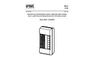
RADIORICEVITORE PER ESPANSIONI VIA RADIO DI SISTEMI DI ALLARME<br />
RECEPTEUR RADIO POUR L'EXTENSION RADIO DES SISTEMES D'ALARME<br />
RADIO RECEIVER FOR WIRELESS ALARM DETECTORS<br />
FUNKEMPFÄNGER ZUR FUNKERWEITERUNG VON ALARMSYSTEMEN<br />
RECEPTOR PARA DETECTORES INALAMBRICOS VIA RADIO<br />
<strong>SILENTRON</strong> - <strong>Made</strong> <strong>In</strong> <strong>Italy</strong><br />
COPYRIGHT <strong>SILENTRON</strong> DF5459XC070921GM<br />
1
Dichiarazione di conformità CE : il sottoscritto, in qualità di Amministratore Delegato della società scrivente, dichiara sotto la propria responsabilità che i prodotti descritti nel presente manuale sono conformi ai requisiti stabiliti<br />
dalle Direttive e relative Norme e/o specifiche tecniche che seguono:<br />
1) Direttiva CE 1999/5/CE - R&TTE - del 9 marzo 1999 (in Italia D.L. 9/05/2001 n. 269) riguardante le apparecchiature radio, le apparecchiature terminali di telecomunicazione e il reciproco riconoscimento della loro conformità. Le<br />
Norme e/o specifiche tecniche applicate sono le seguenti:<br />
- LVD e protezione della salute (art. 3(1)(a)): EN 60950-1 (2006-04), EN 50371 (2002-03)<br />
- EMC (art. 3(1)(b)): EN 301 489-1 V1.8.1 (2008-04), EN 301 489-3 V1.4.1 (2002-08), EN 301 489-7 V1.3.1 (2005-11)<br />
- Spettro radio (art. 3(2)): EN 300 220-1 V2.1.1 (2006-04), EN 300 220-2 V2.1.2 (2007-06)<br />
<strong>In</strong> accordo alla direttiva citata, allegato IV, il prodotto risulta di classe 2 pertanto può essere commercializzato e messo in servizio senza limitazioni..<br />
2) Direttiva CE 2004/108 del 15 dicembre 2004, per il riavvicinamento delle legislazioni degli Stati membri relative alla compatibilità elettromagnetica. Le Norme e/o specifiche tecniche applicate sono le seguenti: EN 50130-4 (1995-<br />
12) + A1 (1998-04) + A2 (2003-01) - EN 55024 (1998-09) +A1 (2001-10) + A2 (2003-01) - EN 301489-1 V1.8.1 (2008-04) - EN 301489-3 V. 1.4.1 (2002-08) - EN 301489-7 V1.3.1 (2005-11)<br />
3) Direttiva CE 2006/95 del 12 dicembre 2006, per il riavvicinamento delle legislazioni degli Stati membri relative al materiale elettrico destinato ad essere adoperato entro taluni limiti di tensione. E' applicata la Norma EN 60950-1<br />
(2006-049).<br />
Declaration of Conformity: the undersigned C.E.O. of Silentron S.p.A. declares under his own responsibility that the products showed in this manual are in compliance with that envisioned by the following European Community<br />
Directives:<br />
1) UE directive CE 1999/5/CE - R&TTE - dated 1999 march 9th regarding radio appliances and telecommunication terminal equipment and the reciprocal acknowledgement of their compliance. The products are in conformity with<br />
the following standards and/or other normative documents:<br />
- Healt and safety (art. 3(1)(a)): EN 60950-1 (2006-04), EN 50371 (2002-03)<br />
- EMC (art. 3(1)(b)): EN 301 489-1 V1.8.1 (2008-04), EN 301 489-3 V1.4.1 (2002-08), EN 301 489-7 V1.3.1 (2005-11)<br />
- Spectrum : (art. 3(2)): EN 300 220-1 V2.1.1 (2006-04), EN 300 220-2 V2.1.2 (2007-06)<br />
<strong>In</strong> compliance with the above normative, chapter IV, the products are in class 2 and can be commercialized and used without limitations.<br />
2) UE directive CE 2004/108 dated 2004 December 15th , for the approximation of the laws of the Member States relative to electro-magnetic compatibility. The products are in conformity with the following standards and/or other<br />
normative documents: EN 50130-4 (1995-12) + A1 (1998-04) + A2 (2003-01) - EN 55024 (1998-09) +A1 (2001-10) + A2 (2003-01) - EN 301489-1 V1.8.1 (2008-04) - EN 301489-3 V. 1.4.1 (2002-08) - EN 301489-7 V1.3.1 (2005-11)<br />
3) UE directive CE 2006/95 dated 2006 December 12th for the approximation of the laws of the Member States relative to electric material destined to be used within certain voltage limits, following the standard EN 60950-1 (2006-<br />
049)<br />
Déclaration de Conformité: le soussigné P.D.G. déclare, sous sa propre responsabilité, que les produits de ce notice sont conformes à ce que prévoient les Directives Communautaires suivantes:<br />
1) Directive CE 1999/5/CE - R&TTE - du 9 mars 1999 concernant les appareillages radio et les appareillages terminaux de télécommunication et la reconnaissance réciproque de leur conformité. Les normes appliqués sont les<br />
suivantes:<br />
- Protection de la santé: (art. 3(1)(a)): EN 60950-1 (2006-04), EN 50371 (2002-03)<br />
- EMC (art. 3(1)(b)): EN 301 489-1 V1.8.1 (2008-04), EN 301 489-3 V1.4.1 (2002-08), EN 301 489-7 V1.3.1 (2005-11)<br />
- Émission radio (art. 3(2)): EN 300 220-1 V2.1.1 (2006-04), EN 300 220-2 V2.1.2 (2007-06)<br />
Selon ces directives, joint IV, les produits sont de la classe 2 et peuvent être mis en commerce et utilisés sans limitations.<br />
2) Directive CE 2004/108/CE du 15 décembre 2004, pour le rapprochement des législations des États membres relatives à la compatibilité électromagnétique. Les normes appliquées sont les suivantes: EN 50130-4 (1995-12) + A1<br />
(1998-04) + A2 (2003-01) - EN 55024 (1998-09) +A1 (2001-10) + A2 (2003-01) - EN 301489-1 V1.8.1 (2008-04) - EN 301489-3 V. 1.4.1 (2002-08) - EN 301489-7 V1.3.1 (2005-11)<br />
3) Directive 2006/95/CE du 12 décembre 2006, pour le rapprochement des législations des États membres relatives au matériel électrique destiné à être utilisé entre certaines limites de tension. Est appliqué la norme EN 60950-1<br />
(2006-049)<br />
Erklärung der Übereinstimmung: der unterzeichnende Vorstandsvorsitzende erklärt unter eigener Verantwortung, dass die Produkte, die in dem vorliegenden Buch geschrieben sind, den Bestimmungen der folgenden EU-Richtlinien<br />
entsprechen:<br />
1) Richtlinie 1999/5/EG - R&TTE vom 9. März 1999 über Funkanlagen und Telekommunikationsendeinrichtungen und die gegenseitige Anerkennung ihrer Konformität. Die angewendeten Richtlinien sind die folgenden:<br />
- Gesundheitsschutz (art. 3(1)(a)): EN 60950-1 (2006-04), EN 50371 (2002-03)<br />
- EMC (art. 3(1)(b)): EN 301 489-1 V1.8.1 (2008-04), EN 301 489-3 V1.4.1 (2002-08), EN 301 489-7 V1.3.1 (2005-11)<br />
- Spektrum : (art. 3(2)): EN 300 220-1 V2.1.1 (2006-04), EN 300 220-2 V2.1.2 (2007-06)<br />
Übereinstimmung mit den angeführten Richtlinien, Anlage IV, die Produkte gehören der Klasse 2 an und können deswegen vermarktet und grenzenlos verwendet werden.<br />
2) Richtlinie 2004/108/EG vom 15. Dezember 2004 zur Angleichung der Rechtsvorschriften der Mitgliedstaaten über die elektromagnetische Verträglichkeit. Die angewendeten Richtlinien sind die folgenden: EN 50130-4 (1995-12)<br />
+ A1 (1998-04) + A2 (2003-01) - EN 55024 (1998-09) +A1 (2001-10) + A2 (2003-01) - EN 301489-1 V1.8.1 (2008-04) - EN 301489-3 V. 1.4.1 (2002-08) - EN 301489-7 V1.3.1 (2005-11)<br />
3)Richtlinie 2006/95/EG vom 12. Dezember 2006 zur Angleichung der Rechtsvorschriften der Mitgliedstaaten betreffend elektrische Betriebsmittel zur Verwendung innerhalb bestimmter Spannungsgrenzen. Man wendet gerade die<br />
Richtlinie EN 60950-1 (2006-049) an.<br />
Declaración de Conformidad: el abajo firmante Gerente, declara bajo su responsabilidad que los productos de esto manual están en conformidad con lo previsto por las siguientes Directivas Comunitarias:<br />
1) Directiva UE 1999/5/CE (R&TTE) del 9 de marzo de 1999, sobre equipos radioeléctricos y equipos terminales de telecomunicación y reconocimiento mutuo de su conformidad. Normativas contempladas:<br />
- Proteción de la salud: (art. 3(1)(a)): EN 60950-1 (2006-04), EN 50371 (2002-03)<br />
- EMC (art. 3(1)(b)): EN 301 489-1 V1.8.1 (2008-04), EN 301 489-3 V1.4.1 (2002-08), EN 301 489-7 V1.3.1 (2005-11)<br />
- Transmision de radio (art. 3(2)): EN 300 220-1 V2.1.1 (2006-04), EN 300 220-2 V2.1.2 (2007-06)<br />
Como previsto de esta directiva, junto IV, estos productos son de clase 2 y por esto pueden ser comercializados y utilizados sin limitación.<br />
2) Directiva UE 2004/108/CE del 15 de diciembre de 2004, relativa a la aproximación de las legislaciones de los Estados miembros en materia de compatibilidad electromagnética. Normativa contempladas: EN 50130-4 (1995-12) +<br />
A1 (1998-04) + A2 (2003-01) - EN 55024 (1998-09) +A1 (2001-10) + A2 (2003-01) - EN 301489-1 V1.8.1 (2008-04) - EN 301489-3 V. 1.4.1 (2002-08) - EN 301489-7 V1.3.1 (2005-11)<br />
3) Directiva UE 2006/95/CE del 12 de diciembre de 2006, relativa a la aproximación de las legislaciones de los Estados miembros sobre el material eléctrico destinado a utilizarse con determinados límites de tensión, en<br />
conformidad de la norma EN 60950-1 (2006-049).<br />
AVVERTENZE GENERALI - da rispettare con attenzione utilizzando i prodotti del presente manuale (ove applicabili)<br />
Leggere attentamente prima di operare sulle apparecchiature<br />
<strong>In</strong>stallazione: tutte le operazioni di installazione, manutenzione e/o modifica delle presenti centrali e loro apparecchiature accessorie devono essere effettuate da<br />
personale tecnico qualificato. Tali operazioni possono essere soggette a ulteriori norme tecniche specifiche che devono essere rispettate. L'apparecchiatura è<br />
prevista per essere utilizzata esclusivamente all’interno di immobili, protetta da esposizioni ad elevate o bassissime temperature nonché da manipolazioni da parte<br />
di bambini e/o persone prive del buon senso comune ai sensi del C.C.<br />
Collegamenti elettrici: ogni collegamento elettrico senza eccezioni deve essere effettuato a regola d’arte fissando tutti i fili come previsto onde evitarne il distacco<br />
accidentale e chiudendo correttamente i contenitori e le protezioni degli apparecchi. E' fatto obbligo di scollegare tutti i collegamenti elettrici superiori a 25V sia CC<br />
che CA prima di aprire contenitori di apparecchi in funzione.<br />
Alimentazione esterna: 230V CA 50 Hz - collegarsi attraverso un sezionatore bipolare o meglio, una spina normalizzata estraibile.<br />
Batterie ricaricabili e/o pile di qualunque tipo: questi apparecchi utilizzano batterie o pile, le quali sono potenzialmente dannose in quanto inquinanti, quindi<br />
pericolose per la salute pubblica. Sostituire le batterie e/o pile esclusivamente con modelli equivalenti, collocarle e collegarle rispettando la polarità indicata nelle<br />
istruzioni. E’ obbligatorio smaltire quelle esauste secondo le Norme vigenti, anche nel caso di rottamazione degli apparecchi, dai quali dovranno essere<br />
preventivamente estratteggere le mani con guanti al silicone onde evitare lesioni.<br />
Responsabilità: il fabbricante declina ogni responsabilità conseguente a errata installazione e/o manutenzione, errato uso e/o mancato uso degli apparecchi forniti.<br />
Garanzia in Italia:<br />
1) presenza di vizi occulti: la garanzia è prestata nei termini previsti dal Codice Civile, in particolare dagli art. 1490, 1492, 1495 C.C.<br />
2) buon funzionamento: la garanzia è prestata ai sensi dell'articolo 1512 del Codice Civile per un periodo di circa 3 anni dalla data di produzione; fa fede la data di<br />
scadenza scritta su apposita etichetta interna all'apparecchiatura. Anche ove il prodotto sia fornito completo di batteria o pila, quest'ultima va considerata<br />
"accessorio gratuito soggetto a consumo" non coperto da garanzia.<br />
3) la garanzia al privato consumatore (D.Lgs.2-2-02 n.24) deve essere fornita dall'ultimo venditore del prodotto a termini di legge.<br />
Copyright : tutti i diritti relativi al presente manuale sono di proprietà Silentron s.p.a. E' espressamente vietata la riproduzione parziale o totale dei testi e delle<br />
immagini qui riportate, così come l'inserimento in rete W.E.B. e/o la diffusione pubblica con qualunque mezzo.<br />
Conformità normativa: oltre a quanto descritto nella dichiarazione di conformità, si aggiunge<br />
- Prodotto conforme alla norma EN 50131-1 - Classe ambientale 2 - Prodotto di categoria I secondo la Norma 300.220 - 1 (04/2006)<br />
<strong>SILENTRON</strong> - <strong>Made</strong> <strong>In</strong> <strong>Italy</strong><br />
COPYRIGHT <strong>SILENTRON</strong> DF5459XC070921GM<br />
2
1) CARATTERISTICHE GENERALI e POSSIBILITA' DI IMPIEGO<br />
Impiego come ricevitore di allarmi: R-Evolution 12 è un radioricevitore DualBand a 12 zone che controlla fino a 32 periferiche via radio<br />
permettendo di ampliare impianti tradizionali senza difficoltosa posa di cavi : si possono installare Sensor Top e Slim per la protezione di infissi<br />
contro l'apertura e lo scasso; Silent Pir per segnalare l'avvicinamento dall'esterno; barriere Laserbeam per controllare l'attraversamento di<br />
accessi, telecomandi PCK e tastiere Keypad per attuazioni bistabili e monostabili. Il ricevitore Funziona con qualunque centrale, da cui prende<br />
alimentazione e a cui fornisce 12 uscite di allarme e 4 di anomalia tramite relè libero da potenziale; 16 spie led visualizzano e memorizzano il<br />
funzionamento di ogni zona realizzando il controllo totale ed il test permanente del sistema.<br />
Impiego per automazioni generiche: R-Evolution 12 può essere utilizzato per comandare a distanza apparecchi elettrici di ogni tipo, come<br />
cancelli automatici, luci, irrigatori e simili. <strong>In</strong> questo caso occorre tenere conto dell’assorbimento del carico collegato e interporre un relè<br />
adeguato (12V CC) fra il ricevitore ed il carico asservito: questo è obbligatorio quando il carico lavora in Corrente Alternata. Ovviamente è<br />
possibile usare alcune uscite per l’allarme ed altre per comando carichi, programmandole opportunamente.<br />
2) CARATTERISTICHE TECNICHE<br />
Alimentazione: 10-14 V CC Assorbimento: 60 mA tipico Visualizzazioni: 12 led di allarme + 4 di anomalia<br />
<strong>In</strong>gressi - Uscite (vedere disegno e morsettiera)<br />
ingresso "reset" = Comando cancellazione memorie led proveniente dalla centrale con polarità programmabile (dip-switch 1)<br />
uscite 1 - 12 : contatti allarme a relé programmabile NC / NO (SW 3) - max 0,1A 12V CC<br />
uscite Tamper - Battery - Supervisione - Scanner : contatti allarme a relé programmabile NC / NO - max 0,1A 12V CC<br />
Ricezione radio: due ricevitori supereterodina - sensibilità - 105 db - frequenza >400MHz e > 850MHz - frequenze e caratteristiche a norma di<br />
legge - indicate approssimativamente per motivi di sicurezza.<br />
Temperatura di stoccaggio e funzionamento - Grado di protezione - Peso - Dimensioni: vedere figura<br />
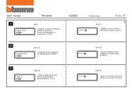
3) FUNZIONAMENTO E PREDISPOSIZIONI DA EFFETTUARSI IN FASE DI PROGRAMMAZIONE:<br />
Dip-switch 1 on : il ricevitore è disinserito collegando l'ingresso reset a positivo - è inserito ad ingresso aperto o collegato a negativo.<br />
Dip-switch 1 off : il ricevitore è disinserito collegando l'ingresso reset a negativo (GND) - è inserito ad ingresso aperto o collegato a positivo.<br />
Dip-switch 2 on : la memoria di allarme led è visibile in disinserito e si azzera al successivo inserimento - dip off = memoria disabilitata.<br />
Dip-switch 3 on : il buzzer interno segnala inserimento (BEP-BEP-BEP) e disinserimento (BEP) e eventi Tamper - Battery - Supervisione -<br />
Scanner con ulteriori 5 BEP quando si commuta da inserito a disinserito e viceversa - dip off = buzzer disabilitato.<br />
Dip-switch 4 on : a seguito di allarme i relè 1 - 12 commutano anche in disinserito - dip off = commutano soltanto in inserito<br />
Dip-switch 5 on : a seguito di qualunque allarme il contatto del relè 12 si apre per 2 sec. circa (OR degli allarmi - ved. disegni)<br />
Dip-switch 6 : non utilizzato<br />
4) FUNZIONAMENTO DELLE USCITE PROGRAMMABILI A RELÈ’ :<br />
L'apparecchio è fornito con 16 uscite NC libere da potenziale, che si aprono per 2 secondi in allarme. <strong>In</strong> questa configurazione il led di zona<br />
lampeggia lentamente durante la programmazione della zona. Premendo una volta SW 3 l'uscita diventa NO, che si chiude per 2 secondi in<br />
allarme: il led lampeggia velocemente. Premendo ancora SW 3 l'uscita diventa NO che chiude per 3 minuti : il led è acceso fisso.<br />
Programmando telecomandi PCK (pulsanti rosso e verde) l'uscita relè è sempre bistabile (verde = aperta - rosso = chiusa).<br />
Programmando Sensor (contatto per porta/finestra) con funzione di segnalazione "porta aperta" il relè segue l'apertura e chiusura dell'infisso.<br />
5) SITUAZIONI DI ALLARME (esse sono sempre visualizzate temporaneamente o memorizzate dai led relativi):<br />
allarme rivelatori : una trasmissione di allarme di un rivelatore provoca la commutazione del relativo relè di zona come programmato<br />
manomissione : l'apertura del ricevitore e/o una trasmissione di manomissione dei rivelatori provoca sempre commutazione del relè "tamper"<br />
batteria bassa : una tale trasmissione di un rivelatore provoca sempre la commutazione del relè "battery"<br />
supervisione : mancati segnali di supervisione provocano sempre la commutazione del relè relativo al più tardi dopo 8 ore dall'evento.<br />
disturbi radio : disturbi tali da inibire la corretta ricezione su entrambe le frequenze provocano sempre la commutazione del relè relativo.<br />
6) PRIMA PROGRAMMAZIONE<br />
Tale operazione avviene per autoapprendimento, predisponendo R-Evolution 12 a ricevere la trasmissione del rivelatore sulla zona prescelta ed<br />
effettuando quindi tale trasmissione. Si possono programmare tutti i rivelatori e/o telecomandi Silentron. La programmazione permane anche<br />
scollegando l'alimentazione e si cancella soltanto con l'operazione di "reset".<br />
Reset totale : alimentare l'apparecchio aperto e premere S 1 per 10 secondi : trascorso questo tempo un beeeeep conferma la cancellazione<br />
delle programmazioni esistenti. Il led 1 lampeggia in attesa di programmazione del primo rivelatore.<br />
Programmazione del primo rivelatore : selezionare il funzionamento dell'uscita come desiderato (vedere 4) ed inserire la pila nel rivelatore.<br />
Un BEP conferma l'avvenuta programmazione. 3 BEP indicano che quel rivelatore è già stato programmato.<br />
Programmazione degli altri rivelatori: spostarsi di zona premendo il tasto S2 poi procedere come sopra.<br />
Programmazione di telecomandi : scegliere la zona desiderata premendo ripetutamente il tasto S2 . Premendo insieme i tasti rosso e verde<br />
si ottiene il funzionamento bistabile (rosso=ON – verde=OFF). Premendo un tasto giallo o blu per 10 secondi si ottiene un comando<br />
monostabile temporizzato a 2 secondi o 3 minuti come programmato (vedere par. 4). Un breve BEEP conferma la programmazione effettuata.<br />
Uscita da "programmazione" : automatica dopo 1 minuto senza operazioni oppure premendo insieme S1 ed S2.<br />
N.B. Nei canali ove sono stati programmati telecomandi e/o tastiere, non è possibile programmare sensori.<br />
7) CANCELLAZIONI / MODIFICHE DI PROGRAMMAZIONE<br />
Per tali operazioni occorre aprire il ricevitore, dopo aver bloccato la segnalazione di manomissione sulla centrale, e premere S1 per entrare in<br />
"programmazione". Per cancellare il rivelatore / telecomando di una zona occorre individuarla premendo successivamente S2, poi premere S1<br />
per 10 secondi (BEP di conferma). Per aggiungere un rivelatore / telecomando individuare la zona e fargli trasmettere il codice.<br />
8) SEGNALAZIONE DI EVENTI (durante il normale funzionamento)<br />
Ogni allarme è segnalato temporaneamente dai led, per cui il test del sistema è immediato: ad esempio in caso di allarme del rivelatore 5<br />
lampeggerà il led 5; in caso di pila scarica dello stesso rivelatore lampeggerà il led 5 ed anche quello "battery" e così via.<br />
Attenzione: ad ogni manovra di inserimento / disinserimento l'apparecchio segnala (vedere punto 3 dip-switch 3) con 5 BEP del buzzer interno<br />
gli eventi occorsi durante l'ultimo periodo di inserito o disinserito : occorre che tali segnalazioni non siano ignorate in quanto potrebbero<br />
comportare mancato funzionamento del sistema o di sue parti. <strong>In</strong> particolare se si esclude il buzzer è responsabilità dell'installatore effettuare<br />
tutti i collegamenti necessari in modo tale che eventuali pile scariche, manomissioni, disturbi radio e mancate supervisioni siano altrimenti<br />
segnalate attraverso le apposite uscite relè opportunamente collegate alla centrale utilizzata.<br />
<strong>SILENTRON</strong> - <strong>Made</strong> <strong>In</strong> <strong>Italy</strong><br />
COPYRIGHT <strong>SILENTRON</strong> DF5459XC070921GM<br />
3
AVERTISSEMENTS GENERAUX – à respecter avec attention en utilisant les produits du présent manuel (ou applicables)<br />
Lire attentivement avant d'intervenir sur les appareils<br />
<strong>In</strong>stallation: toutes les opérations d'installation, d'entretien et/ou de modification du système et de ses appareils doivent être effectuées par un personnel<br />
technique qualifié.<br />
Ces opérations peuvent être sujettes à des normes techniques spécifiques qui doivent être respectées.<br />
L'appareillage est prévu pour être utilisé exclusivement à l'intérieur d'immeubles, protégé des températures trop élevées ou trop basses ainsi que des manipulations<br />
par des enfants et/ou personnes privées du bon sens commun aux termes du C.C.<br />
Branchements électriques: tout branchement électrique -et ceci sans aucune exception- doit être effectué selon les normes en fixant tous les fils comme<br />
prévu afin d'en éviter l'arrachement accidentel, et en prenant soin de refermer les boîtiers et les protections des appareils.<br />
Il est obligatoire de défaire tous les branchements électriques supérieurs à 25V tant en CC qu'en CA avant d'ouvrir les boîtiers des appareils en fonction.<br />
Alimentation extérieure: 230V CA 50 Hz - se connecter à travers un sectionneur bipolaire ou mieux encore à travers une fiche normalisée extractible.<br />
Batteries rechargeables et/ou piles de n’importe quel type : ces appareils utilisent des batteries ou des piles qui sont potentiellement nuisibles en tant<br />
qu’élément polluant, et par conséquent dangereuses pour la santé publique. Substituer les batteries et/ou les piles exclusivement avec des modèles équivalents, les<br />
placer en respectant la polarité indiquée sur le mode d’emploi. Il est obligatoire d’éliminer celles usées selon les Normes en vigueur, également en cas de démolition<br />
des appareils, desquels elles devront être auparavant extraites en les restituant au vendeur de l’appareil ou bien en les déposant dans les conteneurs spécifiques<br />
mis à la disposition par le réseau de distribution. En cas de déversement du liquide des piles ou des batteries se protéger les mains avec des gants au silicone afin<br />
d’éviter des blessures.<br />
Responsabilité: le fabricant décline toute responsabilité dérivant d'une installation erronée et/ou d'un entretien, d'une mauvaise utilisation et/ou d'un manquement à<br />
l’utilisation des appareils fournis.<br />
Garantie: la garantie est valable jusqu'à son échéance mentionnée sur l'étiquette contenue dans l'appareillage, dans les limites prévues par la Convention de<br />
Vienne de 1980 sur la Vente <strong>In</strong>ternationale des Marchandises.<br />
Copyright : tous les droits relatifs au présent manuel sont réservés à Silentron s.p.a. La reproduction partielle ou totale des textes et des images ici contenus est<br />
expressément interdite, tout comme l'insertion sur le réseau W.E.B. et/ou la diffusion publique de toute nature.<br />
Conformité normative: en plus à celui indiqué dans la déclaration de conformité on précise :<br />
Produit conforme à la norme EN 50131-1- Classe ambiant 2 – Produit de catégorie I selon la Norme 300.220-1 (04/2006)<br />
CARACTERISTIQUES GENERALES et MODE D'EMPLOI<br />
Utilisation comme récepteur d’alarme: R-Evolution 12 est un récepteur radio DualBand à 12 sorties pour 32 émetteurs radio max., pour<br />
agrandir un système traditionnel sans poser de câble : des contacts de portes Sensor pour la protection contre l’ouverture ou le vandalisme,<br />
Silent Pir pour la protection contre l’extérieur, Laserbeam, barrières sans fil pour le contrôle externe des accès, télécommandes PCK et clavier<br />
Keypad, pour mise en service et hors service. Le récepteur fonctionne avec tout type de centrale, dont elle tire l’alimentation, et fournit 12 relais<br />
d’alarme plus 4 d’anomalie ; 16 LED permettent la visualisation et la mémorisation du fonctionnement des zone, pour obtenir le contrôle totale<br />
et un test permanent du système. Utilisation pour domotique générique : R-EVOLUTION 12 peut être utilisé pour commander à distance des<br />
appareil électrique de tout type : portails automatiques, lumières, arrosages, etc. Dans ce cas, tenir compte de la consommation de la charge<br />
reliée et placer un relais suffisant (12 V CC), entre le récepteur et la charge à commander : ceci est obligatoire lorsque la charge fonctionne sur<br />
courant alternatif. Bien entendu, il est possible d’utiliser certaines sorties pour de l’alarme et d’autres pour des commandes domotiques, en les<br />
programmant opportunément.<br />
FONCTIONNEMENT ET PREDISPOSITION A EFFECTUER LORS DE LA PROGRAMMATION<br />
Dip-switch Etat Action<br />
1 ON<br />
Si l’entrée reset est relié à un positif,<br />
le récepteur est MHS (mis hors service)<br />
Si l’entrée reset est ouverte ou reliée à un négatif, le récepteur est MES (mis en service)<br />
1 OFF<br />
Si l’entrée reset est relié à un négatif (GND), le récepteur est MHS (mis hors service)<br />
Si l’entrée reset est ouverte ou reliée à un positif, il est MES (mis en service)<br />
2 ON<br />
La mémoire d’alarme (LED) est visible lors des MHS et s’efface à la prochaine MES. Dip 2 = OFF : Pas de<br />
mémoire d’alarme<br />
3 ON<br />
Le Buzzer indique avec 3 beep les MES, avec 1 beep les MHS, avec 5 beep sucessifs : les sabotages (tamper),<br />
les batteries basses, le manquement de supervision, le scanner. Dip 3 = OFF : buzzer muet<br />
4 ON Les relais 1-12 commutent même si le récepteur est MHS – Dip4=OFF: les relais commutent uniquement si MES<br />
Dip-switch 5 on : suite à une alarme quelconque, le contact relais n° 12 s’ouvre pour 2 secondes environ (OR des alarmes – voir dessins)<br />
Dip-swtich 6 : non utilisé<br />
FONCTIONNEMENT DES RELAIS PROGRAMMABLES<br />
Configuration initiale : les16 relais à libre potentiel sont NF et s’ouvrent 2 sec. en cas d’alarme - en programmation, par défaut : le LED de la<br />
zone clignote lentement<br />
1 ère pression sur SW3 : le relais passe NO et se ferme 2 sec. en cas d’alarme – le LED clignote rapidement.<br />
2 nde pression sur SW3 : le relais est NO et se ferme 3 minutes – le LED reste allumé et fixe.<br />
Programmation des télécommandes PCK (touches rouge et verte) : le relais passe toujours bistable (touche verte : ouvert –rouge : fermé).<br />
Programmation SENSOR en « Porte ouverte » : le relais suit l’ouverture et la fermeture de l’huisserie.<br />
SITUATION D’ALARME (visualisation temporaire ou mémorisation du LED correspondant)<br />
Evénement Réaction<br />
Alarme<br />
La transmission d’alarme d’un détecteur provoque la commutation du relais de la zone correspondante.<br />
détecteur<br />
Sabotage L’ouverture du récepteur et/ou la transmission de sabotage des détecteurs provoque la commutation du relais « tamper »<br />
Batterie basse La transmission de cette information par un détecteur provoque la commutation dur relais « battery ».<br />
Supervision L’absence de signal de supervision d’un détecteur provoque la commutation du relais « supervision », dans les 8 h max.<br />
Troubles radio Les troubles radio sur les 2 fréquences perturbant la correcte réception provoque la commutation du relais « scanner »<br />
1 ère PROGRAMMATION<br />
La programmation s'effectue par autoapprentissage : placer R-Evolution en programmation et effectuer l'émission radio de programmation sur<br />
canal choisi. Tous les détecteurs et les télécommandes Silentron peuvent être programmés. Seule l’opération de reset efface la programmation.<br />
Si le récepteur est déconnecté, la mémorisation reste.<br />
Reset total : avec l’appareil ouvert, alimenter-le en appuyant 10 secondes sur S1 : un beeeep confirme le reset total. Le LED 1 clignote dans<br />
l’attente de programmation du 1 er émetteur.<br />
Programmation du 1 er émetteur : avec SW3, choisir le fonctionnement de la sortie (voir plus haut) – régler les éventuels dip du détecteur, placer<br />
–y la pile : un bep confirme l’opération. 3 bep indiquent que le détecteur est déjà programmé.<br />
Programmation des émetteurs suivants : appuyer sur S2 pour changer de canal puis répéter l’opération comme pour le 1 er émetteur.<br />
<strong>SILENTRON</strong> - <strong>Made</strong> <strong>In</strong> <strong>Italy</strong><br />
COPYRIGHT <strong>SILENTRON</strong> DF5459XC070921GM<br />
4
Programmation des télécommandes : Programmation des télécommandes : choisir le groupe désiré en appuyant plusieurs fois sur la touche<br />
S2. En appuyant simultanément sur les touches rouges et vertes, un fonctionnement bistable est obtenu (ROUGE : ON - VERT :OFF). En<br />
appuyant sur une touche jaune ou bleue pendant 10 secondes, est obtenue une commande monostable temporisée de 2 secondes ou 3<br />
minutes selon le type de programmation (voir paragraphe 4). Un BEEP confirme la programmation effectuée.<br />
Programmation d’un clavier : choisir le canal désiré avec S2 - Code clavier : composer le code et appuyer simultanément 2 sec sur les touches<br />
rouge et verte. Bep de confirmation. Le relais sera bistable (MES / MHS). Touche panique : choisir le canal désiré avec S2 - brancher la pile<br />
dans le clavier. L’action de la touche est identique à celle d’un détecteur (monostable).<br />
Attention : ne pas mélanger les émetteurs bistables et monostables sur un même canal : utiliser des canaux distincts.<br />
Sortie de programmation : attendre 1 min. sans transmission radio ni appuyer sur 1 touche ou appuyer simultanément sur S1 et S2.<br />
NB: il est impossible de programmer des détecteurs sur les canaux où ont été programmés des télécommandes et/ou des codes claviers.<br />
ANNULER OU MODIFIER UNE PROGRAMMATION<br />
Bloquer l’indication de sabotage de la centrale ; ouvrir le capot du récepteur ; appuyer sur S1 et entrer en programmation ; appuyer sur S2 et se<br />
placer sur le canal désiré ; appuyer 10 sec sur S1 ; bep confirmant l’annulation de programmation du canal. Programmer un nouvel émetteur :<br />
voir Programmation des émetteurs suivants dans 1 ère programmation.<br />
INDICATION DES EVENEMENTS<br />
Les test sont permanents car chaque événement est indiqué temporairement par le(s) LED correspondant(s). En cas d’alarme du détecteur 5,<br />
le LED 5 clignote. Si ce même détecteur a une batterie basse, le LED 5 clignote simultanément à celui de batterie basse, et ainsi de suite.<br />
Attention : si dip 3 = ON, lors des manœuvres de MES/MHS du récepteur, 5 bep du buzzer indiquent tous les événements intervenus lors du<br />
précédent état. Considérer ces informations, car elles indiquent des manutentions nécessaires du système. Si dip 3 = OFF, le buzzer est<br />
exclu ; l’installateur est alors tenu d’effectuer toutes les connections nécessaires entre les sorties d’informations de piles basses, sabotages,<br />
troubles radio et manquement supervision et les entrées correspondantes de la centrale, pour que l’utilisateur soit informé de ces événements.<br />
CARACTÉRISTIQUES TECHNIQUES<br />
Alimentation: 10-14 VCC Consommation : 60mA typique Visualisation : 12 voyants led d’alarme + 4 led d’information d’anomalie<br />
Sorties électriques (voir dessin et borniers) : Entrée « reset » : commande de anulation memoires par voyants, provenant de la centrale avec<br />
polarité programmable (dip-switch 1)<br />
Sorties 1 – 12 : contacts d’alarme à relais programmable NF / NO (SW3) – max 0,1A 12V CC<br />
Sortie Tamper – Batterie – Supervision – Scanner : contact d’alarme à relais programmable NF / NO - max 0,1A 12V CC<br />
Réception radio: double récepteur superethérodine - Sensibilité: - 105 dB - fréquence > 400 MHz > 850 MHz - fréquence et caractéristiques<br />
conformes aux normes : valeurs approx. pour raisons de sécurité<br />
Température de stock et fonctionnement Dimensions : Poids degré de protection voir dessi<br />
GENERAL NOTICES AND WARNIGS - To be respected when the application is possibile.<br />
Read carefully before using the appliances<br />
<strong>In</strong>stallation: all installation, maintenance and/or modification of these control units and their devices must be carried out by qualified technical staff. These<br />
operations can be subject to specific technical Standards which must be complied with. The device is envisioned to be used exclusively inside buildings protected<br />
from exposure to very high and very low temperatures as well as tampering by children and/or persons without common sense for the purpose and effects of the<br />
Civil Code.<br />
Electrical connections: all electrical connections, without exception, must be made perfectly fixing all wires as envisioned in order to prevent accidental<br />
disconnection and closing the containers and protection devices correctly. It is mandatory to disconnect all electric connections exceeding 25V in DC and AC before<br />
opening the containers of functioning appliances.<br />
External power supply: 230V CA 50 Hz - connect in compliance with country law regulations<br />
Batteries Rechargeable accumulators and/or batteries of any type: these appliances use accumulators or batteries, which are potentially dangerous as they are<br />
pollutant, therefore dangerous to the health of the public. Replace the accumulators and/or batteries exclusively with same models, position and connect them<br />
respecting the polarity indicated in the instructions. It is mandatory to dispose of accumulators/waste batteries according to the Standards in force. This is also the<br />
case when the machines must be scrapped. The accumulators/batteries must be previously removed, returning them to the appliance dealer or depositing them in<br />
the relevant containers made available by the distribution network. If liquid should escape from the batteries or accumulators, use silicone gloves to protect the<br />
hands and prevent injury.<br />
Liability: the manufacturer declines all liability consequent to incorrect installation and/or failure to use the devices supplied.<br />
Warranty: the warranty is valid until the expiry written on the label inside the device in the terms envisioned by the Vienna Convention of 1980 regarding the<br />
<strong>In</strong>ternational Sale of Goods.<br />
Copyright: all rights relative to this manual are the property of Silentron s.p.a. It is prohibited to partially or totally reproduce the texts and imaged herein, as is the<br />
introduction into W.E.B. network and/or public distribution with any means.<br />
Standard conformity: more of CE declaration, the products are in compliance with EN 50131-1 - environmental class 2 and they are declared of category I by the<br />
standard 300.220 - 1 (04/2006)<br />
1) GENERAL FEATURES and USE POSSIBILITIES<br />
Use as alarm receiver: R-Evolution 12 is a Dualband radio receiver with 12 zones, able to store up to 32 detectors for wireless extension of a<br />
traditional alarm system: Sensor Top and Slim contacts for protection of doors and windows against opening/shock; Silent PIR detector for<br />
outdoor protection; Laserbeam barriers for control over the access areas, remote controls PCK and keypads for bistable and monostable<br />
operations. The receiver works with every control panel, from which it is supplied and to which gives out 12 alarm outputs and 4 anomaly<br />
outputs by means of a free contact relay.; 16 LEDs display and store the functioning of every zone, thus realizing a total control and a<br />
permanent testing of the system.<br />
Use for general automations: R-Evolution 12 can be used to operate whatever electrical device at a distance, like automatic gates, lights,<br />
irrigators and similar. <strong>In</strong> this case it is necessary to consider the electrical input of the connected device and mount a suitable relay (12V DC)<br />
between the receiver and the electrical device itself: this is absolutely necessary when the device works with Alternating Current (AC) Of course<br />
it is possible to use some outputs for alarm information and others for electrical loads operation, by programming them in the suitable way.<br />
2) TECHNICAL FEATURES<br />
Power supply: 10-14 V DC Power rating: 60 mA standard LED visualization: 12 for alarm + 4 for anomaly<br />
<strong>In</strong>puts - outputs : see drawing and terminal board<br />
reset input: reset of alarm latches by led from control panel – programmable polarity by dip-switch 1<br />
Outputs 1-12: alarm outputs with programmable relay NC/NO (SW3) – max 0,1A 12 V DC<br />
Tamper – Battery – Supervision – Scanner: : alarm outputs with programmable relay NC/NO – max 0,1A 12 V DC<br />
Radio receiving: two superheterodyne receivers – 105 db - frequency > 400 MHz and > 850 MHz - frequency and features in compliance with<br />
the law - approx. indication for security reasons.<br />
Stock and operating temperature - Protection degree - Weight – Dimensions: see drawing.<br />
<strong>SILENTRON</strong> - <strong>Made</strong> <strong>In</strong> <strong>Italy</strong><br />
COPYRIGHT <strong>SILENTRON</strong> DF5459XC070921GM<br />
5
3) FUNCTIONING AND OPERATIONS TO CARRY OUT DURING PROGRAMMING<br />
Dip-switch 1 ON : to arm > reset input free – to disarm > positive closed to reset input<br />
Dip-switch 1 OFF : to arm >reset input free – to disarm > negative (GND) closed to reset input<br />
Dip-switch 2 ON : the alarm memory LED is visible when the receiver is disarmed and reset itself at the following arming – OFF=memory not<br />
active<br />
Dip-switch 3 ON : the built-in buzzer indicates arming (BEP-BEP-BEP) and disarming (BEP) and the events Tamper – Battery – Supervision –<br />
Scanner with additional 5 BEP while arming and disarming – OFF = buzzer not active<br />
Dip-switch 4 ON : after an alarm the relays 1-12 switch also in disarmed condition – OFF = they switch only in armed condition<br />
Dip-switch 5 ON : after an alarm coming from whatever line, the relay contact 12 opens for approx. 2 seconds (“OR” function of the alarms -<br />
see drawings).<br />
Dip-switch 6 : not used<br />
4) FUNCTIONING OF RELAY OUTPUTS:<br />
The 16 free contacts are NC and temporarily open in case of alarm (for 2 seconds). <strong>In</strong> this configuration the LED of the programming zone<br />
flashes slowly By pressing once SW 3 the output becomes NO and closes for 2 seconds in case of alarm: the LED flashes quickly. By pressing<br />
again SW 3 the output becomes NO and closes for 3 minutes: the LED light remains on.<br />
While programming the remote controls PCK (red and green buttons) the relay output is always bistable (green=open – red=closed).<br />
While programming the Sensor door/window contacts with “open door” warning option, the relay follows the opening or closing of the<br />
door/window (i.e. it remains open if the door/window remains open).<br />
5) ALARM SITUATIONS (they are always temporarily displayed or stored by the relevant LEDs)<br />
Alarm from detectors: an alarm transmission from a detector switches the relevant relay according to programming<br />
Tamper: the opening of the receiver and/or the transmission of tamper on detectors always switch the “tamper” relay<br />
Low battery: this transmission always switches the “battery” relay<br />
Supervision: unsuccessful supervision signals always switch the relevant relay latest after 8 hours from the event<br />
Antiscanner: possible radio noises which inhibit the correct receiving on both frequencies always switch the relevant relay<br />
6) FIRST PROGRAMMING<br />
This operation takes place through self-learning, by preparing the R-Evolution 12 to receive the detector transmission on a selected zone and by<br />
carrying out the transmission itself. It is possible to program all Silentron detectors and/or remote controls. The programming remain stored even<br />
after disconnecting power supply: it can be cancelled only with a “reset” operation.<br />
Total reset: supply the receiver while open and press S1 for 10 seconds: a “beep” confirms the complete cancellation of existing programming.<br />
LED 1 flashes, waiting for programming of the first detector.<br />
Programming of first detector: select the requested output functioning (see 4) and put the battery inside the detector. One “bep” confirms that<br />
programming has been successful, 3 “bep” indicates that the detector was already programmed.<br />
Programming of further detectors: change zone by pressing the S2 button and go on as described above.<br />
Programming of remote controls: choisir le groupe désiré en appuyant plusieurs fois sur la touche S2. En appuyant simultanément sur les<br />
touches rouges et vertes, un fonctionnement bistable est obtenu (ROUGE : ON - VERT :OFF). En appuyant sur une touche jaune ou bleue<br />
pendant 10 secondes, est obtenue une commande monostable temporisée de 2 secondes ou 3 minutes selon le type de programmation (voir<br />
paragraphe 4). Un BEEP confirme la programmation effectuée.<br />
End of programming: when programming is finished, press together S1 and S2. Warning: if you do not press any button or no transmissions<br />
are sent for 1 minute, programming is automatically ended.<br />
NOTE: in the channels where remote controls and/or keypads have been programmed, it is not possible to program any detector<br />
7) CANCELLATION / MODIFICATION OF PROGRAMMING<br />
For such operations it is necessary to open the receiver, after stopping the tamper warning sent to the control panel, and press S1 to enter<br />
programming mode. To cancel a detector / remote control of a zone it is necessary to select the zone and press S2 , then S1 for 10 seconds<br />
(you hear a confirmation “bep”). To add a detector / remote control, select the requested zone and let the detector /remote control send the<br />
transmission code.<br />
8) EVENTS SIGNALLING (during normal functioning) Every alarm is temporarily signalled by the LEDs, therefore the system testing is<br />
immediate: for example in case of alarm of detector no. 5 the LED no. 5 will be flashing; or in case of low battery of detector no. 5 again, both<br />
LED no.5 and the battery LED will be flashing, and so on.<br />
Warning: at every arming/disarming of control panel, the receiver signals with 5 “bep” (see point 3 – dip-switch 3) the events which have taken<br />
place during the last armed / disarmed period: this signalling should not be ignored, because it could cause a failure in the functioning of the<br />
system or of parts of it. If the buzzer is excluded as requested by the end user, the installer has the responsibility to carry out all the necessary<br />
connections so that signals of low battery, tamper, scanner or lack of supervision will be sent through the proper relay outputs connected to the<br />
control panel.<br />
<strong>SILENTRON</strong> - <strong>Made</strong> <strong>In</strong> <strong>Italy</strong><br />
COPYRIGHT <strong>SILENTRON</strong> DF5459XC070921GM<br />
6
ALLGEMEINE HINWEISE - Aufmerksam beachten unter Benutzung der Produkte des Handbuchs (falls anwendbar)<br />
Vor dem Betrieb der Geräte aufmerksam lesen<br />
<strong>In</strong>stallation: Alle <strong>In</strong>stallations- und Wartungsarbeiten und/oder Veränderungen der bestehenden Zentralen und ihrer Zusatzgeräte müssen von technisch<br />
qualifiziertem Personal durchgeführt werden.<br />
Diese Arbeiten können spezifischen, technischen Normen unterliegen, die respektiert werden müssen.<br />
Das Gerät ist ausschließlich für den Einsatz im <strong>In</strong>nern von Gebäuden vorgesehen, wo es vor hohen und sehr niedrigen Temperaturen sowie vor Manipulationen<br />
durch Kinder bzw. Personen ohne gesunden Menschenverstand im Sinne des BGB geschützt ist.<br />
Elektrische Anschlüsse: Alle elektrischen Anschlüsse müssen ausnahmslos fachgerecht durchgeführt und alle Drähte wie vorgesehen befestigt werden,<br />
um ein unbeabsichtigtes Lösen zu vermeiden. Die Gehäuse und Schutzvorrichtungen der Geräte sind einwandfrei zu schließen. Vor Öffnen der Gehäuse<br />
von in Betrieb befindlichen Geräten, alle elektrischen Anschlüsse über 25 V Gleich- oder Wechselstrom abtrennen.<br />
Außenversorgung: 230V~ 50 Hz - Anschluss über einen zweipoligen Trennschalter oder besser über einen genormten, Herausziehbahren Stecker.<br />
Wiederaufladbare Akkus bzw. Batterien beliebigen Typs: <strong>In</strong> diesen Geräten werden Akkus oder Batterien eingesetzt, die die Umwelt verschmutzen können und<br />
daher gesundheitsschädlich sind. Ersetzen Sie Akkus bzw. Batterien ausschließlich durch gleichwertige Modelle und beachten Sie beim Einsetzen/Anschließen die<br />
in der Anleitung angegebene Polung. Verbrauchte Batterien und Akkus müssen gemäß den geltenden Bestimmungen entsorgt werden, auch bei Verschrottung der<br />
Geräte, aus denen sie vorher entnommen werden müssen. Dazu können sie dem Händler der Geräte zurückgegeben oder in die dafür bereitgestellten<br />
Sammelbehälter des Verteilernetzes eingeworfen werden. Sollte aus Batterien bzw. Akkus Flüssigkeit ausgelaufen sein, tragen Sie Schutzhandschuhe aus Silikon,<br />
um Verletzungen an den Händen vorzubeugen.<br />
Haftung: Der Hersteller lehnt jegliche Verantwortung infolge unsachgemäßer <strong>In</strong>stallation und/oder Wartung, unsachgemäßer und/oder nicht erfolgter Benutzung der<br />
gelieferten Geräte ab.<br />
Garantie: die Garantie wird bis zum Fälligkeitsdatum auf dem Etikett im <strong>In</strong>nern des Geräts gemäß der Bestimmungen der Wiener Konvention von 1980 zum<br />
internationalen Warenverkauf geleistet..<br />
Copyright : alle Rechte an der vorliegenden Anleitung sind Eigentum von Silentron s.p.a.<br />
Die teilweise oder vollständige Reproduktion der hier abgedruckten Texte und Bilder, sowie das Einstellen in das <strong>In</strong>ternet und/oder die öffentliche Verbreitung über<br />
jedwedes Medium sind ausdrücklich verboten.<br />
Nach dem Gesetz: abgesehen von den bereits in der Übereinstimmungserklärung beschriebenen Punkte:<br />
Produkt entsprechend der Norm EN 50131-1 – Umweltklasse 2 – Produkt der Kategorie I entsprechend der Norm 300.220 – 1 (04/2006)<br />
1. Allgemeine Eigenschaften – EinsatzmöglichkeitEN<br />
Einsatz als Alarmempfänger: R-Evolution 12 ist ein Funkempfänger in Doppelfrequenz „DualBand“ mit 12 Zonen, der es erlaubt, bis zu 32<br />
Funkperipheriegeräte zu kontrollieren und herkömmliche Anlagen ohne umständliche Kabelverlegung zu erweitern. Es können Sensor Top und<br />
Slim zum Schutz von Türen und Fenstern gegen Öffnen und Einbruch installiert werden, sowie Silent Pir, um ein Annähern von Außen zu<br />
melden, Schutzschranken Laerbeam, um das Durchschreiten von Zugängen zu kontrollieren, Handsender PCK und Tastaturen Keypad für<br />
bistabile und monostabile Steuerungen. Der Empfänger funktioniert mit jeder beliebigen Zentrale, durch die die Versorgung erfolgt und die er,<br />
über ein potentialfreies Relais, mit 12 Alarm- und 4 Störmeldeausgängen versieht. Über 16 Kontrolleuchten erfolgt die Anzeige und<br />
Speicherung des Betriebs jeder Zone, wodurch die Gesamtkontrolle und der Dauertest des Systems erzielt wird. Einsatz für allgemeine<br />
Automationen: R-Evolution 12 kann zur Steuerung auf Entfernung von elektrischen Verbrauchern jeder Art benutzt werden, wie automatische<br />
Tore, Lichtquellen, Rasensprenger, oder ähnliches. <strong>In</strong> diesem Fall muss die Entnahme der angeschlossenen Last berücksichtigt und ein<br />
entsprechendes Relais (12V Gs) zwischen den Empfänger und die verriegelte Last geschaltet werden: Dies ist obligatorisch, wenn die Last in<br />
Ws arbeitet. Natürlich ist es möglich – durch entsprechende Programmierung – einige Ausgänge für Alarm und andere zur Lastensteuerung zu<br />
verwenden.<br />
2. TECHNISCHE EIGENSCHAFTEN<br />
Versorgung: 10-14 V GS Entnahme: 60 mA vorbildlich Anzeigen: 12 LED für Alarm und 4 für Störung<br />
Eingänge – Ausgänge: (Siehe Abbildung und Klemmenbrett) / Eingang „reset“ = Löschung von der Zentrale kommendes LED-Alarmspeichers<br />
mit programmierbarer Polarität (Mikroschalter 1). / Ausgänge 1 - 12: Relaisalarmkontakte, programmierbar in NC / NO (SW 3) – max. 0,1A 12V<br />
GS / Sabotageausgänge – Batterie – Funktionsüberwachung –Scanner –Relaisalarmkontakte, programmierbar in NC / NO – max. 0,1A 12V GS<br />
Funkempfang: Zwei Superheterodynempfänger – Empfindlichkeit – 105 dB – Frequenz >400 MHZ und >850 MHz - Frequenzen und<br />
Eigenschaften gemäß gesetzlichen Bestimmungen – ungefähre Angabe aus Sicherheitsgründen.<br />
Lagerungs- und Betriebstemperatur – Schutzfaktor – Gewicht – Abmessungen : Siehe Abbildung<br />
3. BEI DER PROGRAMMIERUNG DURCHZUFÜHRENDE FUNKTIONEN UND VOREINSTELLUNGEN:<br />
Mikroschalter 1 EIN: Unscharfschalten des Empfängers durch Anschluß des Eingangs reset auf Positiv – Scharfschalten bei Eingang offen<br />
oder<br />
Anschluß auf Negativ / Mikroschalter 1 AUS: Unscharfschalten des Empfängers durch Anschluß des Eingangs reset auf Negativ (GND) –<br />
Scharfschalten bei Eingang offen oder Anschluß auf Positiv<br />
Mikroschalter 2 EIN: Der LED-Alarmspeicher ist sichtbar bei Unscharf geschaltet und wird beim nächsten Scharfschalten rückgesetzt –<br />
Schalter AUS = Speicher gesperrt<br />
Mikroschalter 3 EIN: Der interne Piepser meldet Scharfschalten (3 Pieptöne) und Unscharfschalten (1 Piepton) und Sabotageereignisse -<br />
Batterie – Funktionsüberwachung – Scanner mit weiteren 5 Pieptönen bei Umschaltung von EIN auf AUS oder umgekehrt – Schalter AUS =<br />
Piepser gesperrt<br />
Mikroschalter 4 EIN: <strong>In</strong>folge von Alarm Umschalten der Relais 1 – 12 auch bei Unscharf – Schalter AUS = Umschalten nur bei Scharf.<br />
Mikroschalter 5 EIN:<strong>In</strong>folge von irgendeiner Alarm, Öffnung der Relais 12 für etwa 2 Sekunden („ODER“ Funktion der Alarme – siehe<br />
Zeichnungen).<br />
Mikroschalter 6 : nicht benutzt<br />
4. BETRIEB DER PROGRAMMIERBAREN RELAISAUSGÄNGE:<br />
Das Gerät ist mit 16 potentialfreien NC-Ausgängen ausgestattet, die bei Alarm 2 Sekunden lang öffnen. Bei dieser Gestaltung erfolgt langsames<br />
Blinken der LED während der Programmierung der Zone. Durch einmaliges Drücken von SW 3 wird der Ausgang NO und schließt 2 Sekunden<br />
lang bei Alarm, die LED blinkt schnell. Durch nochmaliges Drücken von SW 3 wird der Ausgang NO und schließt 3 Minuten lang, die LED<br />
leuchtet fest. Bei Programmierung von Handsendern PCK (rote und grüne Taste) ist der Relaisausgang immer bistabil (grün = offen, rot =<br />
geschlossen). Bei Programmierung von Sensor (Tür-/Fensterkontakt) mit der Meldefunktion „Tür AUF“, folgt das Relais dem Öffnen und<br />
Schließen von Tür und Fenster.<br />
5. ALARMSITUATIONEN (diese werden immer vorübergehend angezeigt oder von den entsprechenden LEDs gespeichert<br />
Alarm Melder: Eine Alarmübertragung eines Melders verursacht das Umschalten des entsprechenden Zonenrelais wie programmiert.<br />
Sabotage: Das Öffnen des Empfängers und/oder eine Sabotageübertragung der Melder verursacht immer das Umschalten des Sabotagerelais.<br />
Schwache Batterie: Diese Übertragung von einem Melder verursacht immer das Umschalten des Relais „Batterie“.<br />
Systemüberwachung: Das Ausbleiben von Überwachungssignalen verursacht immer das Umschalten des entsprechenden Relais spätestens<br />
8 Stunden nach dem Ereignis. / Funkstörungen: Störungen, die den einwandfreien Empfang auf beiden Frequenzen verhindern, verursachen<br />
immer das Umschalten des entsprechenden Relais.<br />
<strong>SILENTRON</strong> - <strong>Made</strong> <strong>In</strong> <strong>Italy</strong><br />
COPYRIGHT <strong>SILENTRON</strong> DF5459XC070921GM<br />
7
6. ERSTE PROGRAMMIERUNG<br />
Dieser Vorgang erfolgt durch Selbsteinbuchung und bereitet R-Evolution 12 darauf vor, die Übertragung des Melders in der gewählten Zone zu<br />
empfangen und diese dann durchzuführen. Es können alle Melder und/oder Handsender Silentron programmiert werden. Die Programmierung<br />
verbleibt auch bei Abstecken der Stromversorgung und wird nur durch „Rücksetzen“ gelöscht.<br />
Gesamtrücksetzen: Geöffnetes Gerät versorgen und 10 Sekunden lang S1 drücken: Ein langer Piepton bestätigt das Löschen der<br />
vorhandenen Programmierungen. Die LED 1 blinkt in Erwartung der Programmierung des ersten Melders.<br />
Programmierung des ersten Melders: Ausgangsbetrieb wie gewünscht wählen (siehe 4)und Batterie in den Empfänger einlegen. Ein Piepton<br />
bestätigt die erfolgte Programmierung. 3 Pieptöne zeigen an, daß dieser Melder schon programmiert wurde<br />
Programmierung der anderen Melder: Durch Drücken der Taste S2 Zone wechseln, dann wie oben vorgehen.<br />
Programmierung der Handsender: Gewünschte Zone durch wiederholtes Drücken der Taste S2 wählen. Durch gleichzeitiges Drücken der<br />
Tasten rot und grün wird eine doppelstabile Funktion erzielt (rot =EIN – grün =AUS). Durch 10 Sekunden langes Drücken einer gelben oder<br />
blauen Taste erzielt man eine – gemäß Programmierung (siehe Absatz 4) – auf 2 Sekunden oder 3 Minuten getaktete monostabile Steuerung.<br />
Ein kurzer Piepton bestätigt die durchgeführte Programmierung.<br />
Abspringen von „Programmierung“: Nach Beendigung der Maßnahmen gleichzeitig S1 und S2 drücken. Achtung: Falls 1 Minute lang weder<br />
Tasten gedrückt noch Übertragungen gesendet werden, erfolgt automatisch das Verlassen des Programmierungszustands.<br />
N.B.: Auf den Kanälen, wo Handsender und/oder Tastaturen programmiert wurden, ist es nicht möglich, Sensoren zu programmieren.<br />
7. LÖSCHEN / PROGRAMMIERUNGSÄNDERUNGEN<br />
Für diese Vorgänge ist es erforderlich, den Empfänger – nach Sperren der Sabotageanzeige auf der Zentrale – zu öffnen und S1 zu drücken,<br />
um auf „Programmierung“ zu gehen. Zum Löschen des Melders / Handsenders einer Zone, muß diese durch aufeinander folgendes Drücken<br />
von S2, dann 10 Sekunden lang S1 (Bestätigungspiepton) bestimmt werden. Zum Hinzufügen eines Melders / Handsenders, Zone bestimmen<br />
und Code übertragen lassen.<br />
8. ANZEIGE VON EREIGNISSEN (während des Normalbetriebs)<br />
Jeder Alarm wird vorübergehend von den LEDs angezeigt, daher ist der Test des Systems unmittelbar. Zum Beispiel wird bei Alarm des<br />
Melders 5 die LED 5 blinken, bei leerer Batterie des gleichen Melders blinkt die LED 5 und auch die LED „Batterie“, und so fort.<br />
Achtung: Bei jedem Scharf-/Unscharfschalten zeigt das Gerät (siehe Punkt 3 Mikroschalter 3) durch 5 Pieptöne des internen Piepsers die<br />
während der letzten Scharf- oder Unscharfschaltperiode vorgefallenen Ereignisse an. Diese Anzeigen sollten nicht übersehen werden, da sie<br />
fehlerhaften Betrieb des Systems oder seiner Bestandteile bedeuten könnten. Besonders wenn der Piepser ausgeschlossen wird, ist es<br />
Aufgabe des Errichters, alle notwendigen Anschlüsse durchzuführen, damit eventuell leere Batterien, Sabotage, Funkstörungen und Ausbleiben<br />
der Funktionsüberwachung ansonsten durch die entsprechenden, mit der Zentrale verbundenen Relaisausgänge angezeigt werden.<br />
ADVERTENCIAS GENERALES - Respectar y aplicar (donde hay posibilidad) manipulando los equipos.<br />
Leer atentamiente antes de trabajar en los equipos<br />
<strong>In</strong>stalación: todas las operaciones de instalación, mantenimiento y/o modificación de las presentes centrales y sus aparatos accesorios los debe realizar<br />
personal técnico cualificado. Las mismas pueden estar sujetas a normas técnicas específicas que se deben respetar. El aparato está previsto para ser<br />
utilizado exclusivamente dentro de inmuebles, protegido contra las exposiciones a elevadas y bajas temperaturas así como a manipulaciones por parte de niños y/o<br />
personas sin sentido común, a los efectos del Código Civil.<br />
Conexiones eléctricas: todas las conexiones eléctricas sin excepción, se deben realizar a regla de arte, fijando todos los cables como está previsto, para evitar la<br />
desconexión accidental, y cerrando correctamente los conectores y las protecciones de los aparatos. Es obligatorio desconectar todas las conexiones eléctricas<br />
superiores a 25 V, tanto de CC como de CA, antes de abrir los contenedores de aparatos en funcionamiento.<br />
Alimentación externa: 230 V CA 50 Hz - conectarse mediante un seccionador bipolar o mediante un enchufe normalizado extraíble.<br />
Baterías recargables y/o pilas de cualquier tipo: estos equipos utilizan baterías o pilas, que pueden ser dañinas, ya que son contaminantes, y por tanto,<br />
peligrosas para la salud pública. Sustituya las baterías y/o pilas solo con los modelos equivalentes, colóquelas y conéctelas respetando la polaridad indicada en las<br />
instrucciones. Es obligatorio eliminar las agotadas según las Normas vigentes, incluso en el caso de demolición de los equipos, de los que se deben extraer<br />
previamente, restituyéndolas al vendedor de los mismos o depositándolas en los contenedores apropiados puestos a disposición por la red de distribución. En caso<br />
de salidero de líquido de las pilas o baterías, proteja las manos con guantes de silicona, para evitar lesiones.<br />
Responsabilidad: el fabricante declina toda responsabilidad que se derive de instalación y/o mantenimiento errados, uso erróneo y/o falta de uso de los aparatos<br />
suministrados.<br />
Garantía: la garantía se brinda hasta la fecha de vencimiento escrita en la etiqueta dentro del aparato, en los términos previstos por la Convención de Viena del<br />
1980 sobre la Venta <strong>In</strong>ternacional de Mercancías.<br />
Copyright: todos los derechos relativos al presente manual son propiedad de Silentron s.p.a.<br />
Queda prohibida la reproducción parcial o total de los textos y de las imágenes mostradas, así como la introducción en red WEB y/o la difusión pública con<br />
cualquier medio.<br />
Conformidad normativa: mas de otra declaracion CE, los productos son en conformidad de la norma EN 50131-1 - Clase ambiental 2 y tambien son de la<br />
categoria I segundo la Norma 300.220 - 1 (04/2006)<br />
1) CARACTERISTICAS GENERALES y POSIBILIDAD DE EMPLEO<br />
Empleo como receptor de alarmas: R-Evolution 12 es un radioreceptor doble frequencia Dualband capaz de gestionar 32 detectores "via<br />
radio" o telemandos tambien sobre 12 zonas. Funciona conectado vía cable a cualquier central, de la cual se alimenta, y suministrando 16<br />
salidas de relè para alarmas radio (12), sabotaje, supervision, bateria baja y anomalía radio. La programación es por autoaprendizaje de código<br />
y la visualización mediante led permite el control permanente y la gestión de la instalación. Diferentes detectores permiten todas soluciones<br />
para la protección perimetral: Sensor Top e Slim para la protección de puertas y ventanas contra su apertura o rotura, Silent Pir para señalar el<br />
acercamiento desde el exterior, barreras Laserbeam para controlar el pasaje; mandos PCK y teclados Keypad permiten conexion y<br />
desconexion de alarmas y otros automatismos tambien. Empleo para automatismos genéricos: R-Evolution 12 puede ser utilizado para<br />
comandar a distancia aparatos eléctricos de todo tipo, como puertas automáticas, luces, riegos y similares. En este caso tener en cuenta el<br />
consumo de la carga conectada e interponer un relé adecuado (12Vcc) entre el receptor y la carga: esto es obligatorio cuando la carga trabaja<br />
en Corriente Alterna. Obviamente es posible usar algunas salidas para alarma y otras para comandar cargas, programándolo oportunamente.<br />
2) CARACTERISTICAS TECNICAS<br />
Alimentación: 10-14 V CC Consumo: 60 mA Visualizaciones: 12 led de alarma + 4 de anomalía<br />
Entradas - Salidas - ver diseño<br />
reset : comando de la central para anadir las memorias por led con polaridad programable par dip-switch 1<br />
salidas 1 - 12: contactos de alarma detectores vía radio, programables NC / NO - 0,1A máx 12V CC<br />
salidas Tamper - Battery - Supervision - Scanner : contactos programables NC / NO - 0,1A máx 12V CC<br />
Recepción radio: dos receptores con sensibilidad -105 dbm - frecuencia >400MHz y > 850MHz - frecuencia y característias según normas –<br />
se indican aproximadamente por motivos de seguridad.<br />
Temperatura de almacenaje y funcionam. - Grado de protección - Dimensiones - Peso: ver diseño<br />
<strong>SILENTRON</strong> - <strong>Made</strong> <strong>In</strong> <strong>Italy</strong><br />
COPYRIGHT <strong>SILENTRON</strong> DF5459XC070921GM<br />
8
3) FUNCIONAMIENTO Y PROGRAMACIONES DEL APARATO<br />
Dip-switch 1 on = desconexion del receptor por positivo cerrado a ingreso reset - conexion con ingreso libre y/o ceddado a negativo<br />
Dip-switch 1 off = desconexion del receptor por negativo (GND) cerrado a ingreso reset - conexion con ingreso libre y/o ceddado a positivo<br />
Dip switch 2 on = memoria alarmas por led parpadeando - borrado de memoria por connexion del receptor - dip off = ninguna memoria<br />
Dip switch 3 on = sonidos de señalación para conexion (3 Bep), desconexion (1Bep) y acontecimientos Tamper - Battery - Supervision -<br />
Scanner (5 Bep ante o despues otras señalaciones) - Dip off = ningun sonido.<br />
Dip switch 4 on = salidas de relè 1-12 siempre trabajantes - Dip off = salidas de relè 1-12 bloqueadas durante la desconexion del receptor<br />
Dip switch 5 ON : en caso de cualquier alarma, el relé abre por 2 segundos (ver diseño)<br />
Dip-switch 6 : no utilizado<br />
4) FUNCIONAMIENTO DE LAS SALIDAS DE RELE'<br />
Cada relè puede ser programado: normalmente todos los relè trabajan con contacto cerrado, con apertura de 2 segundos cada alarma: el led<br />
de zona parpadea lentamente. Si quieremos contactos normalmente abiertos, con cerradura de 2 segundos cada alarma, presionamos una<br />
vez el pulsador SW3: el led parpadea mas rapido. Si quieremos contactos normalmente abiertos con cerradura de 3 minutos cada alarma<br />
presionamos dos veces SW 3: el led estarà fijo.<br />
Aviso : programando mandos / teclados por los pulsadores rojo y verde el relè trabaja en manera bistable (rojo = cerrado - verde = abierto)<br />
Programando Sensor Top con señalación de puerta abierta (ver informaciones Sensor Top) el relè sigue la apertura y cerradura de la puerta.<br />
5) SITUACIONES DE ALARMA (cada acontecimiento estarà visualizado por led)<br />
alarmas detectores : cada transmisión radio hacie trabajar su relè como programado<br />
sabotaje : la abiertura del receptor y cada transmisión "sabotaje" de lo detectores hacien trabajar el relè Tamper como programado<br />
bateria baja: esta transmisión de un detector hacie trabajar el relè Battery como programado<br />
supervision: hay alarma relè Supervision por falta de la señal de supervisión, incluso de un sólo detector, como muy tarde después de 8 horas<br />
perturbaciones radio: hay alarma del relè Scanner por saturación de ambos receptores por un tiempo superior a 1 minuto.<br />
6) PRIMERA PROGRAMACION DE LOS DETECTORES VIA RADIO<br />
Tal operación se produce por autoaprendizaje, predisponiendo el aparato a recibir la transmisión de los detectores sobre el canal<br />
preseleccionado y efectuando entonces tal transmisión. Sobre cada una de las 12 zonas visualizadas de los 12 leds pueden ser programados<br />
uno o más detectores / mandos, hasta 32 en total. Todas programaciones son permanentes tambien si desconectamos alimentación.<br />
Todas las operaciones siguientes deben realizarse con el R-Evolution alimentado correctamente:<br />
Reset: para obtener una cancelación completa de detectores previamente programados tienen que presionar S1 hasta 10 segundos.<br />
Efectuada la maniobra parpadeará el led 1: pulsando a continuación S2 se habilitan sucesivamente los leds 2,3,4 . . . en secuencia.<br />
Definida la zona 1,2,3,. . donde programar el detector, programar su salida de relè (ver punto 4) y transmitir su código colocando la pila: se oirá<br />
un BEEP de confirmación de la operación, 3 BEEP si el detector està ya programado. Repetir para todos los detectores.<br />
Programación de mandos : escoger la zona deseada presionando repetidamente la tecla S2 . Pulsando a la vez las teclas roja y verde se<br />
obtiene el funcionamiento bisetable (rojo=ON – verde=OFF). Presionando una tecla amarilla o azul durante 10 segundos se obtiene un<br />
comando monoestable temporizado a 2 segundos o 3 minutos según se programe (ver apart. 4). Un breve BEEP confirma la programación<br />
efectuada. Para terminar programación: presionar S1 y S2 juntos o esperar hasta 1 minuto sin alguna operación.<br />
7) BORRADO DE DETECTORES Y DETECTORES ADICIONALES:<br />
Bloquear la función "sabotaje" de la central y abrir la carcasa del receptor: pulsando S1 por 1 segundo se habilita la función "programación".<br />
Pulsando sucesivamente P2 se elige el canal. Pulsando S1 por 10 segundos se borran todos los detectores programados sobre aquel canal.<br />
Se obtiene confirmación con un BEEEEP simultáneo.<br />
Programación de nuevos detectores adicionales: pulsando S1 por 1 segundo se habilita la función "programación". Pulsando<br />
sucesivamente S2 se identifica el canal: transmitir entonces el código del detector (ver punto 6).<br />
8) SEÑALIZACION DE ACONTECIMIENTOS (funcionamento normal):<br />
Siempre cada alarma encende su led de zona : si hay sabotaje, bateria baja o supervision se encende el led specifico en el mismo tiempo.<br />
Si habilitamos los sonidos (ver punto 3 - dip-switch 3) tendremos señalización de acontecimientos cada conexion y desconexion del receptor.<br />
AVISO: si excluimos los sonidos y / o no conectamos por cable todas salidas a la central hay posibilidad de falta de funcionamiento por perdido<br />
de señalizaciónes sabotaje, bateria, supervision, perturbaciones radio.<br />
<strong>SILENTRON</strong> - <strong>Made</strong> <strong>In</strong> <strong>Italy</strong><br />
COPYRIGHT <strong>SILENTRON</strong> DF5459XC070921GM<br />
9
<strong>SILENTRON</strong> - <strong>Made</strong> <strong>In</strong> <strong>Italy</strong><br />
COPYRIGHT <strong>SILENTRON</strong> DF5459XC070921GM<br />
10
<strong>SILENTRON</strong> - <strong>Made</strong> <strong>In</strong> <strong>Italy</strong><br />
COPYRIGHT <strong>SILENTRON</strong> DF5459XC070921GM<br />
11
<strong>SILENTRON</strong> - <strong>Made</strong> <strong>In</strong> <strong>Italy</strong><br />
COPYRIGHT <strong>SILENTRON</strong> DF5459XC070921GM<br />
12