manuel d'installation installation manual - Service.pioneer-eur.com ...
manuel d'installation installation manual - Service.pioneer-eur.com ...
manuel d'installation installation manual - Service.pioneer-eur.com ...

Create successful ePaper yourself
Turn your PDF publications into a flip-book with our unique Google optimized e-Paper software.
Connecting the System<br />
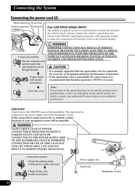
Connecting the power cord (2)<br />
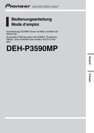
Speed detection circuit lead<br />
Vehicle injection Connector<br />
<strong>com</strong>puter<br />
Pink (CAR SPEED SIGNAL INPUT)<br />
The mobile navigation system is connected here to detect the distance<br />
the vehicle travels. Always connect the vehicle’s speed detection<br />
circuit or the ND-PG1 speed pulse generator, sold separately. Failure<br />
to make this connection will increase errors in the location display.<br />
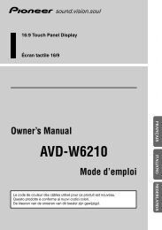
Connection method<br />
Pass the extension cord<br />
and the lead for the<br />
speed detection circuit<br />
through this hole.<br />
Clamp firmly<br />
with needlenosed<br />
pliers.<br />
Close the cover.<br />
IMPROPER CONNECTION MAY RESULT IN SERIOUS<br />
DAMAGE OR INJURY INCLUDING ELECTRICAL SHOCK,<br />
AND INTERFERENCE WITH THE OPERATION OF THE<br />
VEHICLE’S ANTILOCK BRAKING SYSTEM, AUTOMATIC<br />
GEARBOX AND SPEEDOMETER INDICATION.<br />
• It is strongly suggested that the speed pulse wire be connected<br />
for accuracy of navigation and better performance of interlock.<br />
• If the speed pulse wire is unavailable for some reason, it is<br />
re<strong>com</strong>mended that the pulse generator (ND-PG1) be used.<br />
Note:<br />
The position of the speed detection circuit and the position of the<br />
parking brake switch vary depending on the vehicle model. For<br />
details, consult your authorised Pioneer dealer or an <strong>installation</strong><br />
professional.<br />
Light green<br />
Used to detect the ON/OFF status of the handbrake. This lead must be<br />
connected to the power supply side of the handbrake switch.<br />
If this connection is made incorrectly or omitted, certain<br />
functions of your navigation system will be unusable.<br />
LIGHT GREEN LEAD AT POWER<br />
CONNECTOR IS DESIGNED TO DETECT<br />
PARKED STATUS AND MUST BE<br />
CONNECTED TO THE POWER SUPPLY SIDE<br />
OF THE HANDBRAKE SWITCH. IMPROPER<br />
CONNECTION OR USE OF THIS LEAD MAY<br />
VIOLATE APPLICABLE LAW AND MAY<br />
RESULT IN SERIOUS INJURY OR DAMAGE.<br />
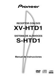
Connection method<br />
Clamp the parking brake<br />
switch power supply side lead.<br />
Power supply side<br />
Earth side<br />
Clamp firmly with<br />
needle-nosed pliers.<br />
Handbrake switch<br />
11