jenn-air® 36" (91.4 cm) accolade™ downdraft ventilation system ...
jenn-air® 36" (91.4 cm) accolade™ downdraft ventilation system ...
jenn-air® 36" (91.4 cm) accolade™ downdraft ventilation system ...

You also want an ePaper? Increase the reach of your titles
YUMPU automatically turns print PDFs into web optimized ePapers that Google loves.
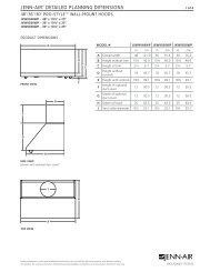
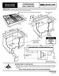
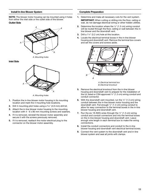
Install In-line Blower System<br />
NOTE: The blower motor housing can be mounted using 4 holes<br />
from either the inlet side or the outlet side of the blower.<br />
Outlet Side<br />
A<br />
A<br />
A<br />
Complete Preparation<br />
1. Determine and make all necessary cuts for the vent <strong>system</strong>.<br />
IMPORTANT: When cutting or drilling into the floor, ceiling or<br />
wall, do not damage electrical wiring or other hidden utilities.<br />
2. Determine the location where the ¹⁄₂" (1.3 <strong>cm</strong>) wiring conduit<br />
will be routed through the floor, ceiling or wall between the inline<br />
blower and the <strong>downdraft</strong> vent.<br />
3. Drill a 1¹⁄₄" (3.2 <strong>cm</strong>) hole at this location.<br />
4. Locate the electrical terminal boxes in the in-line blower<br />
housing and <strong>downdraft</strong> vent. Remove the terminal box covers<br />
and set the covers and screws aside.<br />
A<br />
A. Mounting holes<br />
Inlet Side<br />
B<br />
A<br />
A<br />
A. Mounting holes<br />
1. Position the in-line blower motor housing in its mounting<br />
location and mark the 4 mounting hole locations.<br />
2. Drill 4 mounting pilot holes using a ³⁄₁₆" (4.8 mm) drill bit.<br />
3. Attach the in-line blower motor housing to the mounting<br />
location with 4 - 6 x 80 mm mounting screws and washers.<br />
4. If it is removed, reinstall the blower motor assembly and<br />
secure it with the screws previously removed.<br />
5. If it is removed, reattach the motor electrical plug to the<br />
connector on the blower motor assembly.<br />
A<br />
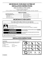
A. Electrical terminal box<br />
B. Electrical knockout<br />
5. Remove the electrical knockout from the in-line blower<br />
housing and <strong>downdraft</strong> vent to prepare for the installation of<br />
the UL listed or CSA approved ¹⁄₂" (1.3 <strong>cm</strong>) wiring conduit and<br />
conduit connector.<br />
6. With the <strong>downdraft</strong> vent mounted, run the ¹⁄₂" (1.3 <strong>cm</strong>) wiring<br />
conduit between the in-line blower motor housing and the<br />
<strong>downdraft</strong> vent. Pull enough ¹⁄₂" (1.3 <strong>cm</strong>) wiring conduit to<br />
allow for easy connection to the terminal boxes in the in-line<br />
blower housing and <strong>downdraft</strong> vent.<br />
7. Run the six 18 AWG wires through the ¹⁄₂" (1.3 <strong>cm</strong>) wiring<br />
conduit and conduit connectors and into the terminal boxes<br />
on the in-line blower housing and <strong>downdraft</strong> vent. Leave<br />
enough wire length in each terminal box to make the wiring<br />
connections.<br />
8. Install the conduit connectors and conduit to the in-line<br />
blower housing and <strong>downdraft</strong> vent electrical terminal boxes.<br />
9. Connect the vent <strong>system</strong> to the <strong>downdraft</strong> vent and in-line<br />
blower <strong>system</strong> and seal all joints with clamps.<br />
11