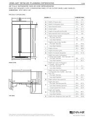
jenn-air® 36" (91.4 cm) accolade™ downdraft ventilation system ...
jenn-air® 36" (91.4 cm) accolade™ downdraft ventilation system ...
jenn-air® 36" (91.4 cm) accolade™ downdraft ventilation system ...

You also want an ePaper? Increase the reach of your titles
YUMPU automatically turns print PDFs into web optimized ePapers that Google loves.
Electrical Requirements<br />
Observe all governing codes and ordinances.<br />
Ensure that the electrical installation is adequate and in<br />
conformance with National Electrical Code, ANSI/NFPA 70 (latest<br />
edition), or CSA Standards C22.1-94, Canadian Electrical Code,<br />
Part 1 and C22.2 No. 0-M91 (latest edition) and all local codes<br />
and ordinances.<br />
If codes permit and a separate ground wire is used, it is<br />
recommended that a qualified electrician determine that the<br />
ground path is adequate.<br />
A copy of the above code standards can be obtained from:<br />
National Fire Protection Association<br />
1 Batterymarch Park<br />
Quincy, MA 02169-7471<br />
CSA International<br />
8501 East Pleasant Valley Road<br />
■<br />
■<br />
■<br />
■<br />
Cleveland, OH 44131-5575<br />
A 120 volt, 60 Hz., AC only, 15-amp, fused electrical circuit is<br />
required.<br />
If the house has aluminum wiring, follow the procedure<br />
below:<br />
1. Connect a section of solid copper wire to the pigtail<br />
leads.<br />
2. Connect the aluminum wiring to the added section of<br />
copper wire using special connectors and/or tools<br />
designed and UL listed for joining copper to aluminum.<br />
Follow the electrical connector manufacturer's recommended<br />
procedure. Aluminum/copper connection must conform with<br />
local codes and industry accepted wiring practices.<br />
Wire sizes and connections must conform with the rating of<br />
the appliance as specified on the model/serial rating plate.<br />
The model/serial plate is located on the front of the <strong>downdraft</strong><br />
vent.<br />
Wire sizes must conform to the requirements of the National<br />
Electrical Code, ANSI/NFPA 70 (latest edition), or CSA<br />
Standards C22. 1-94, Canadian Electrical Code, Part 1 and<br />
C22.2 No. 0-M91 (latest edition) and all local codes and<br />
ordinances.<br />
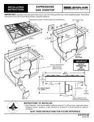
Venting Requirements<br />
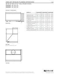
IMPORTANT: Make sure there is proper clearance within the wall<br />
or floor before making exhaust vent cutouts.<br />
■<br />
■<br />
■<br />
■<br />
■<br />
■<br />
■<br />
■<br />
■<br />
■<br />
Use heavy (rigid) metal vent.<br />
Venting <strong>system</strong> must terminate to the outside.<br />
Do not terminate the vent <strong>system</strong> in an attic or other enclosed<br />
area.<br />
Do not use 4" (10.2 <strong>cm</strong>) laundry-type wall caps.<br />
Do not install 2 elbows together.<br />
Do not use plastic or metal foil vent.<br />
The length of vent <strong>system</strong> and number of elbows should be<br />
kept to a minimum to provide efficient performance.<br />
Use no more than three 90° elbows<br />
Make sure there is a minimum of 24" (61 <strong>cm</strong>) of straight vent<br />
between the elbows if more than one elbow is used.<br />
Use clamps or duct tape to seal all joints in the vent <strong>system</strong>.<br />
■ Use caulking tape to seal the exterior wall or floor opening<br />
around cap.<br />
■ Do not cut joist or stud. If vent cutout falls over a joist or stud,<br />
a supporting frame must be constructed.<br />
Flexible metal vent is not recommended. If it is used, calculate<br />
each foot of flexible vent as 2 ft (0.6 m) of rigid metal vent.<br />
Flexible elbows count twice as much as standard elbows.<br />
Recommended Vent System Length:<br />
The vent <strong>system</strong> length should not exceed the maximum lengths<br />
listed in the Maximum Length of Vent System chart. See<br />
“Calculating Vent System Length” in the “Venting Methods”<br />
section in the Installation Instructions for the interior- or exteriormounted<br />
vent motor.<br />
Cold Weather Installations<br />
An additional back draft damper should be installed to minimize<br />
backward cold air flow and a thermal break should be installed to<br />
minimize conduction of outside temperatures as part of the vent<br />
<strong>system</strong>. The damper should be on the cold air side of the thermal<br />
break.<br />
The break should be as close as possible to where the vent<br />
<strong>system</strong> enters the heated portion of the house.<br />
Makeup Air<br />
Local building codes may require the use of makeup air <strong>system</strong>s<br />
when using <strong>ventilation</strong> <strong>system</strong>s greater than specified CFM of air<br />
movement. The specified CFM varies from locale to locale.<br />
Consult your HVAC professional for specific requirements in your<br />
area.<br />
See the “Accessories” section for information on ordering<br />
optional kits.<br />
7