Create successful ePaper yourself
Turn your PDF publications into a flip-book with our unique Google optimized e-Paper software.
USER MANUAL<br />
English<br />
Français<br />
Español
English<br />
.68 Caliber Electronic Paintball Marker<br />
TABLE OF CONTENTS<br />
IMPORTANT SAFETY GUIDELINES 1<br />
OPERATION GUIDE / START UP 2<br />
CO2 / COMPRESSED AIR TANK WARNINGS 3<br />
INSTALLING A CO2 / COMPRESSED AIR TANK 4<br />
PROPER USE OF BARREL BLOCKING DEVICE 4<br />
BATTERY INSTALLATION / OPTIONAL ACCESSORY CHARGING INSTRUCTIONS 5-6<br />
LEAP CIRCUIT BOARD w/CAMD SETTINGS 7<br />
VELOCITY ADJUSTMENT 8<br />
TRIGGER ADJUSTMENT 8<br />
DISASSEMBLE / REASSEMBLE AND CLEANING OF REAR INTERNALS 9-10<br />
A JAMMED PAINTBALL 10<br />
ANTI CHOP EYES / CHANGING BALL STOPPERS 11<br />
CUP SEAL REMOVAL 12<br />
TROUBLESHOOTING 13<br />
AIR LEAKS 14<br />
PILOT w/Eye PARTS LIST 15<br />
PILOT w/Eye SCHEMATIC 16<br />
WARRANTY STATEMENT 17
English<br />
<br />
IMPORTANT SAFETY GUIDELINES<br />
WARNING<br />
• This paintball marker is NOT a toy. It can cause serious injury or death.<br />
• Kingman recommends that the customer be at least 18 years of age to purchase this product.<br />
• Read this manual and air tank warnings before using this product.<br />
• Any modifications or tampering of original factory parts will void all warranties and liabilities<br />
from Kingman.<br />
• Kingman recommends using a barrel blocking device when the marker is not in operation.<br />
• To ensure proper adjustment of velocity Feet Per Second (fps), Kingman strongly recommends<br />
using a chronograph for paintball use located at most paintball stores and paintball fields.<br />
• Before / after use of the marker, make sure to fasten all screws. Screws may become loose due to<br />
vibration. Loose screws can be dangerous and cause injury.<br />
• Kingman STRONGLY recommends that any person using this product or within range of this<br />
product while it is in use MUST wear EYE/FACE PROTECTION designed specifically for the sport<br />
of paintball. This includes, but is not limited to, performing a maintenance check and during target<br />
practice.<br />
• Kingman reminds the user that it is YOUR RESPONSIBILITY to protect your eyes/face at<br />
all times, and will not be held liable for injuries sustained when failing to wear the appropriate<br />
protection.<br />
• Never shoot or point your marker at a person that is not in a designated paintball facility and<br />
without proper paintball EYE/FACE PROTECTION.<br />
• Treat every paintball marker as if it were loaded.<br />
• Never look down the barrel of a loaded or unloaded marker.<br />
• Always keep the paintball marker in SAFE or OFF mode until ready to operate.<br />
• Always remove the gas and all paintballs before disassembly.<br />
• Fire only 0.68 caliber paintballs with this product.<br />
• Always make certain the bolt is in the un-cocked position when marker is not in use.<br />
• Using a paintball marker outside of a non designated paintball field can be illegal, and is<br />
subject to law enforcement penalties if property damage is caused by the user.<br />
• Never point or shoot your marker at an animal.<br />
• Transfer this instruction manual upon change of marker ownership.<br />
OPERATION GUIDE / START UP<br />
1.<br />
2.<br />
3.<br />
4.<br />
5.<br />
6.<br />
7.<br />
8.<br />
9.<br />
10.<br />
11.<br />
12.<br />
13.<br />
WARNING: Always keep the marker powered OFF or on SAFE until you are ready to fire.<br />
Always attach a barrel blocking device over the tip of the barrel for safety precautions when the marker is not in use.<br />
Install and charge the battery see pages (See Battery Installation / Charging).<br />
Attach a CO2 / Compressed Air Tank to the C/A Adapter. HELPFUL TIP: Make sure to have the CO2 /<br />
Compressed Air Tank filled before attaching to the marker. Hand tighten the tank clockwise in the markers<br />
C/A adapter until it is snug. If an air leak occurs between the tank and the C/A adapter, replace the urethane<br />
O-ring. NOTE: O-rings in the markers parts kit are not supplied to attach with a CO2 / Compressed Air Tank.<br />
IMPORTANT: You should never need to use any hand tool to attach a CO2 / Compressed Air Tank to the C/A<br />
adapter.<br />
Attach an electronic paintball loader and elbow to the markers Feed Neck. Only use .68 caliber paintballs<br />
through the electronic loader. NOTE: Kingman recommends that you use a force feed / high speed electronic<br />
loader to reach optimum performance.<br />
Turn Power On for the electronic trigger frame (See LEAP Circuit Board w/CAMD Settings).<br />
Cocking the marker. Pull the Top Cocking Knob rearward until the Delrin Bolt latches. CAUTION: Should you<br />
let go of the Top Cocking Knob before it latches, your marker may fire.<br />
Remove the barrel blocking device. CAUTION: With the power switch turned ON the marker is LIVE. Pulling the<br />
trigger will fire a paintball. IMPORTANT: Only test your marker in a safe direction or in a designated playing field.<br />
Performing a velocity (fps) check. Turning the velocity adjuster & spring guide clockwise will increase the<br />
velocity (fps) while turning counter-clockwise will decrease the velocity (fps). NOTE: Your marker is intended<br />
to be used in a paintball facility with the proper paintball protection. IMPORTANT: Kingman recommends using<br />
a chronograph to ensure that the maker’s velocity is under 300 (fps).<br />
When finished playing, remove all paintballs from the paintball loader before detaching from the markers feed<br />
neck. CAUTION: There may be paintballs in the marker’s breach; take a couple of shots in a safe direction to<br />
make sure the barrel and receiver are empty.<br />
Place the barrel blocking device over the barrel tip. This will help avoid any accidental discharge.<br />
Kingman recommends having the marker in the “SAFE or OFF” position after use.<br />
Unscrew the CO2 / Compressed Air Tank from the marker’s C/A adapter. Firmly hand loosen the tank counterclockwise<br />
to detach it from the marker’s C/A adapter. CAUTION: Never expose any skin underneath the C/A<br />
adapters bleed hole when removing the tank. This can run the risk of getting skin burn from the releasing of<br />
the GAS. IMPORTANT: You should never need to use any hand tool to detach a CO2 / Compressed Air Tank.<br />
Store the marker in a paintball bag or in a safe place. WARNING: Before / after use of the marker, make sure<br />
to fasten all screws. Screws can become loose due to vibration. Loose screws can be dangerous and cause<br />
injury. HELPFUL TIP: It’s a good practice to lubricate your marker before and after each use, especially when<br />
storing the marker for an extended period of time. Add a few drops of paintball gun oil on the Striker O-ring<br />
(see Disassemble / Reassemble). Before storing the marker, make sure the marker is in the un-cocked position.<br />
This will help the main spring maintain its tension.<br />
IMPORTANT<br />
• Firing velocity may vary according to altitude and climate conditions.<br />
• Before using your marker in play, you must always first perform a “SAFE VELOCITY TEST”. This can only be<br />
accomplished by using a testing device called a “Velocity Chronograph“ and can be performed at a paintball<br />
dealership or local playing field. NOTE: This product is intended to be used at a velocity no greater than 300<br />
feet per second (fps). Paintball markers are not intended to shoot any person less then 25 feet away without<br />
EYE/FACE PROTECTION.<br />
• This paintball marker may have excess gas after the removal of the CO2 / Compressed Air Tank. Please<br />
remove all paintballs and discharge the remaining gas safely.<br />
• Never store a CO2 / Compressed Air Tank attached on the marker while not supervised.
English<br />
CO2 / COMPRESSED AIR TANK WARNINGS<br />
SAFE<br />
WARNING:UNSAFE<br />
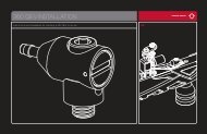
INSTALLING A CO2 / COMPRESSED AIR TANK<br />
Firmly hand tighten the CO2 / Compressed Air Tank clockwise into the markers C/A adapter. HELPFUL TIP: Before<br />
installing a CO2 / Compressed Air Tank, make sure that the tank is full and that it has a urethane bottle o-ring on the<br />
top of the valve to prevent air leaks.<br />
IMPORTANT: You should never need to use any hand tool to attach a CO2 / Compressed Air Tank to the C/A adapter.<br />
REMOVING A CO2 / COMPRESSED AIR TANK<br />
With a firm grip holding the CO2 / Compressed Air Tank remove the cylinder by hand turn counter-clockwise until<br />
it comes out of the C/A adapter. HELPFUL TIP: After firing the marker, you should ALWAYS remove the CO2 /<br />
Compressed Air Tank before storing. When the tank is being removed, excess air will release from the C/A adapter.<br />
CAUTION: Never expose any skin to the C/A adapters bleed hole when removing the tank. This is to avoid the risk of<br />
getting skin burn from the escaping GAS.<br />
IMPORTANT: You should never need to use any hand tool to detach a CO2 / Compressed Air Tank from the C/A<br />
adapter. If you cannot remove a tank by hand please see a certified airsmith for assistance.<br />
CO2 / COMPRESSED AIR TANK WARNINGS<br />
• All valves must only be installed or removed by a qualified airsmith.<br />
•<br />
•<br />
•<br />
•<br />
•<br />
•<br />
•<br />
•<br />
•<br />
•<br />
•<br />
•<br />
•<br />
•<br />
See CO2 / Compressed Air tank labels for retest dates. Cylinder tanks must be retested periodically.<br />
Improper use, filling, storage or disposal of all air cylinders may result in death, personal injury and/or property<br />
damage.<br />
Always keep cylinders out of reach from children or any inexperienced person(s).<br />
Only properly trained personnel in accordance with CGA Pamphlets P.1 and G-6.3 must fill all air cylinders.<br />
Pamphlets are available from the Compressed Gas Association or www.CGANET.com.<br />
Never alter the cylinder in any way.<br />
DO NOT expose pressurized cylinders to temperatures in excess of 130˚F (54˚C).<br />
Cylinders heated to an excess of 250˚F (121˚C) must be condemned or requalified in accordance with test<br />
defined in CFR-49.<br />
The valve should NEVER be detached from the canister. Please seek immediate assistance from a trained<br />
airsmith should this occur.<br />
Any tank packed with the product is intended for paintball use only.<br />
Confirm that there is an attached urethane O-ring on the CO2 / Compressed Air tank valve before attaching<br />
the tank to the marker. The tank will leak air as soon as it is secured to the marker, if the O-ring is missing from<br />
the valve.<br />
DANGER<br />
A urethane O-ring is highly recommended before attaching any air supply to the marker.<br />
NEVER over pressurize a CO2 / Compressed Air cylinder.<br />
The CO2 or Compressed Air Tank can fly off with enough force to cause serious<br />
injury or death if the Valve unscrews from the cylinder head. LOOK at the Valve<br />
when removing the cylinder from the marker. Be sure that the valve is turning<br />
with the cylinder rather than remaining stationary with the marker. STOP if the<br />
Valve starts to unscrew from the cylinder. If in doubt, screw the cylinder back<br />
onto the marker and contact a trained person for repair.<br />
Avoid any direct skin exposure to the escaping gas, when installing or removing any air supply.<br />
Never expose cylinders to corrosive materials or clean with any caustic cleaners.<br />
PROPER USE OF YOUR BARREL BLOCKING DEVICE<br />
A Barrel Blocking Device or “BBD” is an essential part of your paintball safety equipment. The Barrel Blocking<br />
Device is designed to stop a paintball from exiting a paintball marker accidentally. Improper use of the Barrel<br />
Blocking Device will render this device useless.<br />
BARREL SOCK/BAG TYPE DEVICE<br />
Place the bag/sock part of the Barrel Blocking Device over the end of your barrel and wrap the elastic cord around<br />
the back end of your marker.<br />
Adjust the length of the elastic cord to make sure your Barrel Blocking Device fits securely over your markers barrel.<br />
NOTE: If the elastic cord is too long you can tie a couple of knots around the cord to shorten its length.<br />
BARREL PLUG TYPE DEVICE<br />
Insert the barrel plug securely into the end of your markers barrel before proceeding to load paintballs and screwing<br />
in your tank to your marker.<br />
The barrel plug should fit firmly into the barrel with a significant amount of resistance. NOTE: The barrel plug should<br />
not be easy to remove and always inspect the O-rings to make sure they are not worn or cut.<br />
Remove the Barrel Blocking Device only when you are getting ready to begin play or have been instructed to do so<br />
by a field safety official.<br />
Always keep your Barrel Blocking Device on your marker after you have finished playing. Keep it in place even after<br />
you have emptied all paintballs and removed your air tank from your paintball marker.<br />
WARNING<br />
Inspect your Barrel Blocking Device regularly for wear and any tear if it is worn, replace it immediately.<br />
Always have your Barrel Blocking Device in place on your markers barrel to insure safety and prevent accidents that<br />
may cause permanent injury or even death.
English<br />
BATTERY INSTALLATION<br />
SCR002<br />
SCR002<br />
GRP005<br />
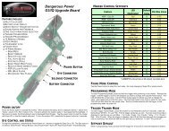
Part Names and Numbers describe in this section:<br />
Dual Texture Grip Panel (#GRP005)<br />
M4 x 8 Screw (A) (#SCR002)<br />
Battery Harness (#WRH002)<br />
WRH002<br />
BATTERY INSTALLATION<br />
NOTE: This marker is compatible with the use of 9volt Alkaline batteries. Use only premium brand Alkaline batteries<br />
for best performance. (Battery Not Included)<br />
Shot counts will vary depending on the type of 9volt Alkaline battery used (2300 to 3200), choosing a premium<br />
brand battery will give the best results.<br />
Kingman Group recommends using a Spyder 9.6volt NiMH Rechargeable Battery as a power source for optimum<br />
performance and will provide a superior shot count of around 5000 to 6000 rounds. (Spyder Battery and Charger<br />
Sold Separately)<br />
IMPORTANT: Performance will vary depending on the mode used and rate of fire achieved.<br />
STEP 1 Remove the three M4x8 Screws from the Right side grip panel. NOTE: Allen wrench provided in the<br />
spare parts kit.<br />
STEP 2 Attach the battery to the battery harness.<br />
STEP 3 Re-tighten the three M4x8 Screws.<br />
HELPFUL TIP: Please note how the parts are removed for easy reassembly.<br />
CHARGING INSTRUCTIONS<br />
Spyder 9.6volt Battery (US LED) optional accessory<br />
To charge a Spyder 9.6 NiMH battery, the circuit board must be in the OFF position. Spyder batteries (JE1015) are not<br />
fully charged when purchased. Using the supplied Spyder LED A/C Charger (JE1029), plug the charger into the charger<br />
port located at the rear of the trigger frame. For a complete charge, Kingman recommends a charging time of 6-8 hours.<br />
STEP 1 Plug the Spyder LED A/C charger into a power outlet.<br />
STEP 2 Connect the Spyder A/C charger cord to the rear of the markers trigger frame’s charging port.<br />
STEP 3 The LED indicator on the Spyder LED A/C charger will display RED when the battery is charging.<br />
STEP 4 The LED indicator on the Spyder LED A/C charger will display GREEN when the battery is fully charged.<br />
STEP 5 Unplug the Spyder LED A/C charger cord from the rear of the markers trigger frame’s charging port after<br />
charging.<br />
STEP 6 Remove the Spyder LED A/C charger from the power outlet.<br />
IMPORTANT: Never charge the battery for over 24 hours, as you will risk damaging the battery and/or electronics.<br />
HELPFUL TIP: It is recommended that the battery be charged prior to use in order to ensure maximum performance,<br />
especially if the battery has not been used in over a week. NOTE: A fully charged Spyder battery will last about<br />
5000-6000 shots, depending on your firing methods or firing mode in use. Under normal use and charging<br />
conditions the expected life of the Spyder battery is approximately 700-1000 charging cycles.<br />
To avoid any risks of having the Battery explode or the Circuit Board burned: charge only Spyder 9.6volt NiMH<br />
Batteries in Spyder electronic frames.<br />
IMPORTANT<br />
• DO NOT attempt to recharge any Alkaline or any other type of battery in the Spyder electronic frame.<br />
• DO NOT try to recharge batteries that are rusted, corroded, damaged or leaking.<br />
• FAILURE to follow any of the instructions will VOID ALL WARRANTIES AND LIABILTIES from Kingman.<br />
Kingman will not be held liable for any injury or damages from the improper use of this product. This accessory is not<br />
intended for use with any other product other than what Kingman designed it for.<br />
Spyder 9.6volt Battery (EU) optional accessory<br />
To charge a Spyder 9.6 NiMH battery, the circuit board must be in the OFF position. Spyder batteries (JE1015) are<br />
not fully charged when purchased. Using the supplied A/C Charger (JE1025), plug the charger into the charger port<br />
located at the rear of the trigger frame. For a complete charge, Kingman recommends a charging time of 6-8 hours.<br />
IMPORTANT: Never charge the battery for over 24 hours, as you will risk damaging the battery and/or electronics.<br />
HELPFUL TIP: It is recommended that the battery be charged prior to use in order to ensure maximum performance,<br />
especially if the battery has not been used in over a week.<br />
NOTE: A fully charged Spyder battery will last about 5000-6000 shots, depending on your firing methods or firing<br />
mode in use. Under normal use and charging conditions the expected life of the Spyder battery is approximately<br />
700-1000 charging cycles.<br />
To avoid any risks of having the Battery explode or the Circuit Board burned: charge only Spyder 9.6volt NiMH<br />
Batteries in Spyder electronic frames.<br />
IMPORTANT<br />
• DO NOT attempt to recharge any Alkaline or any other type of battery in the Spyder electronic frame.<br />
• DO NOT try to recharge batteries that are rusted, corroded, damaged or leaking.<br />
• FAILURE to follow any of the instructions will VOID ALL WARRANTIES AND LIABILTIES from Kingman.<br />
Kingman will not be held liable for any injury or damages from the improper use of this product. This accessory is not<br />
intended for use with any other product other than what Kingman designed it for.
English<br />
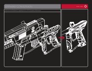
LEAP CIRCUIT BOARD w/CAMD SETTINGS<br />
SAFE – Red LED<br />
SEMI – Green LED<br />
RAMP P – Blue LED (PSP RAMP) 13 Balls Per Second<br />
RAMP M – Blue LED (Millennium RAMP) 12 Balls Per Second<br />
EYE<br />
BATTERY<br />
– Orange LED (LED ON = Eyes ON, LED OFF = Eyes OFF)<br />
– Yellow LED (Solid LED = Good, Flashing LED = Low)<br />
CAMD Display<br />
UPPER Button<br />
LOWER Button<br />
TRIGGER ADJUSTMENT<br />
SCR029<br />
2 Button Access Operations<br />
Press and release the Upper “Power/Eye” Button to turn the marker “On”. The CAMD will display the Red “Safe”<br />
indicator “On” meaning that the marker is in safety mode and will not allow the marker to shoot. The default firing<br />
mode is Semi Auto and the Green “Semi” indicator will be displayed as the marker firing mode.<br />
To turn the safety “Off” press and release the Lower “Mode” Button and the Red “Safe” indicator will turn off, the<br />
marker is now capable of firing in Semi Auto. To turn the safety back “On” press and release the Lower “Mode”<br />
Button again.<br />
To turn the Power “Off” press and hold the Power Button until all CAMD LED indicator powers down completely.<br />
Changing Modes<br />
To change the firing mode, Press and hold the Lower “Mode” Button until the firing mode indicator on the CAMD<br />
start flashing. While the indicator is flashing press and release the Lower “Mode” Button to scroll through the mode<br />
setting. When the desired firing mode has been selected, press and hold the Lower “Mode” Button until the indicator<br />
stops flashing. The marker will now operate in the firing mode that has been selected. The Red “Safe” indicator will<br />
remain “On”, to turn the safety “Off” press and release the Lower “Mode” Button and the Red “Safe” indicator will<br />
turn “Off”, the marker is now capable of firing in the selected mode. NOTE: When the Power is turned “Off” the firing<br />
mode will default back to Semi Auto if the Firing Mode Lock feature is not used.<br />
(Refer to Firing Mode Lock section)<br />
IMPORTANT: The safety may be enabled in any mode by pressing and releasing the Lower “Mode” Button, the Red<br />
“Safe” LED indicator will turn on and keep the marker from accidentally shooting while the Power is “On”.<br />
Firing Mode Lock<br />
To lock the operations of the marker in Semi-Auto Mode remove the lock switch from the circuit board while the<br />
Power is “Off” this will default the marker operation and shoot in Semi-Auto Mode Only.<br />
To lock the operation in Ramp P (PSP) Mode turn the marker Power “ON”, select Ramp P on the CAMD indicator,<br />
remove the tournament lock switch from the circuit board to lock in Ramp P Mode. NOTE: Following the same steps<br />
on selecting the Ramp P Mode will allow you to lock the marker operation in Ramp M (Millennium) mode. NOTE: Use<br />
the lock switch when the playing field requires it.<br />
Anti Chop Eye Operation<br />
To turn off the Anti Chop Eye feature press and release the Upper “Power/Eye” Button, the “Orange” Eye indicator<br />
will turn off indicating that the eyes are off. NOTE: This feature is useful if you need to cycle the marker without<br />
paintballs for a clearing shot.<br />
To turn the eyes back on press and release the Top “Power/Eye” Button again and the Eye indicator will light back<br />
up indicating that the eyes are on. NOTE: Semi-Auto mode maybe the only allowable firing mode permitted in your<br />
country. Check with your local officials regarding this application. For example select European countries, Australia<br />
and New Zealand are restricted to use Semi-Auto model only.<br />
NOTE: European Edition “Semi-Auto Mode Only”<br />
WARNING<br />
• Spyder Electronic Markers are not water resistant.<br />
• Extreme moisture can cause serious damage to any Spyder Electronic Marker.<br />
• Always clean any dirt or paint inside the markers electronics.<br />
• Never attempt to modify the electronics circuitry, doing so will VOID all electronic warranties and<br />
liabilities from Kingman.<br />
Magnetic Response “Saber” Trigger<br />
There are 3 adjuster set screws that allows the adjustment for the trigger pull, the micro switch actuation, a post<br />
travel stop and the magnetic response strength.<br />
The first set screw furthest from the micro switch is for adjusting the amount of resistance force the magnet applies<br />
on the trigger. Adjusting the set screw in will increase resistance and out will reduce it for a lighter trigger pull.<br />
The middle set screw is for adjusting the distance between the trigger and the micro switch. Adjusting the set screw<br />
in will bring the trigger actuation closer giving the trigger a short trigger pull.<br />
HELPFUL TIP: Remember not to over adjust this set screw as you may have the trigger rest against the micro<br />
switch and not allow the micro switch to reset for the next trigger pull.<br />
The third set screw, closest to the micro switch, is for the post travel of the trigger. It is to stop the trigger from<br />
further back travel after it has actuated the micro switch<br />
VELOCITY ADJUSTMENT INCREASE / DECREASE<br />
To INCREASE your velocity fps using the Allen wrench, turn the Velocity Adjuster / Spring Guide clockwise.<br />
To DECREASE your velocity fps using the Allen wrench, turn the Velocity Adjuster / Spring Guide counterclockwise.<br />
NOTE: Allen wrench provided in the spare parts kit. NOTE: Velocity Adjuster / Spring Guide doesn’t<br />
remove from the rear of the Sticker Plug. NOTE: The velocity of this paintball marker ranges from approximately<br />
240 - 300 feet per second (fps). Velocities will fluctuate or vary due to paintball size, climate condition, altitude,<br />
type of air source and variance in spring tension from manufacturing.<br />
WARNING<br />
•<br />
•<br />
•<br />
•<br />
•<br />
VTA026<br />
VTA027<br />
STP026<br />
STP027<br />
The recommended Velocity speed should be no greater then 300 fps. Not doing so can cause serious injury or death<br />
if the velocity is set dangerously high.<br />
Paintball markers are not intended to shoot any person less then 25 feet away without eye/face protection.<br />
Never point a loaded marker at any person who is not wearing the proper face protection.<br />
Never at any point should you look down the barrel, whether the marker is loaded or not.<br />
Using a paintball marker outside a non designated paintball field can be illegal, and is subject to law<br />
enforcement penalties if property damage is caused by the user.
English<br />
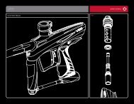
DISASSEMBLE / REASSEMBLE AND CLEANING OF REAR INTERNALS<br />
REASSEMBLY REAR INTERNALS<br />
CONNECTED<br />
DISCONNECTED<br />
VBT008<br />
STK008<br />
STF001<br />
REC026<br />
REC027<br />
ORG001<br />
Part Names and Numbers describe in this section:<br />
Striker O-ring (#ORG001)<br />
Receiver (#REC026/REC027)<br />
Striker Spring (#SPR004)<br />
Striker Bolt (#STB002)<br />
Striker Buffer (#STF001)<br />
STB002<br />
SPR004<br />
VTA026<br />
VTA027<br />
Striker Plug (#STP026/STP027)<br />
Top Cocking Knob (#STK008)<br />
Delrin Bolt (#VBT008)<br />
Velocity Adjuster/Spring Guide (#VTA026/VTA027)<br />
QUICK CLEAN DISASSEMBLY<br />
Lift upward on the Top Cocking Knob to disconnect the Delrin Bolt from the Striker Bolt. This will allow the Delrin Bolt to slide<br />
out from the rear of the Receiver. HELPFUL TIP: Removing the Delrin Bolt from the Receiver will allow easy access<br />
to clean with a squeegee. NOTE: Make sure the hole on the Striker Bolt is facing upright when looking thru the<br />
Receiver. This will allow the Top Cocking Pin to correctly fasten with the Striker Bolt.<br />
IMPORTANT: The air passage hole located in the middle of the Delrin Bolt should always be facing downward when<br />
reinstalling. If the Delrin Bolt is not installed correctly, paintballs will not exit out of the barrel normally.<br />
DISASSEMBLE OF REAR INTERNALS<br />
STEP 1 Lift upward on the Top Cocking Knob to disconnect the Delrin Bolt from the Striker Bolt. This will allow the<br />
Delrin Bolt to slide out from the rear of the Receiver.<br />
STEP 2 Using an adjustable wrench (provided in the spare parts kit) turn the Striker Plug counter clockwise located<br />
at the rear of the Receiver. This will allow all internal parts such as the Velocity Adjuster & Spring Guide, Striker<br />
Spring, Striker Buffer and Striker Bolt to slide from the rear of the Receiver. NOTE: Remove the Striker Plug only<br />
with the marker in the un-cocked position this will prevent the internals from springing out because the Striker<br />
Spring is compressed. HELPFUL TIP: Placing your finger behind the Striker Plug before removing this will prevent<br />
the markers internals from springing out.<br />
STEP 3 Remove items in order; Striker Plug w/Velocity Adjuster, Striker Spring and Striker Buffer.<br />
STP026<br />
STP027<br />
STEP 4 Slide the Striker Bolt out of the rear of the Receiver. HELPFUL TIP: When the internals are removed it<br />
would be wise to clean any dirt or paint from the inside of the Receiver with a squeegee and wipe the Delrin Bolt<br />
clean with a rag or paper towel. Apply some paintball gun oil on Striker O-ring periodically.<br />
IMPORTANT: It is not necessary to disassemble the rear internals for basic maintenance unless the Striker O-ring<br />
needs to be replaced.<br />
STEP 1 Reinsert the Striker Bolt with Striker O-ring facing toward the front of the marker with the flat spot of the<br />
Striker Bolt facing down. NOTE: Having the Power Switch ON will ease reentry of the Striker Bolt. Apply thumb<br />
pressure behind the Bolt and at the same time pull on the Trigger. Repeat this process until the Bolt is fully inserted.<br />
NOTE: The hole on the Striker Bolt should be facing upright when looking thru the Receiver. NOTE: The images<br />
above display the Delrin Bolt “connected” to and “disconnected” from the Striker Bolt.<br />
STEP 2 Insert the Striker Buffer flush with the receiver and place the Striker Spring thru the Striker Buffer.<br />
STEP 3 Tighten firmly the Striker Plug w/Velocity Adjuster & Spring Guide to the rear of the Receiver.<br />
STEP 4 Insert the Delrin Bolt thru the rear of the Receiver with the Top Cocking Pin. Press downward on the Top<br />
Cocking Pin to gain entry with the Striker Bolt. NOTE: If the Striker Bolt hole is not aligned upright, the Top Cocking<br />
Pin will not fasten correctly.<br />
WARNING: Before/after use of the marker, make sure to fasten all screws. Screws may become loose due to<br />
vibration. Loose screws can be dangerous and cause injury.<br />
To assure that the marker is assembled properly, follow the schematic drawing or position parts in order during<br />
disassembly. Parts assembled backwards or improper parts installed will/can cause the marker to malfunction.<br />
A JAMMED PAINTBALL IN THE BREACH<br />
In the event of a paintball break and the Delrin Bolt jams, follow these steps to help un-jam the marker. The markers<br />
breach is located where the barrel starts to thread in the receiver and underneath the markers feed neck. Before<br />
attempting to un-jam the Delrin Bolt you should always have your Goggles or Safety Glasses on. Make sure the<br />
marker is in the SAFE / OFF position before attempting to un-jam the Delrin Bolt. Remove the CO2 / Compressed<br />
Air Tank before attempting to un-jam the marker. Remove all paintballs and the loader from the feed neck. Have the<br />
barrel removed from the receiver to allow the paintball (s) to exit. With enough force on the Cocking Knob, pull back<br />
to release the Delrin Bolt from the jammed position. Another method is to use a “Straight Shot Squeegee” or the end<br />
of a wood dowel rod; push against the face of the Delrin Bolt with enough force to release the jammed Bolt. Always<br />
clean the paint from the breach and barrel to enhance the performance of your marker.<br />
IMPORTANT: Never look down the barrel of the marker when loaded or unloaded. Remove the attached CO2 /<br />
Compressed Air Tank before attempting to un-jam the Delrin Bolt.<br />
NOTE: Never use a metal rod or screwdriver as a tool to push on the Delrin Bolt, anything metal will scratch and<br />
damage the inside of the marker.<br />
10
English<br />
ANTI CHOP EYES<br />
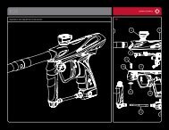
CUP SEAL REMOVAL<br />
BLS003<br />
BLS007<br />
BLS008<br />
ITP012<br />
SCR002<br />
WRH008<br />
LPC026<br />
LPC027<br />
ITP011<br />
SPR013<br />
ITP017<br />
Part Names and Numbers describe in this section:<br />
Eye Panel (#BLS007/BLS008)<br />
Ball Stopper (#BLS003)<br />
Eye Panel Screw (#SCR002)<br />
Eye Wire Harness (#WRH008)<br />
ANTI CHOP EYES<br />
The Anti Chop Eyes help prevent the chopping of paint by not allowing the marker to fire until a paintball is properly<br />
chambered in the breach. The Eyes transmit a beam across the inside of the breech. The circuit board is preset from<br />
the factory and does not need to be adjusted or altered. (If the Eyes are ON and do not see each other when firing<br />
your marker, you will have to clean the Eyes.) NOTE: The Anti Chop Eyes system reduces the likelihood of chopping<br />
paintballs but do not completely eliminate it from happening, keep the Anti Chop Eyes clean for best and reliable<br />
performance.<br />
CLEANING THE ANTI CHOP EYES<br />
Using a squeegee or swab thru the breech should clean the Eyes enough for the Eyes to detect each other. Another<br />
way is to use an aerosol can of air thru the breech to remove any paint or dirt. To thoroughly clean the Eyes using<br />
the supplied Allen wrench remove both Eye Panel Screws and Eye Panels . Once the Eye Panel Screws & Eye<br />
Panels are removed, proceed with a soft pinch to remove the Eye Wire Harness from the receiver. Use a cloth or<br />
paper towel to remove any paint or dirt that is blocking the Eyes.<br />
IMPORTANT: Cleaning the Eyes often will help reduce dirt, paint or oil residue that blocks the Eyes<br />
NOTE: Never attempt to rush the cleaning process or you can pinch the wires and cause the marker to malfunction<br />
with the Eye Mode ON. Take precaution not to over tighten the Eye Panel Screws or this can lead to stripping the<br />
head. NOTE: When the Eye Panels are removed the Ball Stopper(s) may be attached to the Eye Panels and can<br />
cause them to fall out. HELPFUL TIP: Please note how the parts are removed for easy reassembly.<br />
IMPORTANT: Before removing both Eye Panels use a needle or dental pick through the hole of the Eye Panel to<br />
remove any dirt that may have built up and prevent the Allen wrench from loosening the screw. It’s possible if the<br />
dirt is not removed you can strip the Eye Panel Screw.<br />
NOTE: Maintenance cleaning of the Anti Chop Eyes should only be done if a paintball break in the breach has<br />
occurred and affected the detection of the paintballs. Removing the Delrin Bolt and pushing a swab type squeegee<br />
through the breach may be adequate in cleaning the Anti Chop Eyes.<br />
CHANGING THE BALL STOPPERS<br />
Experiencing paint rolling through the barrel can be related to small diameter paintballs or the loss of a Ball<br />
Stopper(s) . When removing Eye Panel Screws and Eye Panels the Ball Stopper(s) will be accessible for cleaning or<br />
replacement.<br />
HELPFUL TIP: Please note how the parts are removed for easy reassembly.<br />
IMPORTANT: Before removing both Eye Panels use a needle or dental pick thru the hole of the Eye Panel to remove<br />
any dirt that can build up and block the Allen screw from loosing. It’s possible if the dirt is not removed you can stripe<br />
the Eye Panel Screw.<br />
NOTE: Take precaution not to over tighten the Eye Panel Screws or this can strip the head. NOTE: Maintenance is<br />
not required for the Ball Stoppers unless they have completely worn out or is unable to keep a paintball from rolling<br />
out the breach of the marker when the marker is pointed down.<br />
Part Names and Numbers describe in this section:<br />
Foregrip Expansion Chamber (#FRG026/FRG027)<br />
Cup Seal Guide (#ITP011)<br />
Cup Seal (#ITP012)<br />
Valve Pin (#ITP017)<br />
M5x20 Vertical Washer (# ITP019)<br />
Front Plug (#LPC026/LPC027)<br />
Valve Spring (#SPR013)<br />
Vertical Adapter (#VRT026/VRT027)<br />
Vertical Adapter Mounting Screw (#SCR027)<br />
STEP BY STEP CUP SEAL ACCESS<br />
Access of the cup seal for service or replacement requires the removal of the Front Plug and Vertical CA Adapter.<br />
STEP 1 Unscrew the Foregrip Expansion Chamber from the Vertical CA Adapter.<br />
STEP 2 Remove the Vertical CA Adapter by unscrewing the Vertical CA Adapter Mounting Screw, be sure to keep a<br />
finger over the Front Plug to prevent it from springing out. NOTE: The Front Plug and Vertical CA Adapter are both<br />
held in place by the Vertical CA Adapter Mounting Screw.<br />
STEP 3 Pull the Front Plug out and it should come out with the Valve Spring, Cup Seal Guide, Cup Seal and Valve<br />
Pin all together.<br />
STEP 4 Unscrew the Cup Seal from the Valve Pin and replace with the spare provided with your spare parts kit.<br />
STEP 5 Follow the previous steps in reverse to re-install all components properly. Make sure the Front Plug screw<br />
hole is lined up with the vertical adapter screw hole.<br />
IMPORTANT: Always make sure all air sources have been removed from your marker and any residual air has been<br />
vented out completely before servicing your marker.<br />
NOTE: Service or replacement of the Cup Seal should only be done if a leak is present and can be heard from the<br />
breach after the removal of the Delrin Bolt.<br />
11 12<br />
FRG026<br />
FRG027<br />
ITP019<br />
VRT026<br />
VRT027<br />
SCR027
English<br />
TROUBLESHOOTING<br />
ONE OR MORE OF THE FOLLOWING MAY CAUSE RECOCKING RELATED ISSUES:<br />
• Need lubrication on the following O-ring (#ORG001) (see Disassemble / Reassemble).<br />
• The pressure in the tank is too low and possibly needs to be refilled.<br />
• Striker O-ring (#ORG001) is damaged or missing. Replace with a new Kingman approved Striker O-ring.<br />
•<br />
•<br />
NOTE: The Striker O-ring can not be substituted with a black or urethane bottle o-ring.<br />
Dirt or broken paint shell fragments in the receiver can cause the marker to have recocking issues. Using a<br />
squeegee thru the upper portion of the receiver will remove most of the dirt or broken shell fragments. Should<br />
this issue continue, (see Disassemble / Reassemble) remove the markers internals for complete cleaning.<br />
Using low quality paintballs can cause the marker to experience recocking issues because of the shape of<br />
the paintballs. HELPFUL TIP: Paintballs have a shelf life and can become too fragile for use. HELPFUL TIP:<br />
Paintballs can take a different shape over time, so it would be wise to size the paintball with your barrel.<br />
ELECTRONIC TRIGGER FRAME TROUBLESHOOTING<br />
• If your marker is not shooting it may be due to one of the following problems:<br />
• Battery may need to be recharged.<br />
• The Battery Wire Harness is not properly attached to the circuit board.<br />
• The Coil Set Harness is not properly attached to the circuit board.<br />
• The Touch Switch Harness is not properly attached to the circuit board. NOTE: If the Markers Electronics<br />
have any dirt or paint, Kingman recommends using an aerosol can of air. Apply the can of air directly at the<br />
components that need cleaning.<br />
AIR LEAKS<br />
IMPORTANT: Always remove the air tank and paintballs before any disassembly of the marker.<br />
• Air leaking from the Front Plug means the O-ring (#ORG002) will need to be oiled or replaced.<br />
• Air leaking from the Vertical Adapter means the O-ring (#ORG023) will need to be oiled or replaced.<br />
• Air leaking down the barrel is usually caused by a worn or damaged cup seal (#ITP012). (see Cup Seal<br />
Removal) should the cup seal need to be exchanged.<br />
• Never remove Valve Body (#ITP018) unless specific repairs are needed.<br />
• A nick or scratch on the lip of the Valve Body can cause an internal air leak (see Cup Seal Removal). The Valve<br />
Body may need to be replaced.<br />
• Air leaking thru the Receiver and out of the Trigger Frame would indicate the Valve Body O-rings (#ORG002)<br />
will need to be replaced.<br />
• If air is leaking thru the opposite end of the hose fittings, please check the following:<br />
• The female end of the hose must have a plastic washer (#HSF004) installed inside the hose collar and be<br />
tightened properly.<br />
IMPORTANT: The hose line supplied has metric female ends. This will not install into American 1/8” (NPT) threaded<br />
fittings. If installed incorrectly, it is possible to damage the attachment fittings and hose line.<br />
HELPFUL TIP: To assure marker is assembled properly, follow the schematic drawing or position parts in order<br />
during disassembly. Parts assembled backwards or improper parts installed will / can cause the marker to<br />
malfunction.<br />
13 14
PILOT w/Eye PARTS LIST<br />
ASA026 C/A Adapter (fine matte black)<br />
ASA027 C/A Adapter (fine matte red)<br />
BAR026 1PCS Barrel (fine matte black)<br />
BAR027 1PCS Barrel (fine matte red)<br />
BLS003 Ball Stopper<br />
BLS007 Aluminum Eye Panel - right (black)<br />
BLS008 Aluminum Eye Panel - left (black)<br />
BLS009 Ball Stopper / Eye Wire Insert - right (black)<br />
BLS010 Ball Stopper / Eye Wire Insert - left (black)<br />
ECB008 LEAP Circuit Board w/CAMD<br />
ELM001 Coil Set<br />
ELM002 Coil Pin<br />
ELM003 Tournament Lock Switch<br />
ELM004 Capacitor<br />
ELM008 LEAP Touch Switch Membrane<br />
FND026 Feed Neck (fine matte black)<br />
FND027 Feed Neck (fine matte red)<br />
FRG026 Foregrip Expansion Chamber (fine matte black)<br />
FRG027 Foregrip Expansion Chamber (fine matte red)<br />
GRP005 Dual Texture Grip Panel (black)<br />
HSE009 Disconnect Hose (male x female)<br />
HSF001 Air Filter<br />
HSF004 Plastic Washer<br />
HSF009 90d Male to Male Adapter (STD x MET)<br />
ITP011 Cup Seal Guide<br />
ITP012 Cup Seal<br />
ITP017 Valve Pin (slim)<br />
ITP018 Valve Body (blind hole)<br />
ITP019 M5x20 Vertical Washer<br />
LPC026 Front Plug (fine matte black)<br />
LPC027 Front Plug (fine matte red)<br />
ORG001 Striker O-ring #14.3 1.7 60pu<br />
ORG002 O-ring #15 80<br />
ORG003 Barrel O-ring #22 1.5 80<br />
ORG004 O-ring #11 80<br />
ORG008 O-ring #10 80<br />
ORG019 O-ring #09 80<br />
ORG023 Vertical O-ring #17 1.5 80<br />
* PAK004<br />
REC026<br />
REC027<br />
RPN001<br />
RPN002<br />
SCR002<br />
Spare Parts Kit<br />
Pilot w/Eye Reeceiver (fine matte black)<br />
Pilot w/Eye Reeceiver (fine matte red)<br />
Sear Roll Pin<br />
Trigger Roll Pin<br />
M4 x 8 Screw (A)<br />
SCR003 Circuit Board Screw (+)<br />
SCR007 M8 x 8 Valve Body Screw (A)<br />
SCR011 Coil Set Screw<br />
SCR024 M5 x 25 C/A Adapter Screw (A)<br />
SCR027<br />
SCR028<br />
SCR029<br />
SER001<br />
SPR004<br />
SPR009<br />
SPR013<br />
STB002<br />
STF001<br />
STK008<br />
STP026<br />
STP027<br />
TRF008<br />
TRS008<br />
VBT003<br />
VBT004<br />
VBT008<br />
VBT013<br />
VRT026<br />
VRT027<br />
VTA026<br />
VTA027<br />
WRH002<br />
WRH007<br />
WRH008<br />
M5 x 20 Vertical Screw (A)<br />
M5 x 10 Trigger Frame Screw (A)<br />
M4 x 6 Trigger Adjustment Screw (A)<br />
Sear<br />
Striker Spring<br />
ESP Sear Spring<br />
Valve Spring<br />
Striker Bolt<br />
Striker Buffer<br />
Top Cocking Knob<br />
Striker Plug Threaded (fine matte black)<br />
Striker Plug Threaded (fine matte red)<br />
Electronic Trigger Frame (PA)<br />
Magnetic Saber Trigger (black)<br />
Delrin Bolt Locking Bearing<br />
Delrin Bolt Locking Spring<br />
Delrin Bolt w/ Locking Knob<br />
Delrin Bolt Locking Screw<br />
Vertical Adapter (fine matte black)<br />
Vertical Adapter (fine matte red)<br />
Velocity Adjuster & Spring Guide (fine matte black)<br />
Velocity Adjuster & Spring Guide (fine matte red)<br />
Battery Harness<br />
Touch Switch (3P)<br />
Eye Wire Harness (xtra long)<br />
PILOT w/Eye SCHEMATICS<br />
VBT008<br />
FND026<br />
FND027<br />
VBT013<br />
VBT004<br />
VBT003<br />
STK008<br />
ORG002<br />
ORG003<br />
ORG001<br />
REC026<br />
REC027<br />
STP026<br />
STP027<br />
ORG002<br />
STF001<br />
ORG008<br />
VTA026<br />
VTA027<br />
SPR004<br />
STB002<br />
BLS009<br />
BLS010<br />
BLS003<br />
SER001<br />
WRH008<br />
SCR007<br />
ORG023<br />
ITP018<br />
ORG002<br />
ITP017<br />
SCR002<br />
BLS007<br />
BLS008<br />
SCR028<br />
SCR002<br />
VRT026<br />
VRT027<br />
SCR029<br />
TRS008<br />
GRP005<br />
SCR028<br />
TRF008<br />
SCR027<br />
ITP019<br />
FRG026<br />
FRG027<br />
RPN002<br />
ELM003<br />
SCR003<br />
WRH007<br />
RPN001<br />
ASA026<br />
ASA027<br />
HSF001<br />
ORG019<br />
ORG004<br />
HSE009<br />
HSF004<br />
SCR011<br />
ELM001<br />
ELM002<br />
ELM004<br />
SCR003<br />
ECB008<br />
English<br />
SCR024<br />
ITP012<br />
ITP011<br />
ORG002<br />
HSF009<br />
SPR013<br />
Charging Port<br />
BAR026<br />
BAR027<br />
ORG002<br />
LPC026<br />
LPC027<br />
CAMD Display<br />
UPPER Button<br />
ELM008<br />
LOWER Button<br />
* Item Not Pictured (+) Cross-head Screw (A) Allen-head Screw<br />
15 16
WARRANTY STATEMENT<br />
Kingman warrants the original retail purchaser that this product is free from defects in material and<br />
workmanship under normal use and service for a period of (1) year from the original date of purchase.<br />
Any Electronic Components in an Electronic Spyder marker are warranted for (6) months from the<br />
original date of purchase. Kingman agrees to repair or replace (at its discretion) any product within (a<br />
reasonable period of time). This warranty does not cover o-rings, cup seals, 9.6v rechargeable battery,<br />
charger, scratches, nicks, normal wear and tear of parts, any modifications, normal fading of anodizing<br />
and damage caused by dropping or hitting of products. This warranty shall not apply if it is shown by<br />
a Kingman Technician that the consumer caused the defect or malfunction because of misuse. This<br />
warranty only covers original factory parts. Any modifications or tampering of original factory parts<br />
will VOID warranty and liabilities from Kingman. Any damage caused by water will not be covered<br />
under warranty. Warranty repair can only be conducted by Kingman technician or Kingman authorized<br />
technician. For warranty to be effective, consumer must return the enclosed warranty registration card<br />
filled out, along with a copy of the purchase receipt, within (15) days of the original purchase date.<br />
This warranty is not transferable. Paintball markers are non-refundable. This warranty will not cover<br />
pick up, shipping, delivery, and/or house calls. If the product needs repair, the consumer is responsible<br />
for packaging the product and covering the shipping cost to Kingman. Please include a note with your<br />
name, address, phone number and a brief description of the malfunction to:<br />
KINGMAN GROUP<br />
Attn: Tech Department<br />
14010 Live Oak Avenue<br />
Baldwin Park, CA 91706 U.S.A.<br />
www.kingman.com<br />
» Warranty Registration is also available at www.spyder.tv<br />
FOR TECHINICAL SUPPORT<br />
Our Technical Support Department is open Monday through Friday, from 8am to 5pm (PST), and can be<br />
reached at Tele: (626) 430-2300 Fax: (626) 851-8530<br />
www.spyder.tv<br />
17
Français<br />
Marqueur Electronique De Paintball De Calibre .68<br />
TABLE DES MATIERES<br />
IMPORTANTES CONSIGNES DE SECURITE 21<br />
MISE EN ROUTE 22<br />
CONSIGNE DE SECURITE SUR LA BOUTEILLE DE CO2/AIR COMPRIME 23<br />
INSTALATION DE LA BOUTEILLE DE GAZ 24<br />
UTILISATION APPROPRIEE DU BOUCHON DE CANON 24<br />
INSTALLATION DE LA PILE / CHARGEMENT DE LA PILE EN OPTION 25-26<br />
REGLAGES DE LA CARTE ELECTRONIQUE « LEAP » AVEC ECRAN « CAMD » 27<br />
REGLAGE DE LA VELOCITE 28<br />
REGLAGE DE LA DETENTE 28<br />
DEMONTAGE/REMONTAGE ET NETTOYAGE DES PIECES INTERIEURES ARRIERES 29<br />
COINCAGE DE BILLE 30<br />
CAPTEURS ANTI CASSE DE BILLE / CHANGEMENT DES « ANTI DOUBLE FEED » 31-32<br />
DEMONTAGE DU “CUP SEAL” 32<br />
GUIDE DES PANNES 33<br />
FUITES D’AIR 34<br />
LISTE DES PIECES DU PILOT with Eye 35<br />
SCHEMA ECLATE DU PILOT with Eye 36<br />
POLICE DE GARANTIE 37
Français<br />
IMPORTANTES CONSIGNES DE SECURITE<br />
ATTENTION<br />
IMPORTANTES CONSIGNES DE SECURITE / MISE EN ROUTE<br />
ATTENTION: Toujours garder son lanceur éteint ou sur le mode “safe” jusqu’a son utilisation.<br />
• Ce lanceur de paintball n’est pas un jouet, il peut provoquer des blessures grave voir la mort.<br />
• Kingman recommande que le client soit agé d’au moins 18 ans pour acheter ce produit.<br />
• Lisez le manuel attentivement et les précautions d’emploi de la bouteille d’air avant d’utiliser ce produit.<br />
• Toute modification du produit ou de ses pièces d’origines entraînera l’annulation de la garantie ainsi que la<br />
responsabilité de Kingman.<br />
• Kingman recommande d’utiliser un bouchon de canon quand le lanceur n’est pas utilisé.<br />
• Pour s’assurer de la vélocité du lanceur kingman recommande fortement d’utiliser un chronographe spécifique<br />
au paintball disponible dans la plupart des boutiques spécialisées ou les terrains de paintball.<br />
• Avant et après l’utilisation du lanceur, vérifiez que toutes les vis sont bien serrées. Les vis peuvent se dévisser<br />
à cause vibrations. Une vis mal serrée peut être dangereuse et pourrait causer des blessures.<br />
• Kingman recommande fortement que toute personne utilisant Ce produit ou a la portée de ce produit pendant<br />
son utilisation doit porter un masque de protection intégrale qui protège les yeux et le visage conçu<br />
spécifiquement pour la pratique du paintball. Il est également primordial de porter cette protection non<br />
seulement pendant le jeu mais aussi pendant la maintenance, la vérification du lanceur et même pendant du tir<br />
sur cible.<br />
• Kingman rappel aux usagers qu’il est votre responsabilité de protéger vos yeux et votre visage tout le temps,<br />
et ne sera pas tenu responsable d’accident par négligence en ne portant pas les protections adéquat.<br />
• Ne tirez jamais ou ne visez jamais une personne qui ne porte pas les protections adéquates au paintball et qui<br />
ne se trouve pas sur un terrain conçu à la pratique du sport.<br />
• Considérez toujours votre lanceur comme si il était chargé et armé.<br />
• Ne regardez jamais dans le canon que le lanceur soit chargé ou déchargé.<br />
• Toujours garder son lanceur éteint ou sur le mode “safe” jusqu’a son utilisation.<br />
• Toujours démonter la source de gaz du lanceur avant tout démontage.<br />
Toujours mettre un bouchon de canon en bout de canon pour des raisons de sécurité quand le lanceur n’est pas utilisé.<br />
Installer et charger la pile. (Voir chapitre INSTALLATION DE LA PILE, DE SON CHARGEMENT)<br />
Attacher la bouteille de CO2 ou d’air comprimé a l’adaptateur. CONSEIL: assurez vous que la bouteille de CO2 ou d’air<br />
comprimé soit remplie avant de la monter au lanceur. Vissez la bouteille dans le sens des aiguilles d’une montre dans<br />
l’adaptateur jusqu’à ce que la valve s’ouvre. Si vous constatez une fuite entre la valve de la bouteille et l’adaptateur, remplacez<br />
les joint torique uréthane. NOTE: Les joints toriques uréthane ne sont pas fournis dans le kit de réparation, ces joints ne sont<br />
pas fait pour la valve de la bouteille. IMPORTANT: vous ne devriez jamais avoir à utiliser des outils pour monter ou démonter la<br />
bouteille de CO2 ou d’air comprimé sur l’adaptateur.<br />
Attacher un chargeur électrique de bille et le coude plastique sur l’arrivée de bille du lanceur. Utilisez seulement des billes de<br />
calibre 0.68 dans le chargeur de billes. NOTE: Kingman recommande d’utiliser un chargeur de bille avec arrivée forcée des<br />
billes pour des performances optimum.<br />
Allumez la carte electronique (reportez vous au chapitre REGLAGES DE LA CARTE ELECTRONIQUE « LEAP » AVEC<br />
ECRAN « CAMD »)<br />
Armer le lanceur. Tirez la goupille de réarmement (#STK001) vers l’arrière jusqu’à ce que la culasse en delrin s’enclenche.<br />
PRECAUTION: si vous relâchez la goupille de réarmement avant l’enclenchement de la culasse cela peut engendrer un tir.<br />
Détacher le bouchon de canon. PRECAUTION: si le bouton de mise sous tension a été enclenché, le lanceur est en mode «<br />
live », appuyer sur la détente déclenchera le tir d’une bille. IMPORTANT: toujours tester le lanceur dans une direction sure ou<br />
dans une aire de jeu approprié.<br />
Procéder à la vérification de la vélocité. Tourner la pièce « VELOCITY ADJUSTER/SPRING GUIDE» dans le sens des aiguilles<br />
d’une montre augmente la vélocité, dans le sens inverse la diminue. NOTE: le lanceur est équipé d’un régulateur qui peut<br />
ajuster la pression de service de 0 à 600 PSI. (Voir le chapitre :réglage du régulateur et maintenance) NOTE: votre lanceur<br />
de paintball est fait pour être utilisé sur un terrain de paintball avec les protections adéquates. IMPORTANT: Kingman<br />
recommande d’utiliser un chronographe pour s’assurer que la vélocité est inférieure a 300 (fps)<br />
Une fois le jeu fini, videz toutes les billes du chargeur avant de le détacher de l’alimentation de bille. PRECAUTION : il peut<br />
rester des billes chambrées à l’intérieur du lanceur, tirez quelques coups dans une direction sure pour vider le lanceur ou le<br />
canon de toute bille.<br />
Remettez le bouchon de canon au bout du canon, pour éviter tout accident en cas de décharge accidentelle.<br />
Kingman recommande de mettre le lanceur en mode “SAFE” ou de l’éteindre après utilisation.<br />
Dévisser la bouteille de CO2 ou d’air comprimé de l’adaptateur. Tournez dans le sens inverse des aiguilles d’une montre<br />
détachera la bouteille du lanceur. Ne jamais exposer la peau en dessous de l’adaptateur où se trouve le trou d évacuation lors<br />
du démontage. Ceci peut provoquer des brûlures de la peau au moment de la purge du gaz. IMPORTANT:<br />
vous ne devriez jamais avoir à utiliser des outils pour monter ou démonter la bouteille de CO2 ou d’air comprimé sur<br />
l’adaptateur.<br />
Conserver le lanceur dans un sac de paintball ou une place sure. PRECAUTION : Avant et après l’utilisation du lanceur, vérifiez<br />
que toutes les vis sont bien serrées. Les vis peuvent se dévisser à cause vibrations. Une vis mal serrée peut être dangereuse<br />
et pourrait causer des blessures. CONSEIL : il est conseillé de lubrifier votre lanceur après chaque utilisation, spécialement si<br />
le lanceur n’est pas utilisé fréquemment .ajouter quelque goûtes d’huile (spécifique au lanceur de paintball) sur le joint torique<br />
du marteau (#ORG001)(voir chapitre démontage/remontage).Avant de ranger le lanceur s’assurer qu’il n est pas en position<br />
armé, cela aidera a garder la tension du ressort de marteau.<br />
IMPORTANT<br />
• Tirez exclusivement des billes de paintball de calibre 0.68 avec ce lanceur.<br />
• La vélocité peut varier selon l’altitude et les conditions climatiques<br />
• Avant d’utiliser le lanceur il est impératif de procéder à un « test de sécurité de vélocité ». Pour cela utilisez un appareil appelé<br />
• Assurez vous toujours que la culasse soit en position désarmée quand vous n’utilisez pas le lanceur.<br />
« chronographe de vélocité » spécifique au paintball disponible dans la plupart des boutiques spécialisées ou les terrains de<br />
paintball. NOTE: ce lanceur est conçu pour être utilisé a une vélocité inférieure a 300 pieds par seconde (fps).Ce produit ne doit<br />
pas être utilisé sur une personne a moins de 25 pieds.<br />
• Utiliser un lanceur de paintball en dehors d’une zone faite pour le paintball peut être illégal, et peut être passible<br />
• Ce lanceur de paintball peut contenir après le démontage de la bouteille de CO2 ou d’air comprimé un excédent de gaz toujours<br />
de poursuites si des dégâts ont été causés par son utilisateur.<br />
présent dans le lanceur, toujours enlever les billes du lanceur et tirer quelque coups pour vider l’éventuel excédent de gaz, en<br />
• Transférez le manuel de l’utilisateur au nouveau propriétaire en cas de vente.<br />
s’assurant de le faire prudemment.<br />
• Ne jamais laissé monté une bouteille de CO2 ou d’air comprimé sur le lanceur si ce dernier n’est pas sous surveillance.<br />
21 22<br />
1.<br />
2.<br />
3.<br />
4.<br />
5.<br />
6.<br />
7.<br />
8.<br />
9.<br />
10.<br />
11.<br />
12.<br />
13.
Français<br />
CONSIGNE DE SECURITE SUR LA BOUTEILLE DE CO2 / AIR COMPRIME<br />
MONTER UNE BOUTEILLE DE CO2/AIR COMPRIME<br />
Visser fermement la bouteille de CO2 ou d’air comprimé dans le sens des aiguilles d’une montre dans l’adaptateurC/A<br />
CONSEIL: toujours vérifier que la bouteille de CO2 ou d’air comprimé soit pleine et que le joint uréthane soit présent<br />
sur la valve pour éviter des fuites.<br />
IMPORTANT: vous ne devriez jamais avoir à utiliser des outils pour monter ou démonter la bouteille de CO2 ou d’air<br />
comprimé sur leC/A adaptateur<br />
SAFE<br />
WARNING:UNSAFE<br />
DEMONTER UNE BOUTEILLE DE CO2/AIR COMPRIME<br />
Dévisser la bouteille de CO2 ou d’air comprimé de l’adaptateur en tournant dans le sens inverse des aiguilles d’une<br />
montre. CONSEIL: après l’utilisation vous devriez toujours démonter la source de gaz de votre lanceur. Quand la<br />
bouteille est démontée de l’adaptateur on/off, un excèdent de gaz est purge par le dessous. PRECAUTION: Ne jamais<br />
exposer la peau en dessous de l’adaptateur on/off où se trouve le trou d évacuations lors du démontage. Ceci peut<br />
provoquer des brûlures de la peau au moment de la purge du gaz. IMPORTANT: vous ne devriez jamais avoir à utiliser<br />
des outils pour monter ou démonter la bouteille de CO2 ou d’air comprimé sur l’adaptateur on/off.<br />
DANGER<br />
La bouteille de CO2 ou d’air comprimé peut partir avec assez de force pour<br />
causer des blessures graves ou la mort si la valve se détache de la bouteille.<br />
Toujours regarder la valve en devisant la bouteille, en s’assurant que la valve<br />
tourne avec la bouteille et ne reste pas sans bouger contre l’adaptateur on/off.<br />
Arrêter le démontage si la valve commence à se dévisser de la bouteille. Dans<br />
le doute, revisser la bouteille (sens des aiguilles d’une montre) et contactez une<br />
personne compétente pour la réparation.<br />
UTILISATION APPROPRIEE DU BOUCHON DE CANON<br />
Le bouchon de canon est une partie essentielle à la sécurité de votre équipement .Le bouchon de canon est un outil<br />
servant a empêcher les billes de sortir du canon. Mal utilisé le bouchon de canon ne sert à rien.<br />
BOUCHON DE CANON TYPE “CHAUSSETTE”<br />
Placer la chaussette du bouchon de canon par dessus le bout du canon et tirez l’élastique pour l’accrocher a l’arrière<br />
du lanceur,puis ,ajuster l’élastique de manière à ce que la tension soit suffisante pour arrêter une bille sortant du<br />
canon. NOTE : si l’élastique est trop long, vous pouvez faire des nœuds pour raccourcir l’élastique.<br />
CONSIGNE DE SECURITE SUR LA BOUTEILLE DE CO2 / AIR COMPRIME<br />
• Toute valve doit être installée et désinstallée par une personne compétente en pneumatique.<br />
•<br />
•<br />
•<br />
•<br />
•<br />
•<br />
•<br />
•<br />
•<br />
•<br />
•<br />
•<br />
•<br />
•<br />
Reportez vous au label sur la bouteille pour les dates de ré épreuve .Les bouteilles doivent être réprouvé<br />
périodiquement.<br />
Une utilisation, remplissage, conservation inadaptée a la bouteille peut provoquer la mort, des blessures ou / et<br />
des dégradation au matériel.<br />
Toujours garder les bouteilles hors de porter des enfants ou de personnes non expérimentées.<br />
Seulement les personnes ayant suivi un stage de remplissage avec la CGA PamphletsP.1 et G-6.3 sont<br />
autorisées à remplir les bouteilles. Les Pamphlets sont disponible au près de l association « COMPRESSED GAS<br />
ASSOCIATION » ou sur le site www.CGANET.com.<br />
Ne jamais modifier la bouteille d’aucune manière que ce soit.<br />
Ne JAMAIS exposer une bouteille sous pression a une température supérieure a 130F (54C)<br />
Une bouteille chauffée à une température supérieure a 250F (121C) doit être jetée ou ré éprouvée en conformité<br />
avec le test défini dans le CFR-49<br />
La valve ne devrait jamais être détachée de la bouteille, demander immédiatement une assistance à une personne<br />
compétente si cela se produit.<br />
Toute bouteille inclue avec ce produit doit être utilisée exclusivement pour la pratique du paintball et rien d’autre.<br />
Vérifiez que le joint torique uréthane est bien présent sur la valve de la bouteille de CO2 ou d’air comprimé avant<br />
de monter la bouteille sur le lanceur. Si le joint torique est manquant, la bouteille se mettra à fuire du moment que<br />
la bouteille sera attachée au lanceur.<br />
Il est fortement conseillé d’utiliser exclusivement des joints torique uréthane.<br />
Ne jamais monter la bouteille de CO2 ou d’air comprimé en surpression.<br />
Evitez toute exposition directe de la peau au gaz purgé, en montant ou démontant la bouteille du lanceur.<br />
Ne jamais exposer la bouteille a des substances corrosives ou produits caustiques<br />
BOUCHON DE CANON TYPE “BOUCHON RIGIDE”<br />
Inserez le bouchon de canon au bout de votre canon avant de monter la bouteille de gaz et de mettre des billes dans<br />
votre lanceur. Le bouchon de canon ne doit pas pouvoir s’enlever facilement.<br />
NOTE : verifiez toujours que les joints toriques ne soient pas usés ou encore coupé. N’enlevez le bouchon de canon<br />
que quand vous êtes prêt à jouer. Gardez toujours votre bouchon de canon sur votre lanceur après avoir fini de jouer<br />
et gardez-le, même après avoir vidé le lanceur des billes de paintball et démonté la bouteille de gaz de votre lanceur.<br />
ATTENTION<br />
Pensez à inspecter régulièrement votre bouchon de canon, si vous observez une usure, remplacez le immédiatement.<br />
Toujours avoir votre bouchon de canon sur votre lanceur pour prévenir un éventuel accident qui pourrait causer de<br />
blessures grave ou même la mort.<br />
23 24
Français<br />
INSTALLATION DE LA PILE<br />
SCR002<br />
SCR002<br />
GRP005<br />
Noms des pièces et référence décris dans ce chapitre:<br />
Dual Texture Grip Panel (#GRP005)<br />
M4 x 8 Screw (A) (#SCR002)<br />
Battery Harness (#WRH002)<br />
WRH002<br />
INSTALLATION DE LA PILE<br />
NOTE: Ce lanceur peut fonctionner avec une pile Alcaline 9 Volts. N’utilisez que des piles Alcalines de<br />
qualité supérieures pour assurer les meilleures performances possible. (Pile non incluse) Le nombre<br />
de tirs peut varier selon le type de pile 9 Volts Alcaline utilisée (de 2300 à 3200), choisir une pile de<br />
qualité maximum vous donnera de meilleurs résultats.<br />
Kingman Group recommande d’utiliser une pile Spyder 9.6 Volts rechargeable comme source de courant<br />
pour des performances optimums et pour augmenter la capacité du nombre de tir entre 5000 et 6000<br />
coups.(la pile Spyder et son chargeur sont vendu séparément)<br />
IMPORTANT : Les performances varient selon le mode de tir dans le quel le lanceur se trouve.<br />
ETAPE 1 Dévissez les 3 vis M4X6 du coté droit du grip.<br />
ETAPE 2 Attachez la pile a la fiche (battery harness).<br />
ETAPE 3 Revissez les 3 vis M4X6.<br />
ASTUCE : Notez comment les pièces sont désassemblées pour faciliter le remontage.<br />
INSTRUCTIONS DU CHARGEUR<br />
Pour charger une pile Spyder 9.6 NiMH, la carte électronique doit être éteinte. Les piles Spyder (JE1015) ne sont<br />
pas complètement chargées à l’achat. Utilisez le chargeur Spyder LED A/C (JE 1029) fourni avec, après avoir<br />
branché le chargeur au secteur, connectez le chargeur à la carte électronique par le port situé à l’arrière de la<br />
poignée du lanceur.Pour charger la pile complètement, Kingman recommande un temps de charge de 6 à 8 heures.<br />
ETAPE 1 : branchez le chargeur Spyder LED A/C sur la prise électrique 110V / 220 V selon le pays d’utilisation.<br />
ETAPE 2 : connectez le câble du chargeur Spyder LED A/C a l’arrière de la poignée du lanceur.<br />
ETAPE 3 : la LED sur le chargeur s’affichera en rouge lorsque la pile charge<br />
ETAPE 4 : la LED sur le chargeur s’affichera en verte lorsque la pile est chargée<br />
ETAPE 5 : débranchez le câble connecté a l’arrière de la poignée du lanceur<br />
EATPE 6 : débranchez le chargeur Spyder LED A/C de la prise electrique<br />
IMPORTANT: vous ne devez jamais charger la pile plus de 24 heures sous peine d’endommager la pile ou les<br />
composants électroniques.<br />
ASTUCE: Il est recommandé de charger la pile le jour avant son utilisation pour assurer des performances maximum,<br />
surtout si le lanceur n’a pas été utilisé depuis plus d’une semaine<br />
NOTE: Une pile Spyder chargée peut tirer environ 5000 á 6000 coups, dépendant du mode de tir dans le quel<br />
se trouve le lanceur. Dans des conditions de chargement normales et en suivant les consignes, une pile Spyder<br />
a une durée de vie d’environ 700 á 1000 charges. Pour éviter tout risqué d’explosions de la pile ou des circuits<br />
électroniques, ne chargez que la pile Spyder 9.6Volt NiMH dans la poignée du lanceur.<br />
NE PAS FAIRE: ne chargez jamais une pile Alcaline ou tout autre type de pile dans un lanceur Spyder.<br />
NE PAS FAIRE: Ne chargez aucune pile montrant des signes d’usure, rouillées ou ayant des fuites.<br />
NOTE: Ne pas suivre les instructions déchargera Kingman de toute garantie ou encore responsabilité.<br />
Kingman ne sera pas tenu responsable des blessures ou dommages cause par une mauvaise utilisation du produit. Ce<br />
produit n’est pas destiné à être utilisé sur autre chose que sur le produit que Kingman a conçu.<br />
INSTRUCTIONS DE CHARGE de la pile 9.6 Volts (E.U) accessoire en option<br />
Pour charger une pile Spyder 9.6 NiMH, la carte électronique doit être éteinte. Les piles Spyder (JE1015) ne sont pas<br />
complètement chargées à l’achat. Utilisez le chargeur Spyder LED A/C (JE 1029) fourni avec, après avoir branché le<br />
chargeur au secteur, connectez le chargeur à la carte électronique par le port situé à l’arrière de la poignée du lanceur.<br />
Pour charger la pile complètement, Kingman recommande un temps de charge de 6 à 8 heures.<br />
ASTUCE: Il est recommandé de charger la pile le jour avant son utilisation pour assurer des performances maximum, surtout<br />
si le lanceur n’a pas été utilisé depuis plus d’une semaine<br />
NOTE: Une pile Spyder chargée peut tirer environ 5000 á 6000 coups, dépendant du mode de tir dans le quel se trouve<br />
le lanceur. Dans des conditions de chargement normales et en suivant les consignes, une pile Spyder a une durée de vie<br />
d’environ 700 á 1000 charges.<br />
Pour éviter tout risqué d’explosions de la pile ou des circuits électroniques, ne chargez que la pile Spyder 9.6Volt NiMH dans<br />
la poignée du lanceur<br />
NE PAS FAIRE: ne chargez jamais une pile Alcaline ou tout autre type de pile dans un lanceur Spyder.<br />
NE PAS FAIRE: Ne chargez aucune pile montrant des signes d’usure, rouillées ou ayant des fuites.<br />
NOTE: Ne pas suivre les instructions déchargera Kingman de toute garantie ou encore responsabilité.<br />
Kingman ne sera pas tenu responsable des blessures ou dommages cause par une mauvaise utilisation du produit. Ce produit<br />
n’est pas destiné à être utilisé sur autre chose que sur le produit que Kingman a conçu<br />
25 26
Français<br />
LEAP CIRCUIT BOARD avec CAMD SETTINGS<br />
SAFE – rouge LED<br />
SEMI – verte LED<br />
RAMP P – bleu LED (PSP Ramp) 13 Billes Par Seconde<br />
RAMP M – bleu LED (Millennium Ramp) 12 Billes Par Seconde<br />
EYE<br />
BATTERY<br />
– Orange LED (LED ON = Eyes ON, LED OFF = Eyes OFF)<br />
– Jaune LED (couleur unie LED = bon, clignotantLED = faible)<br />
CAMD Display<br />
UPPER Button<br />
LOWER Button<br />
REGLAGE DE DETENTE<br />
SCR029<br />
LES 2 BOUTONS DE PARAMETRAGE<br />
Pressez le bouton du haut “POWER/EYE” pour allumer le lanceur. L’écran CAMD affichera le voyant rouge “safe” et le<br />
voyant « ON » , ce qui signifie que le lanceur est allumer mais avec la sécurité enclenchée donc le lanceur ne tirera pas.Le<br />
mode par defaut est le semi auto et l’ ecran CAMD affichera le mode « semi » en vert.<br />
Pour désenclencher la securité, appuyez et relachez sur le bouton du bas « MODE» le voyant « SAFE » s’ eteindra , et le<br />
lanceur est prêt a tirer.Pour enclencher la sécurité de nouveau , réappuyez sur le boutton du bas et le lanceur reviendra en<br />
mode « SAFE » et le voyant s’ allumera rouge.<br />
Pour éteindre le lanceur, appuyez et laissez maintenu le bouton “power/eye” jusqu’a ce que la carte s’éteignes et aucun<br />
voyant ne soit actif.<br />
CHANGEMENT DES MODES DE TIR<br />
Pour changer de mode de tir, appuyez sur la touche du bas “Mode” jusqu’ à ce que le voyant « MODE » clignote, vous êtes<br />
maintenant dans la sélection des modes.a chaque pression du boutton, vous passerez d’un mode a l’autre, vous verrez les<br />
different voyant vous indiquer quel mode vous selectionnez.appuyez et tenez appuyé le bouton du bas jusqu’ à ce que le<br />
voyant s’arrete de clignoter, le mode de tir est maintenant selectionné.Le lanceur par defaut se remet toujours en position<br />
« SAFE » , pour pouvoir tirer , veuillez pressez le bouton du bas une fois pour enlever la securité , le lanceur est maintenant<br />
prêt a tirer.NOTE: Quand le lanceur est eteint , a sa prochaine mise sous tension , la carte de reinitialise , et le mode par<br />
defaut redevient le mode « SEMI » à moins que vous ayez verrouillé le mode que vous avez sélectionné.(voir chapitre<br />
VERROU DES MODES)<br />
IMPORTANT: la securité peut etre enclenchée dans n’ importe quel mode , juste en pressant le boutton du bas , l’ indicateur<br />
s’ affichera rouge et le lanceur sera protégé de tout tir accidentel.<br />
VERROU DES MODES<br />
Pour verrouiller le lanceur en mode SEMI AUTO , retirez le verrou de sur la carte électronique quand le lanceur est éteint. Le<br />
lanceur a partir de ce moment la ne fonctionnera plus que en mode SEMI AUTO.<br />
To lock the operation in Ramp P (PSP) Mode turn the marker Power “ON”, select Ramp P on the CAMD indicator, remove<br />
the tournament lock switch from the circuit board to lock in Ramp P Mode.<br />
Pour verrouiller le lanceur en mode RAMP P , retirez le verrou de sur la carte électronique avec la carte allumée cette fois.<br />
Cela bloquera le lanceur dans le mode RAMP P.<br />
NOTE: Faites la meme chose si vous désirez sélectionner le mode RAMP M.<br />
NOTE :Utilisez le verrou également si les règles du jeu vous l’ impose.<br />
FONCTIONNEMENT DES “YEUX”<br />
Pour eteindre les “yeux” , appuyez sur le bouton du haut , et le voyant orange s’ eteindra indiquant ainsi que les yeux sont en<br />
position “off” NOTE :ce mode est tres utile si vous voulez tirez sans bille. Pour remettre les yeux , appuyez a nouveau sur le<br />
boutton du haut. NOTE: Semi-Auto mode maybe the only allowable firing mode permitted in your country. Check with your<br />
local officials regarding this application. For example select European countries, Australia and New Zealand are restricted to<br />
use Semi-Auto model only. NOTE: le mode semi auto peut etre le seul autorisé dans le pays dans lequel vous vous trouvez ,<br />
demandez aux autorités locales la legislation. Par exemple dans tous les pays d’ europe ainsi qu’en Australie et en Nouvelle<br />
Zélande , seulement le mode semi auto est autorisé.<br />
Veuillez noter : la version Européenne est vérrouillée en SEMI AUTO<br />
MISE EN GARDE<br />
• Les lanceurs Spyder ne sont pas résistants à l’eau.<br />
• Une humidité trop importante peu causée de sérieux dommage aux lanceurs électronique Spyder.<br />
• Toujours nettoyer de la saletée ou de la peinture sur les composants électroniques du lanceur.<br />
• Ne jamais essayer de modifier les composants électroniques, le faire, annulera toutes les garanties<br />
et la responsabilité de kingman sur les pièces électroniques.<br />
Détente “SABRE” a rappel magnetique<br />
Le reglage de la détente se fait a l aide de 3 vis ,une pour le declenchement du tir , une pour la butee et une autre<br />
pour la force de rappel magnetique de la détente.<br />
La plus eloignee des vis de la detente regle le rappel magnetique de la detente , elle regle dnc la durete de la detente,<br />
visser la vis durcti la detente , alors que la devisser la rendra plus souple.<br />
Le seconde vis , permet de regler le point de contact entre la détente et le micro switch , plus la détente est vissee ,<br />
plus la course de la détente sera courte , a l inverse plus on devis plus la course de detente sera longue.<br />
ASTUCE : ne vissez pas la vis au point ou la detente fasse un contact permanent avec le microswitch , si tel est le cas<br />
, le lanceur ne tirera pas.<br />
La derniere vis de la détente , permet le reglage de la buttee de la detnte , une fois le contact de la détente avec le<br />
microswitch , le tir est declenche , cette vis permet d adjuster la course de la détente après le tir.<br />
REGLAGE DE LA VELOCITE, AUGMENTER / DIMINUER<br />
VTA026<br />
VTA027<br />
STP026<br />
STP027<br />
Pour AUGMENTER la vélocité FPS (feet per second = pieds par seconde) utilisez la clef six pans et tournez la pièce<br />
VELOCITY ADJUSTER/SPRING GUIDE) dans le sens des aiguilles d’une montre.<br />
Pour DIMINUER la vélocité, tournez dans le sens inverse des aiguilles d’une montre.<br />
NOTE : la pièce VELOCITY ADJUSTER/SPRING GUIDE ne se démonte pas par l’arrière du bouchon de la pièce<br />
STRIKER PLUG .<br />
MISE EN GARDE<br />
• La vélocité de ne doit jamais excédée 300 fps, une vélocité plus importante est dangereuse et peu causée de<br />
sérieuses blessures.<br />
• Les lanceurs de paintball ne sont pas fait pour être utilisés contre des personnes a moins de 25 feet.<br />
• Ne jamais pointer le lanceur en direction d’une personne qui ne porte pas une protection faciale adaptée a la<br />
pratique du paintball .<br />
• Ne regardez jamais dans le canon à aucun moment que le lanceur soit chargé ou non.<br />
• Utiliser un lanceur de paintball en dehors d’une zone faite pour le paintball peut être illégal, et peut être passible<br />
de poursuites si des dégâts ont été causés par son utilisateur.<br />
27 28
Français<br />
DEMONTAGE/REMONTAGE ET NETTOYAGE DES PIECES INTERIEURES ARRIERES<br />
REMONTAGE DES PIECES INTERNES ARRIERES<br />
CONNECTED<br />
DISCONNECTED<br />
VBT008<br />
STK008<br />
STF001<br />
REC026<br />
REC027<br />
ORG001<br />
STB002<br />
SPR004<br />
VTA026<br />
VTA027<br />
STP026<br />
STP027<br />
ETAPE 1 : en premier, réinsérez le marteau en faisant attention de le mettre avec le joint torique rouge vers l’avant<br />
et le trou pointé vers le haut pour pouvoir se connecter avec la culasse.<br />
NOTE: pour reinserer le marteau , allumez le lanceur , et en meme temps que vous appuyez sur le marteau ,avec<br />
votre pouce , appuyez plusieur fois sur la détente afin d inserer le marteau jusqu au fond. NOTE : le trou du marteau<br />
doit etre situe vers le haut et visible depuis le dessus du corps pour permettre de connecter la culasse.<br />
ETAPE 2 : remettez le bumper avec le ressort de marteau passant par le milieu du bumper.<br />
ETAPE 3 : revissez fermement le striker plug a l’ arriere du corps.<br />
ETAPE 4 :faite glisser la culasse vers l’avant en s’assurant que le trou du marteau soit aligné afin que la goupille de<br />
réarmement puisse se connecter, puis pressez la goupille de réarmement vers le bas et assurez vous que la culasse<br />
soit bien connectée au marteau.<br />
Noms des pièces et référence décris dans ce chapitre<br />
:Striker O-ring (#ORG001)<br />
Receiver (#REC026/REC027)<br />
Striker Spring (#SPR004)<br />
Striker Bolt (#STB002)<br />
Striker Buffer (#STF001)<br />
Striker Plug (#STP026/STP027)<br />
Top Cocking Knob (#STK008)<br />
Delrin Bolt (#VBT008)<br />
Velocity Adjuster/Spring Guide (#VTA026/VTA027)<br />
NETTOYAGE ET DEMONTAGE RAPIDE<br />
Tirer la goupille de réarmement TOP COCKING KNOB vers le haut. Cela désolidarisera la culasse DELRIN BOLT du marteau<br />
STRIKER BOLT et vous pourrez ainsi tirer la culasse vers l’arrière et la sortir du lanceur. CONSEIL: retirer la culasse permet<br />
le nettoyage plus pratique a l’aide d un « squeegee ». NOTE: vérifiez toujours que le trou du marteau soit sur le haut et qu’on<br />
le voit en entier quand on regarde par le dessus du corps du lanceur pour pouvoir connecter la goupille de réarmement qui lie<br />
la culasse au marteau. IMPORTANT: vérifiez toujours que le trou situe au milieu de la culasse en delrin soit vers le bas pour<br />
autoriser le gaz de passer de la valve à la culasse pour propulser la bille, si le trou est vers le haut, les billes sortiront avec une<br />
vélocité très basse.<br />
DEMONTAGE/REMONTAGE ET NETTOYAGE DES PIECES INTERIEURES ARRIERES<br />
ETAPE1 : tirez la goupille de réarmement vers le haut et tirez la culasse hors du corps.<br />
ETAPE 2 : utilisez un clef a molette pour devisser le « Striker plug » á l’ arriere du corps,pemettant de sortir toutes<br />
les autres pièces hors du corps.<br />
NOTE : assurez vous que le lanceur soit en position désarmé pour minimiser la pression du ressort de marteau afin<br />
que les pièces ne soient pas éjectées hors du corps,<br />
ASTUCE : gardez votre pouce sur la pièce « STRIKER PLUG » afin relâcher les pièces doucement<br />
ETAPE3 : Sortez les pièces dans l’ordre « striker plug », ressort de marteau et bumper.<br />
ETAPE4 : faites glisser le marteau hors du corps.<br />
CONSEIL : nettoyez l’intérieur du corps a l’aide d’une tige, nettoyez également le marteau et la culasse en remettant<br />
quelque goûtes d’huile sur le joint torique rouge du marteau.<br />
IMPORTANT : il n’ est pas necessaire de demonter les pieces internes pour un entretient normal a moins que vous<br />
deviez changer le joint torique du marteau (striker O-ring)<br />
MISE EN GARDE: avant et après l’utilisation, vérifiez que toutes les vis soient bien serrées, une vis desserrée peut<br />
cause de sérieuses blessures.<br />
Pour assurer un montage correct, suivez le schéma en regardant la position des composants. Une pièce mal montée<br />
causera des problèmes de fonctionnement du lanceur.<br />
BILLE COINCEE DANS LA DESCENTE DE BILLE<br />
Dans l’éventualité ou une bille serait coincée par la culasse et la bloquerai, suivez cette procédure pour débloquer<br />
la bille. La chambre de la bille est située juste avant le canon en dessous de la descente de bille. Avant d’essayer de<br />
débloquer la bille vous devez porter votre masque de protection. Assurez vous d’avoir mis le lanceur en position off<br />
ou enclenché la sécurité. Démontez la bouteille de CO2 ou d’air comprimé, enlevez le chargeur de billes, et assurez<br />
vous qu’il ne reste plus de billes dans le lanceur. Dévissez le canon du lanceur pour permettre à la bille coincée de<br />
sortir. Tirez avec une force suffisante sur la goupille de réarmement vers l’arrière jusqu’à débloquer la culasse. Si<br />
vous n’arrivez toujours pas par ce moyen à décoincer la culasse, une autre méthode consiste a prendre une tige<br />
de nettoyage droite et rigide ou bien une tige en bois et pousser la culasse vers l’arrière en poussant avec la tige<br />
depuis l’avant du lanceur en faisant attention que la surface en contact avec le devant de la culasse soit plat pour<br />
ne pas endommager la culasse ou l’alésage du corps. Après avoir débloqué la culasse d’une manière ou d’une autre,<br />
nettoyez la chambre de la bille et la culasse si nécessaire pour assurer des performances optimums.<br />
IMPORTANT: ne regardez jamais dans le canon que le lanceur soit chargé ou non.<br />
Toujours démonter la source de gaz avant d’entreprendre le décoinçage de la culasse.<br />
NOTE: Ne jamais utiliser une tige en métal pour pousser la culasse , cela pourrait rayer le corps ou la culasse.<br />
29 30
Français<br />
YEUX ANTI CASSE DE BILLE<br />
NOTE : la maintenance des anti double feed , n’est necessaire que si il y a un veritable probleme d’usure ou que les les billes<br />
roulent hors du canon.<br />
BLS003<br />
DEMONTAGE DU “CUP SEAL”<br />
BLS007<br />
BLS008<br />
ITP012<br />
SCR002<br />
WRH008<br />
LPC026<br />
LPC027<br />
ITP011<br />
SPR013<br />
ITP017<br />
Noms des pièces et référence décris dans ce chapitre:<br />
Eye Panel (#BLS007/BLS008)<br />
Ball Stopper (#BLS003)<br />
Eye Panel Screw (#SCR002)<br />
Eye Wire Harness (#WRH008)<br />
YEUX ANTI CASSE DE BILLE<br />
Les yeux préservent la bille d’être coupée par la culasse au moment ou elle descend dans la chambre en n’autorisant<br />
le tir qu’une fois la bille logée dans la chambre prête a être tirée dans le canon. Les yeux transmettent un faisceau qui<br />
traverse la chambre. La carte électronique est préréglée d’origine et n’a besoin d’aucun ajustement. (si les yeux alors<br />
que les mode EYE est sur ON ne se voient pas , alors nettoyer les yeux )<br />
NOTE : les yeux anti casse de bille reduisent considerablement les risque de casse de bille , cependant il est normal<br />
qu il puisse arriver qu une bille casse.pour les meilleures performances possible.<br />
NETTOYEZ LES YEUX<br />
Utilisez un “squeegee” ou un “swab” pour nettoyer la chambre de bille devrait être suffisant pour que les yeux arrivent à se<br />
détecter. Pour un nettoyage complet, utilisez la clef six pans fournie avec le lanceur et démontez le cache œil en devisant<br />
la vis.Une fois démonté, tirez délicatement sur l’œil pour le faire sortir du corps afin de pouvoir le nettoyer avec un chiffon<br />
propre.<br />
IMPORTANT: un nettoyage régulier aide à ne pas accumuler la peinture ou les poussières qui cause des mal fonctions sur<br />
l’œil. NOTE: toujours faire le démontage et le nettoyage de manière délicate pour ne pas endommager l’œil ou pincer les<br />
fils, ce qui entraînera une mal fonction de l’œil. Faites aussi attention de ne pas serrer la vis du cache œil trop fort afin de<br />
ne pas arracher le filetage. NOTE: au moment où vous retirez les caches œil, les anti-double feed peuvent être collé dessus<br />
et pourraient ainsi tomber, vérifiez donc que les anti-double feed restent en place quand vous démontez les caches œil.<br />
ASTUCE: notez comment les pieces sont assemblees avant le demontage pour un rassemblage plus facile. IMPORTANT:<br />
avant le demontage des cache oeils , assurez vous avec un pique que le six pans de la tete de la vis n est pas rempli de terre<br />
afin que l outil puisse rentre au fond de l empreinte de maniere a ne pas arrondir le six pans. NOTE: Maintenance cleaning<br />
of the Anti Chop Eyes should only be done if a paintball break in the breach has occurred and affected the detection of the<br />
paintballs. Removing the Delrin Bolt and pushing a swab type squeegee through the breach may be adequate in cleaning the<br />
Anti Chop Eyes. NOTE: Ne nettoyez les yeux que dans le cas ou une bille aurait eclatee dans la descente de bille, et que les<br />
yeux ne fonctionnent plus , dans la plupart des cas , juste retirer la culasse et passer un coup de squeegee a l interieur suffit<br />
a nettoyer les yeux.<br />
Noms des pièces et référence décris dans ce chapitre:<br />
Foregrip Expansion Chamber (#FRG026/FRG027)<br />
Cup Seal Guide (#ITP011)<br />
Cup Seal (#ITP012)<br />
Valve Pin (#ITP017)<br />
M5x20 Vertical Washer (# ITP019)<br />
Front Plug (#LPC026/LPC027)<br />
Valve Spring (#SPR013)<br />
Vertical Adapter (#VRT026/VRT027)<br />
Vertical Adapter Mounting Screw (#SCR027)<br />
REMPLACEMENT DU CUP SEAL ETAPE PAR ETAPE<br />
ETAPE 1 : Devisser la poignee avant de l adaptateur vertical .<br />
ETAPE2 : Devissez ensuite l adaptateur vertical , en mettant votre pouce sur le bouchon de la chamber pour eviter<br />
que le bouchon soit ejecte par la tension du resort.<br />
NOTE: l’adaptateur veritcal ainsi que le bouchon de la chambre sont tous les deux tenuent par la meme vis.<br />
ETAPE 3: tirez sur le bouchon et l assemblage resort de valve ainsi que le cup seal et le gup seal guide et le cup seal<br />
devraient sortir de maniere solidaire<br />
ETAPE 4 : devissez le cup seal u cup seal pin et remplace le par un nouveau cup seal fourni dans le kit de reparation<br />
ETAPE 5 : remontez les pièces dans l’ordre inverse ou vous les avez demontes , et assurez vous que le taraudage du<br />
bouchon soit aligne avec la vis qui tient l adaptateur vertical.<br />
IMPORTANT: assurez vous toujours que aucune source de gas soit branchee au lanceur, et que le lanceur ne soit<br />
plus du tout sous pression avant d entrependre n importe quell demontage.<br />
CHANGEZ LES “ANTI DOUBLE FEED”<br />
NOTE: le changement du cup seal n est necessaire que dans le cas ou le lanceur fuit par le canon<br />
Si vous constatez que des billes roulent hors du canon, ce problème peut venir de deux choses, soit la bille est sous calibrée<br />
soit il manque un ou deux des anti-double feed (#BLS002), c’est en démontant le cache oeil que vous accédez au antidouble<br />
feed. ASTUCE: notez comment les pièces sont assemblées avant le démontage pour un réassemblage plus facile<br />
IMPORTANT: avant le démontage des cache oeils , assurez vous avec un pique que le six pans de la tête de la vis ne soit pas<br />
rempli de terre afin que l’outil puisse rentrer au fond de l’empreinte de manière a ne pas arrondir le six pans.<br />
NOTE: attention de ne pas serrer la vis du cache œil trop fort afin de ne pas arracher le filetage.<br />
31 32<br />
FRG026<br />
FRG027<br />
ITP019<br />
VRT026<br />
VRT027<br />
SCR027
Français<br />
GUIDE DES PANNES<br />
PROBLÈMES DE RÉARMEMENT:<br />
•<br />
•<br />
•<br />
•<br />
•<br />
•<br />
•<br />
Il faut graisser le joint torique (#ORG001). (Reportez vous au chapitre démontage / remontage et nettoyage<br />
des pièces internes)<br />
La pression de la bouteille est trop faible et a besoin d’être remplie.<br />
Le joint torique (#ORG001) de la pièce STRIKER est endommagé et a besoin d’être remplacé par un autre<br />
joint torique fourni dans le kit de réparation. Ce joint n’a pas de substitut, assurez vous d’utiliser le joint<br />
torique rouge fourni dans le kit de réparation.<br />
Une bille cassée dans la chambre de la culasse peut provoquer un ralentissement des pièces qui empêche le<br />
lanceur de réarmer, dans ce cas sortez la pièce BOLT et nettoyer l’alésage avec une tige de nettoyage, si<br />
le problème persiste, procédez a un nettoyage complet (Reportez vous au chapitre démontage / remontage<br />
et nettoyage des pièces internes)<br />
Utiliser des billes de mauvaise qualité peut causer également des problèmes de réarmement du a la forme<br />
de la bille.<br />
AVERTISSEMENT : les billes ont une duree de vie limitee , et peuvent devenir trop fragile a utiliser<br />
AVERTISSEMENT : les billes peuvent se deformer avec le temps , il est donc conseille de mesurer les billes<br />
avec la taille de son canon pour s assurer qu elle rentre sans trop forcer.<br />
FUITE D’AIR<br />
IMPORTANT: toujours démonter la bouteille du lanceur avant de démonter le lanceur.<br />
• Fuite d’air au niveau de la chambre basse pression, le joint torique (ORG002) doit être changé.<br />
•<br />
•<br />
•<br />
•<br />
•<br />
•<br />
•<br />
•<br />
Fuite d’air de l’adaptateur vertical, le joint torique (ORG002) doit être changé.<br />
Fuite d’air au niveau du canon, la pièce cup seal (#ITP012) doit être changée.<br />
Ne démontez jamais la pièce VALVE BODY (#ITP018) si ce n’est pour une réparation spécifique.<br />
Des griffures présente sur la lèvre de la pièce VALVE BODY peut aussi causer des fuites par le canon , le<br />
cas échéant la pièce VALVE BODY doit être changée.<br />
Fuite d’air entre le corps du lanceur et la poignée indique que le joint torique de la valve est endommagé.<br />
Une fuite au niveau du flexible, assurez vous que chaque extrémité est bien serrée.<br />
IMPORTANT: Le pas de vis des flexibles sont métrique et ne peuvent pas se monter sur un filetage 1/8 NPT,<br />
un montage forcé peut endommager le pas de vis et devra être remplacé.<br />
CONSEIL: Pensez à regarder le schéma du lanceur pour vous aider a démonter et remonter le lanceur en<br />
vous assurant du positionnement de chaque pièces.<br />
PROBLÈMES ÉLECTRONIQUES<br />
•<br />
•<br />
•<br />
•<br />
Si votre lanceur ne tire pas ceci peut être du a un de ces problèmes.<br />
La pile a besoin d’être rechargée<br />
Un des connecteurs n est pas correctement branche à la carte électronique.<br />
NOTE : si les composants électroniques sont sales, Kingman recommande d’utiliser une bombe aérosol<br />
pour le nettoyage<br />
33 34
Français<br />
LISTE DES PIECES DU PILOT with Eye<br />
ASA026 C/A Adapter (fine matte black)<br />
ORG023 Vertical O-ring #17 1.5 80<br />
ASA027 C/A Adapter (fine matte red)<br />
* PAK004 Spare Parts Kit<br />
BAR026 1PCS Barrel (fine matte black)<br />
REC026 Pilot w/Eye Reeceiver (fine matte black)<br />
BAR027 1PCS Barrel (fine matte red)<br />
REC027 Pilot w/Eye Reeceiver (fine matte red)<br />
BLS003 Ball Stopper<br />
RPN001 Sear Roll Pin<br />
BLS007 Aluminum Eye Panel - right (black)<br />
RPN002 Trigger Roll Pin<br />
BLS008 Aluminum Eye Panel - left (black)<br />
SCR002 M4 x 8 Screw (A)<br />
BLS009 Ball Stopper / Eye Wire Insert - right (black) SCR003 Circuit Board Screw (+)<br />
BLS010 Ball Stopper / Eye Wire Insert - left (black) SCR007 M8 x 8 Valve Body Screw (A)<br />
ECB008 LEAP Circuit Board w/CAMD<br />
SCR011 Coil Set Screw<br />
ELM001 Coil Set<br />
SCR024 M5 x 25 C/A Adapter Screw (A)<br />
ELM002 Coil Pin<br />
SCR027 M5 x 20 Vertical Screw (A)<br />
ELM003 Tournament Lock Switch<br />
SCR028 M5 x 10 Trigger Frame Screw (A)<br />
ELM004 Capacitor<br />
SCR029 M4 x 6 Trigger Adjustment Screw (A)<br />
ELM008 LEAP Touch Switch Membrane<br />
SER001 Sear<br />
FND026 Feed Neck (fine matte black)<br />
SPR004 Striker Spring<br />
FND027 Feed Neck (fine matte red)<br />
SPR009 ESP Sear Spring<br />
FRG026 Foregrip Expansion Chamber (fine matte black) SPR013 Valve Spring<br />
FRG027 Foregrip Expansion Chamber (fine matte red) STB002 Striker Bolt<br />
GRP005 Dual Texture Grip Panel (black)<br />
STF001 Striker Buffer<br />
HSE009 Disconnect Hose (male x female)<br />
STK008 Top Cocking Knob<br />
HSF001 Air Filter<br />
STP026 Striker Plug Threaded (fine matte black)<br />
HSF004 Plastic Washer<br />
STP027 Striker Plug Threaded (fine matte red)<br />
HSF009 90d Male to Male Adapter (STD x MET) TRF008 Electronic Trigger Frame (PA)<br />
ITP011 Cup Seal Guide<br />
TRS008 Magnetic Saber Trigger (black)<br />
ITP012 Cup Seal<br />
VBT003 Delrin Bolt Locking Bearing<br />
ITP017 Valve Pin (slim)<br />
VBT004 Delrin Bolt Locking Spring<br />
ITP019 M5x20 Vertical Washer<br />
VBT008 Delrin Bolt w/ Locking Knob<br />
ITP018 Valve Body (blind hole)<br />
VBT013 Delrin Bolt Locking Screw<br />
LPC026 Front Plug (fine matte black)<br />
VRT026 Vertical Adapter (fine matte black)<br />
LPC027 Front Plug (fine matte red)<br />
VRT027 Vertical Adapter (fine matte red)<br />
ORG001 Striker O-ring #14.3 1.7 60pu<br />
VTA026 Velocity Adjuster & Spring Guide (fine matte black)<br />
ORG002 O-ring #15 80<br />
VTA027 Velocity Adjuster & Spring Guide (fine matte red)<br />
ORG003 Barrel O-ring #22 1.5 80<br />
WRH002 Battery Harness<br />
ORG004 O-ring #11 80<br />
WRH007 Touch Switch (3P)<br />
ORG008 O-ring #10 80<br />
WRH008 Eye Wire Harness (xtra long)<br />
ORG019 O-ring #09 80<br />
SCHEMA ECLATE DU PILOT with Eye<br />
VBT008<br />
FND026<br />
FND027<br />
VBT013<br />
VBT004<br />
VBT003<br />
STK008<br />
ORG002<br />
ORG003<br />
ORG001<br />
REC026<br />
REC027<br />
STP026<br />
STP027<br />
ORG002<br />
STF001<br />
ORG008<br />
VTA026<br />
VTA027<br />
SPR004<br />
STB002<br />
BLS009<br />
BLS010<br />
BLS003<br />
SER001<br />
WRH008<br />
SCR007<br />
ORG023<br />
ITP018<br />
ORG002<br />
ITP017<br />
SCR002<br />
BLS007<br />
BLS008<br />
SCR028<br />
SCR002<br />
VRT026<br />
VRT027<br />
SCR029<br />
TRS008<br />
GRP005<br />
SCR028<br />
TRF008<br />
SCR027<br />
ITP019<br />
FRG026<br />
FRG027<br />
RPN002<br />
ELM003<br />
SCR003<br />
WRH007<br />
RPN001<br />
ASA026<br />
ASA027<br />
HSF001<br />
ORG019<br />
ORG004<br />
HSE009<br />
HSF004<br />
SCR011<br />
ELM001<br />
ELM002<br />
ELM004<br />
SCR003<br />
ECB008<br />
SCR024<br />
ITP012<br />
ITP011<br />
ORG002<br />
HSF009<br />
SPR013<br />
Charging Port<br />
BAR026<br />
BAR027<br />
ORG002<br />
LPC026<br />
LPC027<br />
CAMD Display<br />
UPPER Button<br />
ELM008<br />
LOWER Button<br />
* Item Not Pictured (+) Cross-head Screw (A) Allen-head Screw<br />
35 36
POLICE DE GARANTIE<br />
Kingman garanti au client original ce produit pour une période de 1 ans à partir de la date d’achat,<br />
garantie pièce et main d’œuvre en cas de défaillance sous réserve que le produit est été utilisé dans<br />
des conditions normales. Toutes pièce électronique dans les lanceurs Spyder électronique sont<br />
garantie 6 mois à partir de la date d’achat. Kingman accepte de réparer ou remplacer à sa discrétion<br />
tout produit dans une période de temps raisonnable. Cette garantie ne couvre pas les joints toriques,<br />
cup seals, pile 9.6V rechargeable, chargeur de pile, rayures, les usures normales, toute modification,<br />
délavage normal de l’anodisation, et coups ou dommages à la suite de choques. Le produit de sera pas<br />
garanti si un des technicien de Kingman prouve que le client est responsable de la panne ou de l’usure.<br />
Cette garantie ne couvre que les pièces d’origine. -Toute modification du produit ou de ses pièces<br />
d’origines entraînera l’annulation de la garantie ainsi que la responsabilité de Kingman. Tout dommage<br />
causé par de l’eau ne sera pas couvert. Les réparations sous garanties doivent être effectuées par un<br />
technicien de Kingman ou un technicien approuvé par Kingman. Pour que la garantie soit valide , le<br />
client doit retourner le coupon de garantie ci joint dûment complété, avec une copie du reçu du vendeur<br />
sous 15 jours après l’achat. Cette garantie n’est pas transférable. Les lanceurs de paintball ne sont pas<br />
remboursables. Cette garantie ne couvre pas les frais d’envoie, d’enlèvement ou encore les téléphones.<br />
Si le lanceur a besoin d’être réparé, le client emballera le lanceur et l’enverra avec le nom, l’adresse, le<br />
numéro de téléphone et une brève description du problème a l’adresse suivante :<br />
KINGMAN GROUP<br />
Attn: Tech Department<br />
14010 Live Oak Avenue<br />
Baldwin Park, CA 91706 U.S.A.<br />
www.kingman.com<br />
SUPPORT TECHNIQUE<br />
Notre support technique est ouvert de Lundi à Vendredi de 8 heure à 17 heures (heure cote ouest des<br />
USA) et peux être joint au<br />
(626) 430 2300 (626) 851-8530<br />
L’enregistrement de la garantie est aussi disponible sur le site Internet :<br />
www.spyder.tv<br />
Retournez le coupon de garantie ci joint dûment complété, avec une copie du reçu du vendeur sous 15<br />
jours après l’achat pour valider la garantie de 12 mois.<br />
37
Español<br />
Marcador de paintball electrónico del calibre .68<br />
TABLA DE CONTENIDOS<br />
DIRECTRICES IMPORTANTES DE SEGURIDAD 41<br />
GUÍA DE USO/ INICIO 42<br />
ADVERTENCIAS DEL TANQUE DE CO2 /AIRE COMPRIMIDO 43<br />
INSTALACION DEL TANQUE DE CO2 / AIRE COMPRIMIDO 44<br />
USO APROPIADO DEL DISPOSITIVO DE BLOQUEO DEL CAÑÓN 44<br />
INSTALACIÓN DE LA BATERÍA / CARGA 45-46<br />
AJUSTES DE LA LEAP CIRCUIT BOARD CON CAMD 47<br />
AJUSTE DEL GATILLO 48<br />
AJUSTE DE VELOCIDAD 48<br />
DESMONTAJE / MONTAJE Y LIMPIEZA DE COMPONENTES TRASEROS 49-50<br />
CONGESTIÓN DEL PAINTBALL 50<br />
ANTI CORTE EN LOS OJOS / CAMBIO DE LOS BALL STOPPERS 51<br />
RETIRADA DEL CUP SEAL 52<br />
SOLUCIONES 53<br />
AGUJEROS DE AIRE 54<br />
DE PIEZAS PILOT W/EYE 55<br />
PILOT W/EYE ESQUEMÁTICO 56<br />
CONDICIONES DE GARANTÍA 57
Español<br />
DIRECTRICES IMPORTANTES DE SEGURIDAD<br />
ADVERTENCIA<br />
GUÍA DE USO / INICIO<br />
ADVERTENCIA: Mantenga siempre marcador en el modo “SAFE” o “OFF” hasta que usted esté listo para disparar.<br />
•<br />
•<br />
•<br />
•<br />
•<br />
•<br />
•<br />
•<br />
•<br />
•<br />
•<br />
•<br />
•<br />
•<br />
•<br />
•<br />
•<br />
•<br />
•<br />
Este Marcador de paintball no es un juguete. Puede causar heridas de gravedad o incluso la muerte.<br />
Kingman recomienda que el cliente sea mayor de edad (al menos 18 años) para comprar este producto.<br />
Es importante leer este manual así como las advertencias sobre el tanque de aire antes de usar este producto.<br />
Cualquier modificación o manipulación de los componentes originales de fábrica suprimirán todas las garantías<br />
y responsabilidades de Kingman.<br />
Kingman recomienda el uso de un dispositivo que bloquee el cañón cuando el marcador no esta en uso.<br />
Para ajustar de forma apropiada de la velocidad (Pies Por Segundo), Kingman recomienda el uso de un<br />
cronógrafo disponible en la mayoría de establecimientos especializados en paintball así como en los campos de<br />
paintball.<br />
Antes y después del uso del marcador, asegúrese de que todos los tornillos están bien fijados. Los tornillos<br />
pueden aflojarse o soltarse debido a la vibración. Los tornillos sueltos pueden ser peligrosos y causar lesiones.<br />
Kingman RECOMIENDA que cualquier persona que use este producto o se encuentre cerca de este producto<br />
mientras está en uso haga uso de la máscara PROTECTORA DE OJO/CARA diseñada expresamente para<br />
el deporte de paintball. Esta recomendación se extiende a la realización del mantenimiento del marcador y<br />
durante ejercicios con objetivos.<br />
Kingman recuerda que el usuario ES EL ÚNICO RESPONSABLE de proteger sus ojos/cara y no se hace<br />
responsable de cualquier lesión que se produzca como consecuencia de prescindir de alguna de las medidas de<br />
seguridad que en este manual se recomienda.<br />
Nunca dispare o apunte su marcador hacia una persona que no está en una instalación destinada a la práctica<br />
del paintball o que no lleve la protección apropiada de OJO/ CARA.<br />
Trate cada marcador de paintball como si estuviese cargada.<br />
Nunca mire por el cañón de un marcador cargada o descargada.<br />
Mientras el marcador no esté en uso manténgase siempre en el modo “SAFE” u “OFF”.<br />
Extraer siempre el gas y todas las bolas de pintura antes de desmontaje.<br />
Este producto es sólo apto para calibres de 0.68 de marcadoras paintball.<br />
Asegúrese de que el marcador está siempre en la posición de disparo sencillo cuando no está en uso.<br />
La utilización de marcadoras de paintball fuera un recinto designado para la práctica del paintball puede ser<br />
ilegal, y es susceptible de acarrear consecuencias penales si el usuario provoca algún daño, ya sea físico o<br />
material.<br />
Nunca dispare o apunte su marcador hacia un animal.<br />
Si el marcador cambia de propietario asegúrese de que el nuevo propietario reciba este manual.<br />
Ate siempre un dispositivo que bloquee el cañón (o chupete) en el extremo del cañón como medida de seguridad mientras no<br />
esté usando el marcador.<br />
Instale y recargue la batería (Ver Carga Batería / Instalación)<br />
Sujete el Tanque de CO2 / Aire Comprimido al adaptador C/A con las manos solamente. CONSEJO: Asegúrese de que el<br />
Tanque de CO2 /a Aire Comprimido está lleno antes de incorporarlo a marcador. Aprieta el tanque con las manos a la derecha<br />
en el adaptador del marcador C/A hasta que sea apretada. Si se produjese un agujero de aire ocurre entre el Tanque de CO2<br />
y el adaptador C/A sustituya la arandela. NOTA: las arandelas proporcionadas con el equipo no son para utilizarlas con el<br />
Tanque de CO2 / Aire Comprimido. IMPORTANTE: nunca use ningún instrumento casero para sujetar el Tanque de CO2 / Aire<br />
Comprimido al adaptador C/A.<br />
Incorpore un cargador electrónico en el cuello Feed Neck. Gírelo en sentido contrario al de las agujas del reloj para liberar el<br />
cargador. Use exclusivamente cargadores de paintball de calibres 0,68. NOTA: Kingman recomienda el uso de un Tanque de<br />
fuerza / cargador de alta velocidad electrónico para optimizar su rendimiento.<br />
Sitúe el botón de Power en On para activar el dispositivo de disparo electrónico. (Ver Ajustes de las LEAP Circuit Board con<br />
CAMD)<br />
Amartilleo del Marcador. Tire del Top Cocking Knob hacia atrás hasta que el perno del Delrin trabe. PRECAUCIÓN: Si tú suelte<br />
el Top Cocking Knob antes de que se trabe, tu marcador puede disparar.<br />
Quite el dispositivo de bloqueo del cañón. PRECAUCIÓN: Si el seguro no está activado, su marcador estaría listo para<br />
disparar. PRECAUCIÓN: con el interruptor en modo ON, el marcador estará listo para disparar. El accionamiento del gatillo<br />
provocará el disparo de un paintball. IMPORTANTE: UNICAMENTE pruebe su marcador en una dirección segura o en un<br />
campo específico para ello.<br />
Control de velocidad (fps). Manipulando el controlador de velocidad o spring guide aumentará/disminuirá la velocidad (fps).<br />
NOTA: Esta marcador está equipada con un disco Regulador que puede ajustar la presión. (Ver el Ajuste del regulador /<br />
Mantenimiento) NOTA: Su marcador ha de ser usada en una instalación de paintball con la protección paintball apropiada.<br />
IMPORTANTE: Kingman recomienda la utilización de un cronógrafo para asegurar que la velocidad está por debajo de bajo<br />
300 (fps).<br />
Cuándo haya terminado de usar marcador, vacíe el cargador. PRECAUCIÓN: puede quedar uno o mas paintballs en el cañón<br />
de marcador; dispare un par de veces en una dirección segura para asegurarse de que el cañón y la recámara están vacíos.<br />
Coloque el dispositivo que tapona el cañón en el extremo del mismo. Esto evitará cualquier incidente que pudiese provocar un<br />
disparo casual o no deseado.<br />
Kingman recomienda mantener marcador en la posición “SAFE“ o “OFF“ después de su uso.<br />
Desatornille el Tanque de CO2 de Aire Comprimido del adaptador C/A de marcador. PRECAUCIÓN: Nunca se exponga a<br />
un contacto directo al adaptador C/A. Ello podría provocar quemaduras en la piel. IMPORTANTE: nunca utilice usar ningún<br />
instrumento no previsto para ello para separar el Tanque de CO2 de Aire Comprimido.<br />
Guarde marcador en un bolso de paintball o en un lugar seguro. ADVERTENCIA: Antes y después del uso de marcador,<br />
asegúrese para de que todos los tornillos están bien sujetos. Los tornillos pueden aflojarse o incluso soltarse como<br />
consecuencia de la vibración. Los tornillos sueltos pueden ser peligrosos y causar lesiones. CONSEJO: se recomienda<br />
lubricar marcador antes y después de cada uso, sobre todo cuando se vaya a almacenar marcador durante un amplio período<br />
de tiempo. Añada unas gotas de aceite específico de paintball sobre la arandela o Striker O-ring (#ORG001) (ver la Guía<br />
Desmontaje / Montaje). Antes de almacenar marcador, asegúrese de que marcador está en la posición de no amartillado. Esto<br />
ayudará al muelle principal a mantener su tensión.<br />
41 42<br />
1.<br />
2.<br />
3.<br />
4.<br />
5.<br />
6.<br />
7.<br />
8.<br />
9.<br />
10.<br />
11.<br />
12.<br />
13.<br />
IMPORTANTE<br />
• La velocidad de disparo puede variar según las condiciones climáticas y la altitud.<br />
• Antes de usar su marcador, realice “una PRUEBA DE VELOCIDAD SEGURA”. Este sólo puede ser llevado a cabo usando un<br />
dispositivo de pruebas llamado “Cronógrafo de Velocidad” que encontrará en tiendas especializadas o en campos de paintball.<br />
NOTA: se recomienda no usar una velocidad superior a 300 pies por segundo (fps). Este producto no es intentado para<br />
disparar a ninguna persona menos de 25 pies sin protección de OJO/CARA.<br />
• Pude quedar gas en el marcador después que retire el Tanque de CO2 /de Aire Comprimido. Por favor retire todos los<br />
paintballs y asegúrese que el marcador está totalmente descargado de gas.<br />
• Nunca almacenar un tanque del CO2 / Aire Comprimido atado en el marcador mientras que no está supervisado.
Español<br />
ADVERTENCIAS DEL TANQUE DE CO2 / DE AIRE COMPRIMIDO<br />
LA INSTALACIÓN DEL TANQUE DE CO2 /DE AIRE COMPRIMIDO<br />
Ajuste firmemente con la mano el tanque de aire comprimido / CO2 en el sentido de las agujas del reloj al adaptador<br />
C/A del marcador. CONSEJO: Antes de instalar un Tanque de CO2 /de Aire Comprimido, asegúrese que el depósito<br />
esté lleno.<br />
IMPORTANTE: Nunca utilice ningún instrumento no apto para ello para enganchar el Tanque de CO2 /de Aire<br />
Comprimido al adaptador C/A.<br />
SAFE<br />
DANGER<br />
WARNING:UNSAFE<br />
El CO2 o Tanque de Aire Comprimido puede salir expulsado con bastante<br />
fuerza provocando graves lesiones o incluso la muerte si la Válvula no está<br />
bien atornillada a la culata. Asegúrese que la válvula gira con el cilindro en vez<br />
de permanecer inmóvil. CESE de disparar si la Válvula del Tanque comienza a<br />
desatornillarse del cilindro. En caso de duda, atornille el cilindro y póngase en<br />
contacto con personal cualificado.<br />
RETIRAR EL TANQUE DE CO2 DE AIRE COMPRIMIDO<br />
Agarrando con firmeza el tanque de aire comprimido / CO2, retire el cilindro haciéndolo girar con la mano en el sentido<br />
contrario a las agujas del reloj hasta que se desprenda del adaptador C/A. CONSEJO: Después de usar marcador,<br />
quite el Tanque de CO2 /de Aire Comprimido antes del almacenaje. Cuando el tanque está siendo quitado, el aire de<br />
exceso liberará del C/A adaptador. PRECAUCIÓN: Nunca se exponga a cualquier tipo de contacto directo al agujero de<br />
evacuación del adaptador C/A al retirar el Tanque de gas. De lo contrario podría sufrir quemaduras en la piel provocadas<br />
por el gas liberado.<br />
IMPORTANTE: Nunca use ningún instrumento casero para separar el Tanque de CO2/ de Aire Comprimido del<br />
adaptador C/A. Si no puede retirar el Tanque a mano por favor póngase en contacto con personal especializado.<br />
USO APROPIADO DEL DISPOSITIVO DE BLOQUEO DEL CAÑÓN<br />
El dispositivo de bloqueo del cañón BBD o “chupete” es un componente esencial de seguridad activa de su paintball.<br />
Este dispositivo ha sido diseñado para evitar que ningún paintball sea proyectado por casualidad. El uso impropio del<br />
dispositivo de bloqueo del cañón lo hará inútil.<br />
ADVERTENCIAS DEL TANQUE DE CO2 / DE AIRE COMPRIMIDO<br />
• Las válvulas deben ser manipuladas por personal calificado.<br />
•<br />
•<br />
•<br />
•<br />
•<br />
•<br />
•<br />
•<br />
•<br />
•<br />
•<br />
•<br />
•<br />
•<br />
Este pendiente de las fechas de control de mantenimiento del Tanque de CO2 / Aire Comprimidas indicadas en las<br />
etiquetas adheridas al mismo. Los depósitos de los cilindros deben ser revisados periódicamente.<br />
El uso inadecuado, el relleno, almacenaje o disposición de todos los cilindros de aire puede causar daños<br />
personales y/o materiales.<br />
Mantenga los cilindros fuera del alcance de niños y/o cualquier persona inexperta.<br />
Los cilindros de aire sólo podrán ser manipulados por personal cualificado de acuerdo con lo establecido en los<br />
Folletos CGA P.1 y G-6.3. Dichos folletos están disponibles en la web de la Asociación de Aire Comprimido: www.<br />
CGANET.com.<br />
Nunca manipule el cilindro sin criterio alguno.<br />
No exponga los cilindros presurizados a temperaturas superiores a 130°F (54°C).<br />
Cilindros que alcancen temperaturas excesivas superiores a los 250°F (121°C) deben ser revisados de acuerdo<br />
con la prueba definida en el CFR-49.<br />
La válvula NUNCA debe ser separada del tubo. Si esto se produjese, por favor busque recibir soporte de personal<br />
cualificado.<br />
Todo depósito de CO2 que venga con el producto ha de ser utilizado únicamente para el uso del paintball.<br />
Asegúrese de que existe una arandela o un O-ring junto a la válvula del Tanque de CO2 /de Aire Comprimido<br />
antes de incorporar el Tanque a marcador. Se escapará el aire comprimido si falla la arandela u O-ring de la<br />
válvula.<br />
Un O-ring del uretano es recomendado antes de atar cualquier fuente de aire al marcador.<br />
NUNCA presurizar un cilindro de CO2 /de Aire Comprimido.<br />
Evite cualquier exposición directa de la piel al gas que se escapa a la hora de instalar o retirar el Tanque de aire<br />
comprimido.<br />
Nunca exponer los cilindros a materiales corrosivos de limpieza.<br />
BARREL SOCK/BAG TYPE DEVICE<br />
Coloque El dispositivo de bloqueo del cañón en el extremo del cañón y ate la cuerda elástica alrededor de la parte<br />
trasera de su marcador. Ajuste la longitud de la cuerda elástica de manera que el dispositivo de bloqueo del cañón se<br />
pueda acoplar de forma adecuada al extremo del cañón. NOTA: Si la cuerda elástica es demasiado larga haga un par<br />
de nudos alrededor de la cuerda para acortar su longitud.<br />
BARREL PLUG TYPE DEVICE<br />
Inserte su enchufe de cañón a la extremidad del cañón antes de cargar su marcador y antes de poner el tanque en el<br />
marcador.<br />
Asegúrese que el dispositivo de bloqueo del cañón encaja bien en el cañón con muy resistencia El enchufe no<br />
debería ser fácil a quitarlo y siempre verificar los O-rings si no son defectuosas. Quite el dispositivo de bloqueo<br />
del cañón sólo cuando usted se prepara a comenzar el juego o ha sido instruido de hacer así por un funcionario de<br />
seguridad.<br />
Siempre guarde su dispositivo de bloqueo del cañón en su marcador después de que usted ha terminado de jugar.<br />
Guárdelo en el lugar hasta después de que usted ha vaciado todo paintballs y ha quitado su tanque de aire de su<br />
marcador de paintball.<br />
ADVERTENCIA<br />
Inspeccione su dispositivo de bloqueo del cañón con regularidad para cualquier rasgón si es llevado puesto,<br />
sustitúyalo inmediatamente.<br />
Siempre coloque su dispositivo de bloqueo del cañón en el lugar en su cañón del marcador para asegurar la<br />
seguridad y prevenir accidentes que pueden causar la herida permanente o hasta muerte.<br />
43 44
Español<br />
INSTALACIÓN DE LA BATERÍA<br />
SCR002<br />
SCR002<br />
GRP005<br />
Nombres y números de partes descritos en esta selección:<br />
Dual Texture Grip Panel (#GRP005)<br />
M4 x 8 Screw (A) (#SCR002)<br />
Battery Harness (#WRH002)<br />
WRH002<br />
BATTERY INSTALLATION<br />
NOTA: este marcador es compatible con la utilización de baterías alcalinas de 9 voltios. Utilice tan sólo<br />
baterías alcalinas de marcas especiales para obtener un mejor resultado. (Batería no incluida).<br />
El cálculo de disparos varía dependiendo del tipo de batería alcalina de 9 voltios utilizado (2300 a 3200). La<br />
elección de baterías especiales siempre ofrece un mejor resultado.<br />
Kingman Group recomienda la batería recargable Spyder de 9.6 voltios NiMH como fuente de energía para un<br />
óptimo resultado y hará posible obtener un número de disparos superior de aproximadamente 5000 a 6000<br />
tiros. (Batería y Cargador Spyder se venden por separado).<br />
IMPORTANTE: el rendimiento varía dependiendo del modo utilizado y el índice de disparo alcanzado.<br />
PASO 1 Retire los tres tornillos M4x6 del grip panel del lado derecho. NOTA: Allen Wrench próvido en<br />
equipo de partes.<br />
PASO 2 Sujete la batería al mazo de la batería (battery harness)<br />
PASO 3 Reajuste los tres tornillos M4x6.<br />
CONSEJO: anote la manera en la que se han retirado las partes para su fácil re ensamblaje.<br />
INSTRUCCIONES DE CARGA:<br />
Batería Spyder de 9.6 voltios (US LED) accesorio opcional<br />
Para cargar una batería Spyder de 9.6 voltios NiMH, la tarjeta de circuitos debe encontrarse en la posición OFF. Las baterías<br />
Spyder (JE1015) no se encuentran totalmente cargadas en el momento de la compra. Si se utiliza el cargador suministrado<br />
Spyder LED A/C (JE1029), conecte el cargador al puerto de carga ubicado en la parte trasera del marco del gatillo. Para<br />
conseguir una carga completa, Kingman recomienda un tiempo de carga de 6 a 8 horas.<br />
PASO 1 Conecte el cargador Spyder LED A/C a una toma de corriente.<br />
PASO 2 Conecte el cable del cargador Spyder A/C al reverso del marco donde se encuentra el gatillo de marcador.<br />
PASO 3 El indicador LED del cargador Spyder LED A/C permanecerá en ROJO cuando la batería esté cargándose.<br />
PASO 4 El indicador LED del cargador Spyder LED A/C permanecerá en VERDE cuando la batería esté totalmente cargada.<br />
PASO 5 Desconecte el cable del cargador Spyder LED A/C de la parte trasera del marco donde se encuentra el gatillo de marcador.<br />
PASO 6 Retire el cargador Spyder LED A/C de la toma de corriente.<br />
IMPORTANTE: se recomienda no cargar nunca la batería durante más de 24 horas dado que dicha batería y/o su parte<br />
electrónica pueden sufrir daños.<br />
CONSEJO: se recomienda cargar la batería antes de su uso para garantizar un máximo rendimiento, especialmente si la<br />
batería no ha sido utilizada en más de una semana.<br />
NOTA: una batería Spyder completamente cargada tendrá una duración de aproximadamente 5000-6000 disparos,<br />
dependiendo en los métodos o modo de disparo que se utilice. En condiciones de carga y uso normales, la vida estimada de<br />
la batería Spyder es aproximadamente 700-1000 ciclos de carga.<br />
Para evitar cualquier riesgo en cuanto a explosión de la batería o incendio de la tarjeta de circuitos: proceda a cargar tan<br />
sólo las baterías Spyder de 9.6 voltios NiMH en cuadros electrónicos Spyder.<br />
IMPORTANTE<br />
• NO intente recargar ningún tipo de batería alcalina u otro tipo de batería en un cuadro electrónico Spyder.<br />
• NO intente recargar baterías que se encuentren oxidadas, corroídas, dañadas o que presenten pérdidas.<br />
• SI NO SE SIGUEN las instrucciones especificadas, SE ANULA TODA GARANTÍA Y RESPONSABILIDAD por parte<br />
de Kingman.<br />
Kingman will not be held liable for any injury or damages from the improper use of this product. This accessory is not<br />
intended for use with any other product other than what Kingman designed it for.<br />
Batería Spyder de 9.6 voltios (EU) accesorio opcional<br />
Para cargar una batería Spyder NiMH 9.6, la tarjeta de circuitos debe encontrarse en la posición OFF. Las baterías Spyder<br />
(JE1015) no se encuentran completamente cargadas en el momento de la compra. Si se utiliza el cargador suministrado<br />
Spyder LED A/C (JE1029), conecte el cargador al puerto de carga ubicado en la parte trasera del marco del gatillo. Para<br />
conseguir una carga completa, Kingman recomienda un tiempo de carga de 6 a 8 horas.<br />
IMPORTANTE: se recomienda no cargar nunca la batería durante más de 24 horas dado que dicha batería y/o su parte<br />
electrónica pueden sufrir daños.<br />
CONSEJO: se recomienda cargar la batería antes de su uso para garantizar un máximo rendimiento, especialmente si la<br />
batería no ha sido utilizada en más de una semana.<br />
NOTA: una batería Spyder completamente cargada tendrá una duración de aproximadamente 5000-6000 disparos,<br />
dependiendo en los métodos o modo de disparo que se utilice. En condiciones de carga y uso normales, la vida estimada de<br />
la batería Spyder es aproximadamente 700-1000 ciclos de carga.<br />
Para evitar cualquier riesgo en cuanto a explosión de la batería o incendio de la tarjeta de circuitos: proceda a cargar tan<br />
sólo las baterías Spyder de 9.6 voltios NiMH en cuadros electrónicos Spyder.<br />
IMPORTANTE<br />
• NO intente recargar ningún tipo de batería alcalina u otro tipo de batería en un cuadro electrónico Spyder.<br />
• NO intente recargar baterías que se encuentren oxidadas, corroídas, dañadas o que presenten pérdidas.<br />
• SI NO SE SIGUEN las instrucciones especificadas, SE ANULA TODA GARANTÍA Y RESPONSABILIDAD por parte<br />
de Kingman.<br />
Kingman will not be held liable for any injury or damages from the improper use of this product. This accessory is not<br />
intended for use with any other product other than what Kingman designed it for.<br />
45 46
Español<br />
LEAP CIRCUIT BOARD w/CAMD SETTINGS<br />
SAFE – LED rojo<br />
SEMI – LED verde<br />
RAMP P – LED azul (PSP Ramp) 13 bolas por segundo<br />
RAMP M – LED azul (Millennium Ramp) 12 bolas por segundo<br />
EYE<br />
BATTERY<br />
– LED naranja (LED ON = Modo “Ojos” ON, LED OFF = Modo “Ojos” OFF)<br />
– LED Amarillo (LED Sólido = Bueno, LED Intermitente = Bajo)<br />
CAMD Display<br />
UPPER Button<br />
LOWER Button<br />
AJUSTE DEL GATILLO<br />
SCR029<br />
2 Operaciones de botones de acceso<br />
Presione y suelte el botón superior “Power/Eye” para prender el marcador. El CAMD mostrará el indicador rojo “Seguro”<br />
en posición “ON”, significa que el marcador se encuentra en el modo de seguridad y no permitirá que el marcador dispare.<br />
El modo del disparo del marcador defecto es semi automatico y el indicador Verde “Semi” será exhibido como el modo del<br />
disparo del marcador.<br />
Para apagarse el modo seguro “OFF” presione y suelte el botón inferior y el indicador rojo “SAFE” se apagara, El Marcador<br />
ahora esta capaz de disparar en modo Semi automatico. Para volver la seguridad “ON” presione y suelte el botón inferior<br />
otra vez.<br />
Para colocar en posición “OFF”, presione y mantenga presionado el botón “Power/Eye” hasta que el indicador CAMD LED<br />
se apaga completamente.<br />
Modos de cambio<br />
TPara cambiar el modo de disparo, presione y mantenga presionado el botón inferior hasta que el indicador de modo de<br />
disparo del CAMD comienza a parpadear. Mientras el indicador parpadea, presione y suelte el botón inferior para desplazar<br />
a través del ajuste del modo deseado. Cuando se ha seleccionado el modo de disparo deseado, presione y mantenga<br />
presionado el botón inferior hasta que el indicador pare de parpadear. El marcador operará ahora en el modo de disparo que<br />
ha sido seleccionado, el indicador rojo de “Seguro” quedara prendido. Para apagarse el seguro “OFF” presione y suelte el<br />
botón inferior y el indicador rojo “SAFE” se apagara, El Marcador ahora esta capaz de disparar en el modo seleccionado.<br />
NOTA: Cuando el corriente está cortado “Off” el modo del disparo será defecto de vuelta a Semi Automatico si el Bloqueo<br />
del modo disparo no esta en uso. (Refiere sección del Bloqueo del Modo Disparo)<br />
IMPORTANTE: la seguridad puede estar permitida en cualquier modo presionando y soltando el botón inferior de “Modo”,<br />
el indicador rojo LED “Seguro” se encenderá y mantendrá al marcador fuera del disparo accidental mientras que nos<br />
encontremos en la posición “ON”.<br />
Bloqueo del modo disparo<br />
Para bloquear las operaciones del marcador en el modo “Semi-Auto”, retirar el interruptor de bloqueo de la tarjeta de<br />
circuitos mientras que el botón “Power” se encuentre en posición “OFF”. Esta operación omitirá la operación del marcador y<br />
disparará solamente en modo “Semi-Auto”.<br />
Para bloquear la operación en el modo Ramp P (PSP), coloque el marcador “Power” en posición “ON”, seleccione Ramp P<br />
en el indicador CAMD, retire el interruptor de bloqueo de torneo de la tarjeta de circuitos para bloquear en el modo Ramp P.<br />
NOTA: siguiendo los mismos pasos en la selección del modo Ramp P, será posible bloquear la operación del marcador en el<br />
modo Ramp M (Millenium).<br />
Operación Anti Chop Eye<br />
Para apagar el “ojo”, presione y suelte el botón superior “Power/Eye”, el indicador de Ojo “naranja” se apagará indicando<br />
que los “ojos” están en posición “Off”.<br />
NOTA: esta opción es útil si necesita realizar ciclos al marcador sin paintballs para un disparo libre.<br />
Para volver a la posición “On” de los “ojos”, presione y suelte el botón superior “Power/Eye” de nuevo y el indicador de “ojo”<br />
volverá a iluminarse indicando que los “ojos” se encuentran en posición “On”.<br />
NOTA: es probable que el modo “Semi-Auto” sea el único modo de disparo permitido en su país. Compruebe este aspecto<br />
con sus agentes locales. Por ejemplo, algunos países europeos, Australia y Nueva Zelanda tienen permitido solamente el<br />
uso en “Semi-Auto”.<br />
NOTA: Edición Europea “Solamente Modo ‘Semi-Auto’”<br />
ADVERTENCIA<br />
• Las marcadoras electrónicas Spyder no son resistentes al agua.<br />
• La humedad Extrema puede dañar seriamente cualquier marcador electrónicas Spyder.<br />
• Mantener siempre limpia la parte electrónica de marcador.<br />
• Nunca intente manipular los circuitos electrónicos, de lo contrario la garantía no cubrirá cualquier avería.<br />
Respuesta magnética “Saber” Trigger<br />
Existen 3 tornillos sin tuerca de regulación que permiten el ajuste para el tiro del gatillo, la actuación del<br />
microinterruptor, un limitador de desplazamiento de puesto y la resistencia de respuesta magnética.<br />
El primer tornillo sin tuerca del microinterruptor es para ajustar la cantidad de fuerza de resistencia que el dispositivo<br />
magnético ejerce en el gatillo. El ajuste interior de dicho tornillo aumentará la resistencia y exterior la reducirá para<br />
un tiro más suave del gatillo.<br />
El tornillo sin tuerca del medio es para ajustar la distancia entre el gatillo y el microinterruptor. El ajuste del tornillo<br />
sin tuerca interior acercará la actuación del gatillo ofreciendo al gatillo un tiro del gatillo más corto.<br />
CONSEJO: recuerde no sobreajustar el tornillo sin tuerca porque es probable que tenga el gatillo descansando<br />
contra el microinterruptor y no permita al microinterruptor reajustarse para el siguiente tiro de gatillo.<br />
El tercer tornillo sin tuerca más próximo al microinterruptor es para el post travel del gatillo. Se debe parar el gatillo<br />
después de un movimiento de vuelta posterior tras haber activado al microinterruptor.<br />
AJUSTE DE VELOCIDAD AUMENTO/ DISMINUCIÓN<br />
Para AUMENTAR la velocidad FPS (Pies Por Segundo) es necesaria utilizar de la Llave Allen girando el<br />
controlador de velocidad / Spring Guide a la derecha.<br />
Para DISMINUIR su velocidad FPS (Pies Por Segundo) es necesaria utilizar de la Llave Allen girando el<br />
controlador de velocidad / Spring Guide en sentido contrario a la derecha. NOTA: Allen Wrench próvido en<br />
equipo de partes. NOTA: La velocidad de este marcador del paintball se extiende de aproximadamente 240 - 300<br />
pies por el segundo (fps). Las velocidades fluctuarán o variarán debido al tamaño del paintball, a la condición de<br />
clima, a la altitud, al tipo de fuente del aire y a la variación en la tensión del resorte de la fabricación.<br />
ADVERTENCIA<br />
•<br />
•<br />
•<br />
•<br />
•<br />
VTA026<br />
VTA027<br />
STP026<br />
STP027<br />
La velocidad recomendada no debería ser superior a 300fps. El no respetar esta indicación podría resultar en<br />
lesiones graves e incluso la muerte si la velocidad configurada es demasiado alta.<br />
Nunca disparar a una persona a una distancia inferior de 25 pies.<br />
Nunca apunte con marcador cuando esta está cargada a una persona que no posee la protección adecuada.<br />
Nunca miré a través del cañón de marcador este ésta cargada o no.<br />
La utilización de marcadoras de paintball fuera un recinto designado para la práctica del paintball puede ser ilegal, y<br />
es susceptible de acarrear consecuencias penales si el usuario provoca algún daño, ya sea físico o material.<br />
47 48
Español<br />
DISASSEMBLE / REASSEMBLE AND CLEANING OF REAR INTERNALS<br />
REENSAMBLAJE DE LOS ELEMENTOS INTERNOS DE LA PARTE TRASERA<br />
CONNECTED<br />
DISCONNECTED<br />
VBT008<br />
STK008<br />
STF001<br />
REC026<br />
REC027<br />
ORG001<br />
STB002<br />
SPR004<br />
VTA026<br />
VTA027<br />
STP026<br />
STP027<br />
PASO 1 Reinserte el Striker Bolt con la junta tórica del Striker que tenga una posición hacia el frente del marcador<br />
con la parte abollada del Striker Bolt mirando hacia abajo. NOTA: teniendo el interruptor de alimentación en posición<br />
“ON”, facilitará la reentrada del Striker Bolt. Aplique presión con el dedo detrás del Bolt y al mismo tiempo tire del<br />
gatillo. Repita este proceso hasta que el Bolt esté completamente insertado. NOTA: el agujero del Striker Bolt<br />
debería estar colocado verticalmente cuando se mire a través del receptor.<br />
PASO 2 Introduzca el Striker Buffer con el receptor y coloque el Striker Spring a través del Striker Buffer.<br />
PASO 3 Ajuste firmemente el Striker Plug w/Velocity Adjuster & Spring Guide a la parte posterior del receptor.<br />
PASO 4 Inserte el Delrin Bolt atravesando la parte posterior del Top Cocking Knob. Presione hacia abajo el Top<br />
Cocking Knob para permitir que entre el Striker Bolt. NOTA: si el orificio del Striker Bolt no está correctamente<br />
alineado, el Top Cocking Knob no se sujetará correctamente.<br />
Nombres y números de partes descritos en esta selección:<br />
Striker O-ring (#ORG001)<br />
Receiver (#REC026/REC027)<br />
Striker Spring (#SPR004)<br />
Striker Bolt (#STB002)<br />
Striker Buffer (#STF001)<br />
Striker Plug (#STP026/STP027)<br />
Top Cocking Knob (#STK008)<br />
Delrin Bolt (#VBT008)<br />
Velocity Adjuster/Spring Guide (#VTA026/VTA027)<br />
DESMONTAJE LIMPIO Y RÁPIDO<br />
Levante en el Top Cocking Knob para desconectar el Delrin Bolt del Striker Bolt. Esto permitirá al Delrin Bolt levantarse<br />
de la parte trasera del receptor. CONSEJO: la retirada del Delrin Bolt del receptor permitirá obtener un fácil acceso para la<br />
limpieza con una rasqueta de caucho. NOTA: asegúrese de que el agujero del Striker Bolt se encuentra en posición vertical<br />
cuando se mira a través del receptor. Esto permitirá al Top Cocking Knob ajustar correctamente con el Striker Bolt.<br />
IMPORTANTE: el agujero por el que pasa el aire en la parte intermedia del Delrin Bolt ubicado en la mitad del Delrin Bolt<br />
debería estar siempre colocado hacia abajo cuando se reinstale. Si el Delrin Bolt no se ha instalado correctamente, las<br />
paintballs no saldrán del cañón con normalidad.<br />
DESMONTAJE DE LAS PARTES INTERNAS TRASERAS<br />
PASO 1 Levante en el Top Cocking Knob para desconectar el Delrin Bolt del Striker Bolt. Esto permitirá al Delrin<br />
Bolt levantarse de la parte trasera del receptor.<br />
PASO 2 Utilizando una llave inglesa, mueva el Striker Plug con rotación a izquierdas en la parte trasera del receptor.<br />
Esto permitirá a todas las partes internas, tales como el ajustador de velocidad y al muelle guía (Velocity Adjuster &<br />
Spring Guide), Striker Spring, Striker Buffer y Striker Bolt deslizarse de la parte trasera del receptor.<br />
NOTA: retire el Striker Plug solamente con el marcador en la posición de “no amartillada” y esto evitará que los<br />
elementos internos se muevan porque el Striker Spring está comprimido.<br />
CONSEJO: al colocar su dedo detrás del Striker Plug antes de retirarlo evitará que los elementos internos de los<br />
marcadores se muevan.<br />
PASO 3 Retire los elementos en este orden: Striker Plug w/Velocity Adjuster, Striker Spring y Striker Buffer.<br />
PASO 4 Levante el Striker Bolt de la parte trasera del receptor.<br />
CONSEJO: cuando los elementos internos se retiran, se aconseja limpiar cualquier residuo o pintura que pueda<br />
existir en la parte interna del receptor con una rasqueta de caucho y limpie el Delrin Bolt con un trapo o una toallita<br />
de papel. Aplique periódicamente aceite específico de marcadoras de paintball sobre la junta tórica del Striker.<br />
IMPORTANTE: no es necesario desmontar los elementos internos de la parte trasera para un mantenimiento básico<br />
a menos que la junta tórica del Striker necesite ser reemplazada.<br />
ADVERTENCIA: Nunca la tentativa de quitar los traseros mientras el CO2 / el Tanque de Aire Comprimido es atado.<br />
Asegúrese para quitar todo paintballs y el cargador antes de desmontar marcador.<br />
Para asegurarse de que marcador se ha re ensamblado, siga el dibujo esquemático o durante el desmontaje. Los<br />
componentes mal puestos pueden hacer que marcador funcione mal.<br />
UN PAINTBALL ATASCADO EN LA ENTRADA DEL CAÑÓN<br />
En caso de la ruptura de paintball, siga estos pasos para no dañar marcador. Antes de intentar desatascar el Delrin<br />
bolt haga uso de gafas que le protejan los ojos. Asegúrese que marcador está en la posición SAFE / OFF antes de<br />
llevar a cabo cualquier manipulación. Quite el Tanque de CO2 de Aire Comprimido. Vacíe el cargador de paintballs.<br />
Desacople el cañón del receptor para permitir que el paintball atascado salga. Con bastante tensión en el Cocking<br />
Knob, retírese para liberar el Delrin bolt de la posición atascada. Otro método es usar directamente un “enjuagador<br />
de tiro”. Siempre limpie la pintura de la entrada del cañón y el cañón para aumentar la precisión y el alcance de su<br />
marcador.<br />
IMPORTANTE: Nunca mire en el interior del cañón de marcador ya esté cargada o descargada.<br />
Quite Tanque de CO2 de Aire Comprimido antes de intentar desatascar el Delrin Bolt.<br />
NOTA: Nunca utilizar una vara metálica o destornillador como un instrumento para desatascar ya que dañaría el<br />
interior de marcador<br />
49 50
Español<br />
ANTI CHOP EYES<br />
CUP SEAL REMOVAL<br />
BLS003<br />
BLS007<br />
BLS008<br />
ITP012<br />
SCR002<br />
WRH008<br />
LPC026<br />
LPC027<br />
ITP011<br />
SPR013<br />
ITP017<br />
Nombres y números de partes descritos en esta selección:<br />
Eye Panel (#BLS007/BLS008)<br />
Ball Stopper (#BLS003)<br />
Eye Panel Screw (#SCR002)<br />
Eye Wire Harness (#WRH008)<br />
ANTI CHOP EYES<br />
Los Anti Chop Eyes evitan que se corte una bola de pintura al impedir que el marcador dispare hasta que haya una<br />
bola alojada en la recámara. Los Eyes emiten un haz de luz hacia el interior de la recámara. La tarjeta de circuitos<br />
viene programada de fábrica y no necesita ajustes o cambios. (Si los Eyes están en ON y no se ven el uno al otro al<br />
activar su marcador, deberá limpiar los Eyes.)<br />
NOTA: el sistema de Anti Chop Eyes reduce la probabilidad de cortar las bolas de pintura pero no lo impide<br />
totalmente. Para lograr un funcionamiento mejor y más fiable, mantenga los Anti Chop Eyes limpios.<br />
LIMPIEZA DE LOS ANTI CHOP EYES<br />
Introduciendo una escobilla de goma o un escobillón debería bastar para limpiar los Eyes lo suficiente como para que<br />
se detecten el uno al otro. Otra manera es aplicar un aerosol en la recámara para eliminar cualquier resto de pintura<br />
o suciedad. Para limpiar los Eyes a fondo utilizando la llave Allen (incluido en el equipo de partes) suministrada<br />
para quitar los Eye Panel Screws y los Eye Panels. Una vez se han retirado los Eye Panel Screws y los Eye Panels,<br />
separe con un ligero pellizco el Eye Wire Harness del receptor. Utilice un trapo o una toallita de papel para eliminar<br />
cualquier resto de pintura o suciedad que bloquee los Eyes.<br />
IMPORTANTE: limpiar los Eyes con regularidad reducirá la suciedad, pintura o los restos de aceite que tapan los Eyes<br />
NOTA: no intente acelerar el proceso de limpieza o podría pellizcar los cables y hacer que el marcador funcione<br />
incorrectamente con el Eye Mode ON. Evite apretar demasiado los Eye Panel Screws o la cabeza podría desprenderse.<br />
NOTA: al retirar los Eye Panels el/los Ball Stopper/s podrían unirse a los Eye Panels y hacer que caigan.<br />
CONSEJO: fíjese en como se retiran las partes para poder volver a montarlas fácilmente.<br />
IMPORTANTE: antes de retirar los dos Eye Panels introduzca una aguja o un palillo en el orificio del Eye Panel para<br />
eliminar la suciedad que pueda haber acumulada y así evitar que la llave Allen afloje el tornillo. Es posible que si no<br />
limpia la suciedad, el Eye Panel Screw se desprenda.<br />
NOTA: la limpieza de mantenimiento de los Anti Chop Eyes sólo se debería llevar a cabo si se ha roto una bola de<br />
pintura en la recámara y ha afectado al sistema de detección de las bolas. Retirar el Delrin Bolt e introducir una<br />
escobilla de goma por la recámara es un buen método de limpieza de los Anti Chop Eyes.<br />
Nombres y números de partes descritos en esta selección:<br />
Foregrip Expansion Chamber (#FRG026/FRG027)<br />
Cup Seal Guide (#ITP011)<br />
Cup Seal (#ITP012)<br />
Valve Pin (#ITP017)<br />
M5x20 Vertical Washer (# ITP019)<br />
Front Plug (#LPC026/LPC027)<br />
Valve Spring (#SPR013)<br />
Vertical Adapter (#VRT026/VRT027)<br />
Vertical Adapter Mounting Screw (#SCR027)<br />
ACCESO AL CUP SEAL PASO A PASO<br />
Para poder acceder al Cup Seal para su mantenimiento o cambio es necesario retirar el Front Plug y el Vertical<br />
Adapter.<br />
PASO 1 Desatornille la Foregrip Expansion Chamber del Vertical Adapter.<br />
PASO 2 Retire el Vertical Adapter desatornillando el Vertical Adapter Mounting Screw, asegurándose de mantener<br />
un dedo sobre el Front Plug para evitar que salte. NOTA: el Vertical Adapter Mounting Screw sirve para mantener en<br />
su lugar el Front Plug y el Vertical Adapter.<br />
PASO 3 Al retirar el Front Plug, éste debería salir con el Valve Spring, la Cup Seal Guide, el Cup Seal y el Valve Pin<br />
conjuntamente.<br />
PASO 4 Desatornille el Cup Seal del Valve Pin y sustitúyalo por el de repuesto suministrado con su juego de piezas<br />
de recambio.<br />
PASO 5 Siga los pasos previos en orden inverso para reinstalar todos los componentes adecuadamente. Asegúrese<br />
de que el orificio del tornillo del Front Plug está alineado con el del Vertical Adapter.<br />
IMPORTANTE: antes de proceder al mantenimiento del marcador asegúrese siempre de que todas las fuentes de<br />
aire han sido eliminadas y de que cualquier aire residual se ha expulsado completamente.<br />
NOTA: el mantenimiento o sustitución del Cup Seal sólo se debería llevar si existen pérdidas en la recámara que se<br />
puedan oír una vez que ha sido retirado el Delrin Bolt.<br />
CAMBIO DE LOS BALL STOPPERS<br />
Si observa que la pintura se desplaza por el cañón, esto puede deberse al reducido diámetro de las bolas de pintura<br />
o a la pérdida del/de los Ball Stopper/s. Al retirar los Eye Panel Screws y los Eye Panels, el/los Ball Stopper/s serán<br />
accesibles para proceder a su limpieza o cambio.<br />
CONSEJO: fíjese en como se retiran las partes para poder volver a montarlas fácilmente.<br />
IMPORTANTE: antes de retirar los dos Eye Panels introduzca una aguja o un palillo en el orificio del Eye Panel para<br />
eliminar la suciedad que pueda haber acumulada y así evitar que se afloje el tornillo Allen. Es posible que si no limpia<br />
la suciedad, el Eye Panel Screw se desprenda.<br />
NOTA: evite apretar demasiado los Eye Panel Screws o la cabeza podría desprenderse.<br />
NOTA: no es necesario limpiar los Ball Stoppers a no ser que se hayan desgastado completamente o que ya no sean<br />
capaces de impedir que la bola de pintura salga de la recámara del marcador cuando éste apunte hacia abajo.<br />
51 52<br />
FRG026<br />
FRG027<br />
ITP019<br />
VRT026<br />
VRT027<br />
SCR027
Español<br />
SOLUCIONES<br />
UNO O VARIOS DE LO SIGUIENTES PROBLEMAS PUEDEN CAUSAR AMARTILLANDO:<br />
•<br />
•<br />
•<br />
•<br />
•<br />
•<br />
Necesito la lubricación en el o-ring siguiente (# ORG001) (ver desmontaje / montaje y limpieza de<br />
componentes internos).<br />
La presión en el tanque es demasiado baja y posiblemente tiene que ser rellenada.<br />
El Striker O-ring (# ORG001) está dañado o simplemente no está. Sustitúyalo por el Striker O-ring oficial e<br />
Kingman. NOTA: el Striker O-ring no puede ser substituido por una arandela u o-ring de botella de.<br />
La suciedad o los fragmentos de cáscara de pintura rotos en el receptor pueden hacer que marcador tenga<br />
amartillando. La utilización de un limpiador a través de la parte superior del receptor quitará la mayor parte<br />
de la suciedad o fragmentos de cáscara rotos. Si persiste el problema, ver desmontaje / montaje y limpieza de<br />
componentes internos) desmonte marcador para una limpieza completa.<br />
CONSEJO: los Paintballs tienen un durabilidad determinada antes de la venta y pueden volverse demasiado<br />
frágiles para el uso.<br />
CONSEJO: el Paintballs puede adoptar una forma diferente con el tiempo, entonces será aconsejable adaptar<br />
el tamaño del paintball a su cañón.<br />
SOLUCIÓN DE PROBLEMAS VINCULADOS A LA ELECTRÓNICA DE MARCADOR<br />
•<br />
•<br />
•<br />
•<br />
•<br />
Si su marcador no dispara puede ser debido a uno de los problemas siguientes:<br />
La batería descarga.<br />
Los cables de Batería no están correctamente conectados a la tarjeta de circuitos.<br />
La Coil Set Harness no está correctamente conectada a la tarjeta de circuitos.<br />
La Touch Switch Harness no está correctamente conectada a la tarjeta de circuitos. NOTA: Si la Electrónica<br />
de las marcadoras tiene alguna suciedad o pintura, Kingman recomienda usar un aerosol. Aplique el aerosol<br />
directamente en los componentes que lo necesiten.<br />
AGUJEROS DE AIRE<br />
IMPORTANTE: Siempre quite el Tanque de gas y paintballs antes de cualquier manipulación de marcador.<br />
•<br />
•<br />
•<br />
•<br />
•<br />
•<br />
•<br />
•<br />
Si se escapa aire de la Cámara de Presión Inferior significa que el O-ring (#ORG002) tendrá que ser<br />
engrasado o sustituido.<br />
Si se escapa aire del Adaptador Vertical significa que el O-ring (#ORG023) tendrá que ser engrasado o<br />
sustituido.<br />
Si se escapa aire por el cañón por lo general se debe a que un cup seal está dañado y hay que reemplazarlo.<br />
Nunca quitan el cuerpo de válvula a menos que las reparaciones específicas sean necesarias.<br />
Una mella o rasguño en el labio del cuerpo de válvula puede causar un agujero de aire interno. El cuerpo de<br />
válvula tiene que ser sustituido.<br />
Aire que se escapa a través del Receptor y del Trigger Frame indicaría que las arandelas del cuerpo de válvula<br />
tendrán que ser sustituidas.<br />
Si el aire se escapa a través del extremo opuesto de los accesorios de manguera, por favor compruebe lo<br />
siguiente:<br />
El polo hembra de la Manguera debe tener una arandela de plástico instalado dentro del cuello de la manguera<br />
y estar apretado correctamente.<br />
CONSEJO: para asegurarse de que marcador se ensamblado correctamente, siga el dibujo esquemático durante el<br />
desmontaje. De lo contrario marcador podría funcionar inadecuadamente.<br />
53 54
DE PIEZAS PILOT w/EYE<br />
ASA026 C/A Adapter (fine matte black)<br />
ASA027 C/A Adapter (fine matte red)<br />
BAR026 1PCS Barrel (fine matte black)<br />
BAR027 1PCS Barrel (fine matte red)<br />
BLS003 Ball Stopper<br />
BLS007 Aluminum Eye Panel - right (black)<br />
BLS008 Aluminum Eye Panel - left (black)<br />
BLS009 Ball Stopper / Eye Wire Insert - right (black)<br />
BLS010 Ball Stopper / Eye Wire Insert - left (black)<br />
ECB008 LEAP Circuit Board w/CAMD<br />
ELM001 Coil Set<br />
ELM002 Coil Pin<br />
ELM003 Tournament Lock Switch<br />
ELM004 Capacitor<br />
ELM008 LEAP Touch Switch Membrane<br />
FND026 Feed Neck (fine matte black)<br />
FND027 Feed Neck (fine matte red)<br />
FRG026 Foregrip Expansion Chamber (fine matte black)<br />
FRG027 Foregrip Expansion Chamber (fine matte red)<br />
GRP005 Dual Texture Grip Panel (black)<br />
HSE009 Disconnect Hose (male x female)<br />
HSF001 Air Filter<br />
HSF004 Plastic Washer<br />
HSF009 90d Male to Male Adapter (STD x MET)<br />
ITP011 Cup Seal Guide<br />
ITP012 Cup Seal<br />
ITP017 Valve Pin (slim)<br />
ITP019 M5x20 Vertical Washer<br />
ITP018 Valve Body (blind hole)<br />
LPC026 Front Plug (fine matte black)<br />
LPC027 Front Plug (fine matte red)<br />
ORG001 Striker O-ring #14.3 1.7 60pu<br />
ORG002 O-ring #15 80<br />
ORG003 Barrel O-ring #22 1.5 80<br />
ORG004 O-ring #11 80<br />
ORG008 O-ring #10 80<br />
ORG019 O-ring #09 80<br />
ORG023 Vertical O-ring #17 1.5 80<br />
* PAK004<br />
REC026<br />
REC027<br />
RPN001<br />
RPN002<br />
SCR002<br />
Spare Parts Kit<br />
Pilot w/Eye Reeceiver (fine matte black)<br />
Pilot w/Eye Reeceiver (fine matte red)<br />
Sear Roll Pin<br />
Trigger Roll Pin<br />
M4 x 8 Screw (A)<br />
SCR003 Circuit Board Screw (+)<br />
SCR007 M8 x 8 Valve Body Screw (A)<br />
SCR011 Coil Set Screw<br />
SCR024 M5 x 25 C/A Adapter Screw (A)<br />
SCR027<br />
SCR028<br />
SCR029<br />
SER001<br />
SPR004<br />
SPR009<br />
SPR013<br />
STB002<br />
STF001<br />
STK008<br />
STP026<br />
STP027<br />
TRF008<br />
TRS008<br />
VBT003<br />
VBT004<br />
VBT008<br />
VBT013<br />
VRT026<br />
VRT027<br />
VTA026<br />
VTA027<br />
WRH002<br />
WRH007<br />
WRH008<br />
M5 x 20 Vertical Screw (A)<br />
M5 x 10 Trigger Frame Screw (A)<br />
M4 x 6 Trigger Adjustment Screw (A)<br />
Sear<br />
Striker Spring<br />
ESP Sear Spring<br />
Valve Spring<br />
Striker Bolt<br />
Striker Buffer<br />
Top Cocking Knob<br />
Striker Plug Threaded (fine matte black)<br />
Striker Plug Threaded (fine matte red)<br />
Electronic Trigger Frame (PA)<br />
Magnetic Saber Trigger (black)<br />
Delrin Bolt Locking Bearing<br />
Delrin Bolt Locking Spring<br />
Delrin Bolt w/ Locking Knob<br />
Delrin Bolt Locking Screw<br />
Vertical Adapter (fine matte black)<br />
Vertical Adapter (fine matte red)<br />
Velocity Adjuster & Spring Guide (fine matte black)<br />
Velocity Adjuster & Spring Guide (fine matte red)<br />
Battery Harness<br />
Touch Switch (3P)<br />
Eye Wire Harness (xtra long)<br />
PILOT w/EYE ESQUEMÁTICO<br />
VBT008<br />
FND026<br />
FND027<br />
VBT013<br />
VBT004<br />
VBT003<br />
STK008<br />
ORG002<br />
ORG003<br />
ORG001<br />
REC026<br />
REC027<br />
STP026<br />
STP027<br />
ORG002<br />
STF001<br />
ORG008<br />
VTA026<br />
VTA027<br />
SPR004<br />
STB002<br />
BLS009<br />
BLS010<br />
BLS003<br />
SER001<br />
WRH008<br />
SCR007<br />
ORG023<br />
ITP018<br />
ORG002<br />
ITP017<br />
SCR002<br />
BLS007<br />
BLS008<br />
SCR028<br />
SCR002<br />
VRT026<br />
VRT027<br />
SCR029<br />
TRS008<br />
GRP005<br />
SCR028<br />
TRF008<br />
SCR027<br />
ITP019<br />
FRG026<br />
FRG027<br />
RPN002<br />
ELM003<br />
SCR003<br />
WRH007<br />
RPN001<br />
ASA026<br />
ASA027<br />
HSF001<br />
ORG019<br />
ORG004<br />
HSE009<br />
HSF004<br />
SCR011<br />
ELM001<br />
ELM002<br />
ELM004<br />
SCR003<br />
ECB008<br />
Español<br />
SCR024<br />
ITP012<br />
ITP011<br />
ORG002<br />
HSF009<br />
SPR013<br />
Charging Port<br />
BAR026<br />
BAR027<br />
ORG002<br />
LPC026<br />
LPC027<br />
CAMD Display<br />
UPPER Button<br />
ELM008<br />
LOWER Button<br />
* Item Not Pictured (+) Cross-head Screw (A) Allen-head Screw<br />
55 56
GARANTÍA<br />
Kingman garantiza al comprador que este producto está libre de defectos materiales y operativos para<br />
su normal uso y servicio por el periodo de un año a partir de la fecha original de la compra. Cualquier<br />
Componente Electrónico en un marcador Spyder Electrónico está garantizado durante 6 meses a<br />
partir de la fecha original de la compra. Kingman se hace cargo de llevar a cabo las reparaciones o<br />
sustituciones de componentes de cualquier producto dentro de un período razonable del tiempo. Esta<br />
garantía no cubre tuercas u o-anillos, cup seals, baterías recargables, cargadores, rasguños, mellas,<br />
el desgaste normal de los componentes, modificaciones, la decoloración normal o el daño causado por<br />
golpes. Esta garantía no se aplicará si un Técnico de Kingman demuestra que el consumidor causó<br />
el defecto o el funcionamiento defectuoso debido al mal uso. Esta garantía sólo cubre componentes<br />
originales de fábrica. Cualquier modificación de los componentes originales de fábrica ANULARÁ tanto<br />
la garantía como las responsabilidades de Kingman. Cualquier daño causado por el echar agua no será<br />
cubierto por la garantía. La reparación de garantía sólo puede ser llevada a cabo por un técnico de<br />
Kingman o autorizado por Kingman. Para que la garantía sea aplicable, el consumidor debe aportar la<br />
tarjeta de registro de garantía rellenada, junto con una copia del recibo de compra. Las marcadoras de<br />
Paintball no son reintegrables. Esta garantía no cubrirá elección, embarque, entrega, y/o llamadas de<br />
casa. Si el producto necesita ser reparado, el cliente es el responsable del embalado del producto y de<br />
los gastos de envío a Kingman. Incluya una nota con su nombre, dirección, número de teléfono y una<br />
breve descripción del problema a:<br />
KINGMAN GROUP<br />
Attn: Tech Department<br />
14010 Live Oak Avenue<br />
Baldwin Park, CA 91706 U.S.A.<br />
www.kingman.com<br />
» Regsitro de Garantía También Disponible en www.spyder.tv<br />
PARA APOYO TÉCNICO<br />
Nuestro Departamento de Apoyo Técnico está abierto de lunes a viernes, de 8:00 a 17:00 (horario de<br />
Los Angeles), Tele: (626) 430-2300 Fax: (626) 851-8530<br />
www.spyder.tv<br />
57
VIII D