2010 Rail Manual - Dye Paintball
2010 Rail Manual - Dye Paintball
2010 Rail Manual - Dye Paintball
- No tags were found...

You also want an ePaper? Increase the reach of your titles
YUMPU automatically turns print PDFs into web optimized ePapers that Google loves.
Proto <strong>Paintball</strong>USA 10637 Scripps Summit Ct. San Diego, CA 92131P 858-536-5183 F 858-536-5191EUROPE <strong>Dye</strong> House, 7-8 Commerce WayCroydon, Surrey, United Kingdom, CR0 4XAP +44 (0) 20-8649-6330 F +44 (0) 20-8649-6339ASIA No. 253, Guojhong Rd., Dali CityTaichung County 412, Taiwan (R.O.C.)P +886 (0) 4-2407-9135 F +886 (0) 4-2407-2090www.protopaintball.comwww.dyematrix.com®Copyright ©<strong>2010</strong> DYE Precision, Inc. The stylized “proto” logo, the “P” logo, and RAIL areeither registered trademarks, trademarks, or design trademarks of DYE Precision, Inc.DYE Precision, Inc. U.S. Patent # 5,613,483. OTHER U.S. AND INT’L PATENTS PENDING.Covered by one or more of the following U.S. Patents, 5,613,483; 5,881,707; 5,967,133; 6,035,843 and 6,474,326.®
R A I L O W N E R ’ S M A N U A LW W W . P R O T O P A I N T B A L L . C O MTABLE OF CONTENTS- IMPORTANT SAFETY INSTRUCTIONS AND GUIDELINES . . . . . . . . . . . . . . . . . . . . . . . . PAGE 02- QUICK START UP GUIDE . . . . . . . . . . . . . . . . . . . . . . . . . . . . . . . . . . . . . . . . . . . . . . . . . . . PAGE 04- RAIL BOARD SETTINGS AND FUNCTIONS . . . . . . . . . . . . . . . . . . . . . . . . . . . . . . . . . . . PAGE 06INCLUDED WITH YOUR PROTO MATRIX RAILMATRIX MarkerAllen tool set including 0.05”, 1/16”, 5/64”,3/32”, 1/8”, 5/32”, 3/16” and 1/4”.1/2 oz. DYE Slick LubeParts KitBarrel SockOwner’s <strong>Manual</strong>Warranty Card9V BatteryThe RAIL comes with the tools required to performgeneral maintenance and setting up.For a complete service the following tools are required3/8” allen key5/16” allen key#0 Phillips head screw driverA sharp pick to remove O-rings- TRIGGER ADJUSTMENTS . . . . . . . . . . . . . . . . . . . . . . . . . . . . . . . . . . . . . . . . . . . . . . . . . . . PAGE 14- RAIL BOLT ASSEMBLY AND MAINTENANCE . . . . . . . . . . . . . . . . . . . . . . . . . . . . . . . . . PAGE 16- RAIL BOLT O-RING LIST . . . . . . . . . . . . . . . . . . . . . . . . . . . . . . . . . . . . . . . . . . . . . . . . . . . PAGE 19- FEED NECK ADJUSTMENT . . . . . . . . . . . . . . . . . . . . . . . . . . . . . . . . . . . . . . . . . . . . . . . . . . PAGE 20- AIRPORT ADJUSTMENTS . . . . . . . . . . . . . . . . . . . . . . . . . . . . . . . . . . . . . . . . . . . . . . . . . . PAGE 22- HYPER3 REGULATOR ADJUSTMENT AND MAINTENANCE . . . . . . . . . . . . . . . . . . . . . . PAGE 24- VELOCITY ADJUSTMENT . . . . . . . . . . . . . . . . . . . . . . . . . . . . . . . . . . . . . . . . . . . . . . . . . . . PAGE 24- ANTI CHOP EYES AND BALL DETENTS . . . . . . . . . . . . . . . . . . . . . . . . . . . . . . . . . . . . . . . PAGE 26- TROUBLE SHOOTING . . . . . . . . . . . . . . . . . . . . . . . . . . . . . . . . . . . . . . . . . . . . . . . . . . . . . . PAGE 28- EXPLODED VIEW . . . . . . . . . . . . . . . . . . . . . . . . . . . . . . . . . . . . . . . . . . . . . . . . . . . . . . . . . PAGE 32- WARRANTY AND LEGAL INFORMATION . . . . . . . . . . . . . . . . . . . . . . . . . . . . . . . . . . . . . . PAGE 33W W W . P R O T O P A I N T B A L L . C O M1
W A R N I N GIMPORTANT SAFETY INSTRUCTIONS AND GUIDELINESW A R N I N GIMPORTANT SAFETY INSTRUCTIONS AND GUIDELINES• The RAIL marker is not a toy. Misuse may cause serious injury or death.• Please read, understand and follow the directions in the RAILowner’s manual.• Eye protection that is designed specifically for paintball and meetsASTM/CE standards must be worn by user and persons within range.• Recommend 18 years or older to purchase. Person under 18 musthave adult supervision.• Always treat the RAIL marker as if it were loaded and able to fire.• Only use compressed air or nitrogen gas in the RAIL marker.DO NOT USE CO 2 .• Do not exceed 850 psi input pressure.• Only use .68 caliber paintballs that meet ASTM/CE standards.• Ensure all air lines and fittings are tightened and secured beforegassing up the RAIL.• Always chronograph the RAIL marker before playing paintball.• Never shoot the RAIL marker at velocities in excess of 300 feetper second, or at velocities greater than local or national laws allow.• Never look into the barrel or breech area of the RAIL when themarker is switched on and able to fire.• Compressed gas is dangerous, do not allow compressed gas tocome in contact with your skin or try to stop a leak by covering itwith your hand.• Always fit a barrel blocking device to your RAIL when not in use onthe field of play.• The owner’s manual and any related warnings or instructions shouldalways accompany the product for reference or in the event of resaleand new ownership.• Do not point the RAIL marker at anything that you do not intend toshoot.• Do not shoot at people, animals, houses, cars or anything not relatedto the sport of paintball.• Do not fire the RAIL without the bolt screwed in completely.• If you read these instructions and do not fully understand them or areunsure of your ability to make necessary adjustments properly,call DYE Precision or your local pro shop for help.2 3W W W . P R O T O P A I N T B A L L . C O MW W W . P R O T O P A I N T B A L L . C O M
QUICK REFERENCEUSING YOUR MARKERQUICK START UP GUIDEBefore playing with your new RAIL paintball marker there are a fewimportant steps to take.STEP 1. BATTERY INSTALLATIONA. Remove three right hand side grip panel screws with a 3/32” allen key.B. Open grip panel and install 9V battery into the connector inside the frame.C. Close grip panel and tighten the three screws back. While closing the panelobserve that no wires get caught between the frame and the grip panel.STEP 2. BARREL INSTALLATIONA. Screw on the barrel to the front of the RAIL. Make sure it threads all theway in and tightens good.B. Attach the barrel sock so that it covers the tip of the barrel and secure thestrap around the back of the RAIL.STEP 3. LOADER INSTALLATIONA. Use the thumbscrew to tighten your loader into the adjustable feedneck onthe RAIL. For best performance you need a force feeding motorized loader,preferably the Rotor Loader. Loader should now be held in with a snug fit.QUICK REFERENCEUSING YOUR MARKERSTEP 4. ATTACHING GAS SOURCEA. Screw in your air system to the ON/OFF airport and turn the knob of theairport clockwise, all the way in.STEP 5. TURNING ON THE RAIL AND CHECKING THE VELOCITYA. Make sure you and everybody around you is wearing ASTM / CE approvedpaintball masks.B. Press and hold the top button located behind the grip frame until theRAIL turns on. WARNING, the RAIL is LIVE. Make sure barrel sock is in placeand do not point the RAIL at anything you don’t intend to shoot.C. Fill up the loader with .68 caliber paintballs.D. Shoot the RAIL over a chronograph to check the velocity. If adjustment isneeded, adjust the velocity by turning the Hyper3 velocity adjustment screwwith a 3/16” allen key. In (clockwise) will reduce the velocity and out (counterclockwise) will increase the velocity. After each adjustment it takes a fewshots before the change can be seen on the chronograph. Never adjust theRAIL to shoot faster than 300fps or what the field rules / local laws permit.4 5W W W . P R O T O P A I N T B A L L . C O MW W W . P R O T O P A I N T B A L L . C O M
RAIL BOARDSETTINGS AND FUNCTIONSRAIL BOARDSETTINGS AND FUNCTIONSTURNING THE RAIL ON AND OFFTo turn on the RAIL, press and hold the power button untilthe LED’s turn blue. The blue light indicates board boot up.After the boot up sequence, the LED’s will turn either RED(no ball) or GREEN (ball ready to fire). To turn the RAIL off,press and hold the power button until the LED’s turn off.NOTE: The RAIL automatically switches off after 10minutes of non-use.When you turn on the marker in normal operation mode with the power button, the light colorsmean the following:Blue - Boot sequenceRed - Breech is clear, no ball detected inside the RAIL (eye is on)Green - Ball in breech, ready to fire (eye on)Blinking Red - Eye is turned offBlinking Green - Eye failure, eye is blocked or dirty (see RAIL Eye, page 26)Blinking Blue - Indicates a low battery; battery should be changed as soon as possibleFIRING THE RAILAs soon as the marker is turned on and the LED’s turn fromblue to either red or green, the RAIL is ready to fire. If thereis no ball and the LED’s are RED, you need to hold thetrigger for 1 second to force the RAIL to fire once. If there isa paintball inside the breech and the LED is green, just pressthe trigger to fire the marker.LED LIGHT INDICATORThe RAIL uses two super bright LED’s mounted on the circuitboard inside the grip frame. These two lights are used toprovide information to the user about the RAIL. They willalways show the same information and it does not matterwhich LED you look at. One is mounted behind the RAIL logoon the left side of the grip panel. The other one can be seenby looking at the top left side of the grip frame while holdingthe RAIL in the position you would while playing a game.W W W . P R O T O P A I N T B A L L . C O MNOTE: The eye is always activated when you turn the marker on.To turn off the eye feature press and hold the bottom button until the LED light starts blinkingRed indicating the eye feature is turned off.When servicing your marker:• Make sure a barrel sock is fitted to the RAIL.• Make sure your hopper is removed from the RAIL.• Make sure there are no paintballs in the breech of the RAIL.• Always remove the first stage regulator and relieve all residual gaspressure from the RAIL before disassembly.• The RAIL can hold a small residual charge of gas, typically 2 shots, withthe first stage regulator removed. Always discharge the marker in a safedirection to relieve this residual gas pressure.6 7W W W . P R O T O P A I N T B A L L . C O M
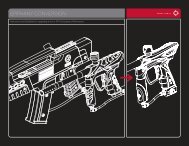
RAIL BOARDSETTINGS AND FUNCTIONSRAIL BOARDSETTINGS AND FUNCTIONSFIGURE 1BOARD SETTINGS AND CONFIGURATION MODEThere are five settings you can alter on the RAIL board withthe DIP switches inside the grip frame (see figure 1):ABSAnti Bolt Stick.Trigger Sensitivity This setting adjusts the delaybetween two trigger pulls.DwellThis is the time the solenoid isactivated for.Rate Of Fire Rate Of Fire when the eye isdeactivated.Firing Mode This is the firing mode the RAIL uses.There are two DIP switches mounted on the board of theRAIL (See figure 1). The first one is used for the ABSsetting and the second one is used to access aconfiguration mode which changes the other four settings.Anti Bolt Stick - When ABS is activated, the dwell is increased after15 seconds of non-use for the next shot fired. This helps to preventbolt-stick, but may result in higher velocity for the first shot.Configuration Mode - The following settings can only bemodified in configuration mode. To activate the configurationmode, turn your marker off and set DIP switch 2 to the ONposition. Next, turn your marker on. The LED's cycle throughall colors for one second to indicate that you have enteredthe configuration mode.To cycle through different settings, pull and release the trigger.Configuration mode has 4 settings that can be changed.NORMALMODECONFIGURATIONMODETO CHANGE A VALUE OF A SETTING1. While in the configuration mode, choose the color you wish to change by pulling the trigger.2. When the LED indicates the color you wish to change, pull and hold the trigger until the LEDstarts to flash.3. The LED will flash as many times as the previous setting was and it will then turn off. Now pullthe trigger as many times as you wish the new setting to be.4. When done, the LED will cycle through all the colors again to indicate setting was saved andturn back to green. You can now change another setting or quit the configuration mode.5. To exit configuration mode, set DIP 2 to the OFF position.ABS ON(DEFAULT)ABS OFF• The RAIL is not water resistant. Excess moisture can cause damageto electronic parts.• Keep the board and all electrical components clean of dirt, paint and moisture.• To clean the board, use canned air. If a more aggressive cleaning methodis needed, lightly scrub the components with a soft, dry brush.Heavy scrubbing will damage the board.8 9W W W . P R O T O P A I N T B A L L . C O MW W W . P R O T O P A I N T B A L L . C O M
RAIL BOARDSETTINGS AND FUNCTIONSRAIL BOARDSETTINGS AND FUNCTIONSGreen - Trigger Sensitivity Values 1 - 20 (factory default 5)Trigger sensitivity is the amount of time that the trigger has to bereleased before the next trigger pull is allowed. In some situationswith too low of a value, the RAIL can register more trigger pullsthan what was actually pulled. This can cause the RAIL to shoot fullauto, even in semi-automatic mode. To fix this, adjust the triggersensitivity setting higher.Red - Dwell Values 1 - 30 (factory default 18)Dwell is the amount of time that the solenoid will be activated.Follow these steps for the best way to set your dwell:• Remove loader and any paintballs from the RAIL marker.• With the dwell set at 10, start increasing the value until the markerbegins to fire.• When you reach the setting where the marker begins to fire, getsome paint and a loader and go to a chronograph.• Increase the dwell until you see no increase in the velocity.This is the optimal dwell setting to be used.NOTE: You cannot turn your marker off with the power buttonwhen the marker is in configuration mode. You must first set DIPswitch 2 to the OFF position.W W W . P R O T O P A I N T B A L L . C O MBlue - Rate Of Fire (ROF) Values 1 - 45 (factory default 12.5 bps)The ROF setting is used to set the maximum rate of fire of the RAIL.The values do not correspond directly to a certain Balls Per Second(BPS) value. You will need to use the table below to locate yourdesired maximum ROF setting.The factory setting is 20 (12.5 bps).1 9.80 BPS 10 10.75 BPS 19 12.34 BPS 28 13.88 BPS 37 15.87 BPS2 9.90 BPS 11 10.86 BPS 20 12.50 BPS 29 14.08 BPS 38 16.12 BPS3 10.0 BPS 12 10.98 BPS 21 12.65 BPS 30 14.28 BPS 39 16.39 BPS4 10.10 BPS 13 11.11 BPS 22 12.82 BPS 31 14.49 BPS 4016.66 BPS5 10.20 BPS 14 11.62 BPS 23 12.98 BPS 32 14.70 BPS 41 20.0 BPS6 10.30 BPS 15 11.76 BPS 24 13.15 BPS 33 14.92 BPS 42 22.22 BPS7 10.41 BPS 16 11.90 BPS 25 13.33 BPS 34 15.15 BPS 43 25.0 BPS8 10.52 BPS 17 12.04 BPS 26 13.51 BPS 35 15.38 BPS 44 28.57 BPS9 10.63 BPS 18 12.19 BPS 27 13.69 BPS 36 15.62 BPS 45 33.33 BPSIncreasing ROF too high will increase probability of ball breakage.If this occurs decrease ROF setting.Yellow - Firing Mode Values 1 - 4 (default 1)This setting changes the firing mode of the RAIL. Default issemiautomatic. In the semiautomatic mode, one trigger pullshoots out one paintball. The PSP mode and the Millenniummode follow the rules of the paintball tournament series.Value 1 - Semi-automatic ModeValue 2 - Millennium ModeValue 3 - PSP ModeValue 4 - Full Auto10 11W W W . P R O T O P A I N T B A L L . C O M
RAIL BOARDSETTINGS AND FUNCTIONSRAIL BOARDSETTINGS AND FUNCTIONSBATTERYThe 9V battery will last for about 40,000 shots. Please be aware that there are substantialdifferences in performance between different brands of batteries. Use of high quality alkaline orlithium ion batteries is recommended for maximum battery life. If you plan not to use your markerfor a long period of time (a month), it is recommended that you remove the battery from themarker. When the battery voltage starts to go too low, the marker will not fire with every triggerpull. For tournament use, it is recommended to change the battery for each tournament.CHANGING THE BATTERYThe battery is housed on the right side of the grip frame. To access the battery, remove the threescrews holding the right side grip panel down. Use a 3 ⁄32” allen key. When inserting a new batterynotice the + and - marks on the board. The positive lead of the 9V battery goes to the left and thenegative lead to the right.NOTE: If the marker will not function with the eye on, there is a good chance the battery needsto be changed.• A low battery will not be able to power both the ACE eye and the triggerswitch, causing ACE eye failure.• If the battery is low, the marker will not fire with every trigger pull.12 13W W W . P R O T O P A I N T B A L L . C O MW W W . P R O T O P A I N T B A L L . C O M
TRIGGERADJUSTMENTTRIGGERADJUSTMENTFIGURE 1231W W W . P R O T O P A I N T B A L L . C O MADJUSTING YOUR TRIGGERThe trigger’s forward travel, overtravel and spring tension are fullyadjustable so that the user canfine-tune the trigger to his or herexact liking. You do not need toremove the frame from the gunin order to adjust the trigger pull.There is one adjustment screwlocated on the right side of theUltralite frame behind the stickygrip, one adjustment screwlocated in the top of the trigger,and one adjustment screwbehind the trigger.The adjustment screw on theright side of the frame adjuststhe over travel of the trigger.The adjustment screw in the topof the trigger adjusts the forwardtravel of the trigger. The screwlocated behind the trigger isused to change the tension ofthe trigger spring.TO ADJUST TRIGGER TRAVEL (SEE FIGURE 1)• The screw in the top of the trigger (1) controls the forward travel.Screwing it in will shorten the trigger’s length of pull.Use a .50” allen key to adjust this screw.NOTE: If this screw is adjusted too far, the switch will be held down at all times and the markerwill not fire.• The screw on the right side of the frame (2) controls the over travel. By turning this screwyou can adjust how far the trigger will travel after it reaches the firing point.Use a 5⁄64” allen key to make the desired adjustment.NOTE: If this screw is adjusted too far, the trigger will not be allowed to travel far enough todepress the switch and fire the marker.TO ADJUST SPRING TENSION (SEE FIGURE 1)• The adjustment is made by pushing the allen key through a hole in the trigger (3).Use a 5⁄64” allen key to make the desired adjustment.To make the trigger pull stiffer, turn the allen key clockwise or in.To make the trigger pull lighter, turn the allen key counterclockwise or out.• Be sure the trigger is not adjusted to the point where it is too sensitiveand may cause accidental discharge of the marker.• Removing the trigger spring will cause premature wear on the microswitch,resulting in failure.• Be sure you do not pinch the wires between the frame and body whenreattaching the frame to the body.14 15W W W . P R O T O P A I N T B A L L . C O M
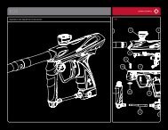
RAIL BOLTASSEMBLY AND MAINTENANCERAIL BOLTASSEMBLY AND MAINTENANCEBOLT SAILCAN BOLT MANIFOLD BACK CAPThe RAIL BOLT is the main component of the RAIL marker. In order to achieve the bestpossible performance of the RAIL it is essential that the RAIL BOLT is kept clean, well lubedand in good working order.The RAIL BOLT should be cleaned and re-lubed every 10,000 shots or after breaking paint orplaying in severe conditions.There are 4 parts in the RAIL BOLT kit that mount together as one unit. To remove the RAILBOLT from your RAIL, use a 1/4" allen key and turn the Back Cap out 1 1 ⁄2 - 2 turns. Now pull outthe complete RAIL bolt kit from the RAIL.To dis-assemble you unthread the front most part called the Can and the Manifold from eachother. Then pull out the actual moving bolt from insidethese pieces. Notice that to remove the Can you needto remove the bolt tip O-ring before the bolt is able toslide through the Can.FORWARD POSITIONHOW DOES IT WORKAir is supplied into two points on the RAIL BOLT. In theback air is routed through the Manifold and fills up thesupply chamber around the Manifold. In the front air isrouted through the solenoid into the Can. This air pushesBACK POSITIONagainst the Sail on the Bolt which keeps the bolt in the back position.16When the RAIL is fired the solenoid is actuatedand the air inside the Can is exhausted out. Thiscauses the Bolt to start moving forward with theforce created by the air inside the supplychamber. Once the bolt has moved about half wayforward, the input into the supply chamber isclosed and a patent pending Boost feature isactivated on the Back. This gives the Bolt an extrapush forward and makes sure the valve of theRAIL is opened fast and efficiently. Thesecondary benefit of this Boost feature is that onthe initial part of the Bolt movement, the Boltpushes very gently against the paintball inside thebreech reducing ball breakage.Once the Bolt reaches the forward point, the valve of the RAIL Bolt is opened and air inside thesupply chamber goes through the Bolt and fires the paintball. After this the solenoid is deactivatedand gas is supplied through the solenoid back into the Can. This causes the Bolt to returnto the back position and the supply chamber to be re-charged. Notice that when the Bolt moves tothe back position a small amount of gas used for the Boost feature is leaked out through theBack Cap.When servicing your marker:• Make sure your hopper is removed from the marker.• Make sure there are no paintballs in the breech of the marker.• Always remove the air supply and relieve all gas pressure in the markerbefore disassembly.• When using the marker in temperatures below 50° Fahrenheit it may benecessary to lube the RAIL bolt more frequently.17W W W . P R O T O P A I N T B A L L . C O M W W W . P R O T O P A I N T B A L L . C O M
RAIL BOLTASSEMBLY AND MAINTENANCERAIL BOLTASSEMBLY AND MAINTENANCEMAINTENANCEThe basic maintenance for the RAIL BOLT is toclean all surfaces of dirt, broken paint orother debris, check for any wear andtear on the O-rings and changing themif needed, and finally applying a thincoat of DYE Slick Lube on allsurfaces. Before installing the RAILBOLT back to the RAIL marker checkthat the bolt moves freely without a lot offriction.Before installing the RAIL BOLT back into the RAIL make sure all pieces are threaded togethersnugly!If the RAIL BOLT is not kept clean and well lubed, you will either start seeing erratic velocity,leaks or over long period of time, physical damage to the RAIL BOLT components.Notice that it’s normal for a small amount of gas to come out through the back cap when theRAIL is fired. This gas is used for the Patented Boost forward technology of the RAIL.For troubleshooting leaks and other bolt problems, consult the troubleshooting section at the endof this manual.009511 1 1 1 12 5649RAIL BOLT O-RING LIST1 020 BN 702 017 BN 703 016 BN 704 015 BN 705 014 BN 7076 015 BN 907 009 BN 708 007 BN 709 014x2 BN 908318 19W W W . P R O T O P A I N T B A L L . C O MW W W . P R O T O P A I N T B A L L . C O M
LOADERS AND FEED NECKAIR/NITROGENLOADERS AND FEED NECKTo achieve the maximum performanceof the RAIL you will need to use amotorized loader that force feedspaintballs into the RAIL marker,preferably the Rotor Loader. Using aslower motorized loader or a nonmotorizedloader will work,but the rate of fire and performancewill be reduced.To fit a loader onto the RAIL:1. Loosen the feed neck adjustmentthumb screw.2. Push the loader all the way into thefeed neck.3. Tighten the feed neck adjustmentscrew until loader is secure. Note thatusing too much force tightening thescrew could cause damage to yourloader.Loader should now be held in with asnug fit.There is no maintenance needed forthe feed neck besides keeping it cleanof broken paint, dirt and debris.AIR / NITROGEN TANK OPTIONS AND INSTALLATIONThe RAIL will only work with Compressed air or Nitrogenair systems such as the DYE Throttle air system. Do notuse CO 2 or any other compressed gas. Theoutput pressure from the air system has to bebetween 400 – 850psi.To install an air system, screw the tankinto the airport all the way as far as itwill go. To remove the air systemscrew out. There will be gas leakingfor a few seconds while you screwthe air system out. Notice thateven with the air systemremoved there can be gasinside the RAIL and it canstill fire a paintball. Alwaystreat the marker as beinglive and never point it toanything you don’t intendto shoot at!2021W W W . P R O T O P A I N T B A L L . C O M W W W . P R O T O P A I N T B A L L . C O M
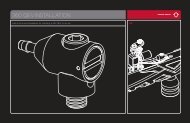
AIRPORTASSEMBLY AND MAINTENANCEON/OFF AIRPORTASSEMBLY AND MAINTENANCEAIRPORTADJUSTMENT ANDMAINTENANCEThe location of theairport adapter canbe movedapproximately 1 1 ⁄4”back or forward fromthe stock position tofit your individualpreference.The Ultralite framecomes equipped withan integrated lockingdovetail. There is alocking screw locatedon the bottom rightside of the Ultraliteframe. It can be accessed with a 1 ⁄8" allen key through a hole in the grip panel. To unlock a partattached to the dovetail of the frame, turn the locking screw counterclockwise one full turn andslide the part off the dovetail. To attach a part to the dovetail, slide the part on and turn thelocking screw clockwise until part is firmly locked in place.ON/OFF AIRPORTThe RAIL comes equipped with an On/OffAirport attached to the bottom of the frame. Toturn on the gas supply, twist the ON/OFF knobclockwise, all the way in. To turn off the gassupply, twist the ON/OFF knobcounterclockwise, all the way out. As you turnthe knob out, the residual gas between theHyper3 and the ON/OFF airport is vented.When screwing the air system into the airport,always check that the threads on the air systemand the airport are clean and not worn out. Ifyou think the threads are not in good condition,contact DYE Precision or a professional storebefore screwing in the air system.22 23W W W . P R O T O P A I N T B A L L . C O MW W W . P R O T O P A I N T B A L L . C O M
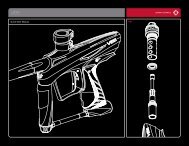
HYPER3 IN-LINE REGULATORADJUSTMENTS AND MAINTENANCEHYPER3 IN-LINE REGULATORADJUSTMENTS AND MAINTENANCEVELOCITY ADJUSTMENTThe velocity of the RAIL is adjusted by adjusting the inputpressure into the RAIL. This is controlled with the Hyper3regulator. The Hyper3 on the RAIL is factory set to 145 psi whichwill give you a velocity of about 285 FPS (Feet per Second).A 3 ⁄16” allen key will be needed for this operation. Turning theadjustment screw in (clockwise) will decrease the pressure, and out(counterclockwise) will increase the pressure. To adjust the velocity:1. Make sure you and everybody around you is wearingASTM/CE approved paintball goggles.2. Shoot the RAIL over a paintball chronograph.3. To lower the velocity turn the Hyper3 adjustment screw in.To increase the velocity turn the screw out. Only turn the screwa quarter turn at a time and shoot over the chronograph again.Notice that a few shots are needed before the change can beseen on the chronograph.MAINTENANCEFor the RAIL to function properly, it is essential that the inputpressure into the marker stays consistent at all times. The generalmaintenance needed for the Hyper3 regulator is to keep it cleanof dirt and debris at all times. A more extensive service should beperformed every 12 months by a trained Tech or if the outputpressure of the regulator doesn’t stay consistent. This can be seenas inconsistent velocity and verified with a regulator tester (soldseparately). Notice that the Hyper3 has a break in period ofabout 2000 shots before it achieves the best performance.HYPER3 REGULATOR DIS-ASSEMBLY INSTRUCTIONSTo disassemble the Hyper3 regulator you will need a 3 ⁄16” allen key and a 5 ⁄16” allen key. Place the3 ⁄16” allen key inside the top cap and the 5 ⁄16” allen key inside the bottom cap. Unscrew the bottomcap from the Hyper3 body.Next unscrew the brass seat housing from the body with a 3 ⁄16” allen key. Slide the swivel from thebody.To change the seat, pull out the old seat from the housing with a sharp object. Insert the new seatin place and push it down with a flat object. Notice that it takes about 2000 shots for the seat toperfectly sit into the seat housing. This is called the break in period for the regulator.Remember to apply lube to the 010 and 013’s in the regulator before re-assembly.Further disassembly to service the top section of the Hyper3 should be performed bya trained Tech.010 BN 70 007 UR 90 013 BN 70011 BN 70BOTTOM CAP SWIVEL SEAT HOUSING REGULATOR SEAT BODYTOP CAP24 25W W W . P R O T O P A I N T B A L L . C O MW W W . P R O T O P A I N T B A L L . C O M
ANTI CHOP EYES/ BALL DETENTSMAINTENANCE AND CHANGINGANTI CHOP EYES/ BALL DETENTSMAINTENANCE AND CHANGINGANTI CHOP EYESThe Anti Chop Eye (ACE)system will prevent the RAILfrom chopping paint by notallowing the marker to fire untila ball is fully seated in front ofthe bolt. The eyes use a beamacross the breech. On one sidethere is a transmitter, and on theopposite side a receiver. In orderfor the marker to fire with theeyes turned on, the signalbetween the two eyes must bebroken. After every shot, beforethe next ball drops in thebreech, the eye transmitter andreceiver must see each other. Ifthe eyes are dirty and cannotsee each other between shots,the LED on the board will start blinking green. This means that the eyes are dirty. This is anextremely reliable system as long as the eyes are kept clean. The most common reason for dirtyeyes is broken paint. If the eyes become dirty, the marker will default to a reduced rate of fire toprevent chopping. If this happens during game play, you can bypass this by turning the eyes off.Clean the eyes as soon as possible.NOTE: IF THE BATTERY IS LOW, THE MARKER MAY ACT AS IF THE EYES ARE DIRTY OR NOTFIRE AT ALL. IN THIS CASE, REPLACE THE BATTERY.W W W . P R O T O P A I N T B A L L . C O MCLEANING THE ANTI CHOP EYESQuite often, just cleaning the breech out with a swab will clean the eyes well enough for them toread one another. For a thorough cleaning, the best method is to use air. Using an air hose orcanned air (typically used for dusting keyboards) works best.Blow the eyes clean from inside the breech. If you feel the eyes still need a more detailed cleaning,remove the eye cover to gain full access to the eyes.To remove the eye cover, you will need a 1/16” allen key, take caution not to loose the detentspring when removing the eyeplate.NOTE: Regular eye cleaning is recommended even if no paint is broken. Clean the eyes every twomonths or 10,000 shots to eliminate any built up dirt. Excess grease from the front bolt O-ringcan build up in front of the eyes. Remember to check for this after greasing the bolt and cyclingthe marker a few times.CHANGING BALL DETENTSThe ball detent system is also located under the eye covers. The ball detent system needs little orno maintenance. There is a spring behind each detent, which holds the detent forward. This springpressure should be easily overcome with very little force, such as a paintball moving past. If youare experiencing double feeding or chopping, check the condition of your ball detents with yourfinger to make sure they are not stuck in the up or down position and that they move in and outof the breech freely. If excessive broken paint or dirt has jammed your ball detents, remove theeye plates (being careful not to lose the detent springs) and pull the detents out for a thoroughcleaning. Reinstall the detents, springs and eye covers after you have sufficiently cleaned thedetents and breech.NOTE: TAKE CARE WHEN REPLACING THE EYE COVER. OVER-TIGHTENING THE RETAININGSCREW COULD RESULT IN STRIPPING THE THREADS.26 27W W W . P R O T O P A I N T B A L L . C O M
TROUBLE SHOOTING GUIDEAIR LEAKSAIR LEAKING FROM THE AIRPORT• Check the o-ring on the air system. If neededchange the O-ring and try again. The O-ringnormally used is #15 but some manufacturersmight use a different size. Consult the manualof the air system you are using.• Check that the hose connector is tight.Remove the hose from the connector bypushing the floating ring towards theconnector and pull out hose.Use a 7/16” allen key to tighten. If neededremove and apply thread sealant to the threadand re-tighten. If unsure consult expert advice.• Check that the end of the hose is cut straightand is not worn out. If needed cut a small pieceoff the hose with a razor blade and re-inserthose into the fitting.Make sure hose goes all the way to the end.AIR LEAKING FROM THE HYPER3 REGULATOR• First locate the position of the leak.• For disassembly instructions consult thetechnical section under Hyper3 regulator.• If the leak is coming from the bottom of theregulator you will need to disassemble theregulator and change the #010 O-ring andthe seat on the brass seat retainer mountedinside the Hyper3 regulator.• If the leak is coming from the swivel piecewhere the hose connector mounts, you willneed to change the two #013 O-rings underthe swivel piece or tighten the hose connector.• If the leak comes from the small hole in themiddle of the regulator there are two possibleO-rings. Change the #015 O-ring on thepiston and the #007 urethane O-ring insidethe body of the regulator.• If the leak is from the top of the regulatorchange the #012 O-ring on the outsideof the cap.AIR LEAKING FROM THE ASA• First make sure that the ASA is tightened wellinto the body of the RAIL by removing theHyper3 regulator and tightening the ASAwith a 3/16” allen key.• Next change the #012 O-ring on the top cap ofthe Hyper3 and apply a small amount of lubeto the O-ring.• Finally, if above steps don’t help, remove theASA with a 3/16” allen key and change the#012 O-ring mounted on the top of the ASA.Apply a small amount of lube and tightenback together.AIR LEAKING BETWEEN BODY AND FRAME• A leak between the body and the frame can becaused by a couple of things.• First pull out the Bolt kit and change the #015sail O-ring and the three #020 O-rings on theoutside of the Can.W W W . P R O T O P A I N T B A L L . C O M• If above doesn’t help, remove the frame fromthe RAIL and remove the solenoid byunscrewing the two screws mounting it down.Apply some lube to the seat underneath thesolenoid and re-assemble making sure that thesolenoid is well tightened into the body andthat the eye wire is not pinched underneaththe solenoid.• Last possibility is that one of the gas passagesis leaking. Gas up the RAIL without the frameattached and try to locate the exact point ofleakage. If the leak is coming from one of theblocked holes remove the screw, apply somethread sealant and re-attach screw to the body.AIR LEAKING FROM BACK OF THE RAIL• Check that the bolt kit is tightened all the wayinto the RAIL. If the bolt kit is loose, it willstart to leak.• If above does not solve the leak, remove thebolt kit and change the #020 O-ring on theback part of the bolt. Also change the two#009 O-rings located in the stem of the bolt.Lube well and re-insert the bolt kit into theRAIL. Check bolt kit break down picture onpage 19 for O-ring locations• Last, check that the gas passage blockingscrew located on the right side of the RAIL isnot leaking. If the leak is coming from this hole,remove screw and apply thread sealant to it.Make sure to tighten the screw well and waitfor sealant to dry before re-gassing marker.TROUBLE SHOOTING GUIDEW W W . P R O T O P A I N T B A L L . C O MAIR LEAKING FROM FRONT OF THE RAIL• Remove the Bolt kit from the marker andchange the #017 O-ring located insideof the Can and the #014 O-ring located insidethe Manifold. Lube well and re-assemble.• If above doesn’t help, try changing the #020O-rings located outside of the Can.Lube well before re-inserting bolt kit.PROBLEMS WITH ELECTRONICSRAIL WON’T TURN ON• Make sure battery is new and well charged.• Check that battery is connected to the 9V clipinside the RAIL .• Make sure there is no dirt or debris blockingthe button from being pressed.RAIL WILL TURN ON / OFF BY ITSELF OR THEEYES WILL TURN ON / OFF BY THEM SELVES• Both of these problems are caused becausethe button(s) are pressed all the time.• Remove board from the frame by removing thegrip panel on the left hand side, disconnectingthe cables and pulling the board out. Carefullyremove the two buttons and clean them well.• Re-assemble and test. If problems persist,contact authorized service center for boardreplacement.28 29
TROUBLE SHOOTING GUIDEEYES WILL NOT WORK, LED KEEPSBLINKING GREEN• First change the battery. The eyes are normallythe first thing to stop working when a batteryis dying.• Next try to clean the eyes. You can either usecanned air and blow out the eye holes throughthe feed neck hole. Or remove the eye plateswith a 1/16” allen key, pull out the eyes from themounting holes carefully and clean them withq-tips. To test if the eyes work make sure thereis nothing inside the breech and that the bolt isin the back position. Turn on the RAIL, thelight should be red after the boot up sequence.If it is, the eyes are working.• Check that the eye wire is connected to theboard so that metal clips are facing down.• If nothing above helps contact a store or DYEPrecision for eye replacement.SOLENOID WILL NOT ACTIVATE / TRIGGERNOT WORKING• Check that the trigger adjustment is not set sothat the micro switch cannot activate.You should hear a small click when pullingthe trigger.• If the RAIL fires once when turned on but notafter that your trigger is set so that the microswitch is always activated. Re-adjust the trigger.• If the trigger is correctly adjusted but theRAIL still won’t fire, check that the microswitch cable is well inserted into the board andto the correct connector (the micro switchconnector is marked with the text “SWI” onthe board).• Change the battery if not positive about it’scharge.• Check that the solenoid cable is attached tothe board and to the right connector (solenoidshould be attached to the connector that ismarked with the text “SOL”).TRIGGER BOUNCE / RAIL SHOOTING MORETHAN ONE BALL PER PULL IN SEMI AUTOMATICMODE• Raise the trigger sensitivity level in theconfiguration mode.• Check that the trigger is not adjusted tooshort.• Make sure there is a trigger spring insidethe frame.ERRATIC VELOCITY/RAIL WON’T FIRERAIL FIRES BUT BALLS ARE DROPPING OFFOR NOT EVEN COMING OUT OF THE BARREL• Make sure the battery is good.• Raise the dwell to factory level (18).• Make sure bolt is well lubed and moves well.If there is too much friction in the Bolt, it willcause the RAIL to shoot down.• Make sure air system is screwed in all the way.W W W . P R O T O P A I N T B A L L . C O MFIRST SHOT IS TOO HIGH• Change the Seat inside the Hyper3 regulator.For disassembly instructions consult thetechnical section.• Check that the #013 O-ring on the outside ofthe Manifold is in place and in good condition.• Try turning off the ABS feature by turning DIP#1 to the off position.VELOCITY IS NOT CONSISTENT• Make sure the paintballs you are using fit thebarrel good and are consistent in size.The stock barrel with the RAIL is .690 size.You should be able to blow the paintballthrough the barrel but they should not rollthrough the barrel on their own.• Remove the bolt kit and re-lube it. Change anyO-rings causing a lot of friction. Make sure#014 O-ring in bolt tip is in place and ingood condition.• Raise the dwell.• Change the battery.• Check that the Hyper3 regulator is workinggood and that the pressure is consistent.A separate regulator testing tool is availablefor this. If needed, disassemble and changeworn out O-rings in the Hyper3 regulator.TROUBLE SHOOTING GUIDEW W W . P R O T O P A I N T B A L L . C O MOTHER CATEGORIESDOUBLE FEEDING• If you get two balls firing at once changethe ball detents by removing the eye plates,taking out the old ball detents and insertingnew ones.BREAKING PAINT• Make sure you use high quality paintballs andthat they are stored according to themanufacturers instructions.• Check that #14 O-ring on bolt tip is in placeand in good condition.• Make sure your loader is working good andthat the rate of fire is not set higher than themaximum feed rate of the loader.• Check that the barrel you are using is not tootight for the paintballs you are using.• Check the condition of the ball detents.30 31
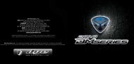
12EXPLODED VIEWRAIL WARRANTY INFORMATIONWARRANTY AND LEGAL INFORMATION541416639171041485713111512PARTS LIST1 Clamping Feed Collar2 Feed Neck Knob3 Feed Neck4 Ball Detent5 Eye Cover6 Hyper37 “ACE” Eye8 Solenoid9 Front Frame Screw10 Ultralite Frame11 Rear Frame Screw12 RAIL Bolt13 RAIL Body14 Eye Cover Screw15 Airport16 ASA17 Solenoid screwsWARRANTYDYE Precision, Inc. warrants for one year to the initial retail purchaser, from the initial date ofpurchase, that the paintball marker and regulator are free from defects in materials andworkmanship, subject to the requirements, disclaimers and limitations of this warranty. Disposableparts, normal maintenance and standard wear and tear parts such as batteries, O-rings and sealsare not covered under warranty. The solenoid and electronic components on the marker arecovered under warranty for six months. This warranty does not cover scratches, nicks, improperdisassembly, improper re-assembly, misuse, neglect or improper storage. Modification to theproduct will void the warranty. The only authorized lubricant for the marker is Slick Lube. Use ofany other lubricant will void your warranty. This warranty is limited to repair or replacement ofdefective parts with the customer to pay shipping costs. Warranty card and proof of purchase mustbe submitted to DYE Precision for warranty to be in effect. This warranty is not transferable. Thiswarranty does not cover performance. <strong>Paintball</strong> markers are non-refundable.TECHNICAL SUPPORTOur Technical Support Departments are open Monday through Friday.DYE Precision, Inc. can be reached at 858-536-5183 ext.277 from 9am to 5pm PST.DYE Europe can be reached at +44 (0) 20-8649-6330 from 9am to 5pm GMT.DYE Asia can be reached at 886 (0) 4-2407-9135 from 9am to 5pm GMT +8 hours.Additional support and international contacts are available through our web site, www.dyepaintball.com.DISCLAIMERThe specifications & photographs in this material are for information and general guidancepurposes only. Our products are continually updated and changes may be made to specification,design or appearance from time to time. These are subject to change without notice. Contents ofbox may therefore vary from owner’s manual. For details of changes in design, specification orappearance consult your local distributor or dealer. The FUSE BOLT, RAIL, Hyper3 and SlickLube are registered trademarks. Design rights, copyrights and all other rights reserved.All patterns, drawings, photographs, instructions or manuals remain the intellectual propertyof the manufacturer.DYE Precision, Inc. U.S. Patent # 5,613,483. OTHER U.S. AND INT’L PATENTS PENDING. Covered byone or more of the following U.S. Patents, 5,613,483; 5,881,707; 5,967,133; 6,035,843 and 6,474,326.All rights will be strictly enforced.DYE Precision, Inc.10637 Scripps Summit Ct.San Diego, CA. 92131DYE Europe<strong>Dye</strong> House,7-8 Commerce WayCroydon, SurreyUnited Kingdom CR0 4XAW W W . P R O T O P A I N T B A L L . C O MDYE AsiaNo. 253, Guojhong Rd.Dali City, Taichung County 412Taiwan (R.O.C.)32 33