Operation and adjustment instructions - P8ntbox
Operation and adjustment instructions - P8ntbox
Operation and adjustment instructions - P8ntbox

You also want an ePaper? Increase the reach of your titles
YUMPU automatically turns print PDFs into web optimized ePapers that Google loves.
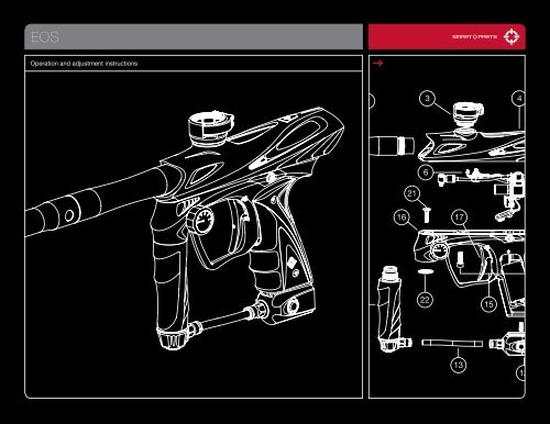
EOS<strong>Operation</strong> <strong>and</strong> <strong>adjustment</strong> <strong>instructions</strong>2 34216161722151312
QUICK STARTPLEASE READ CAREFULLY01 02 03BATTERY BARREL BLOCKER FILL TANKThe EOS is powered by ast<strong>and</strong>ard 9-volt battery. Toverify that a battery is installed,or to install a new one, usea 5/64-inch Allen wrench toremove the two screws fromthe left side of the rubber grip<strong>and</strong> lift the panel open. Thebattery should be attached tothe battery clip, <strong>and</strong> placed inthe grip frame with the batterywires tucked in above it. When changing batteries, pull the batteryclip from the battery directly, do not pull on the wires. With thebattery secure, close the grip <strong>and</strong> reinstall the screws.Screw the included barrel into the EOS.Slide the included barrel blocker overthe barrel <strong>and</strong> secure its cord as farback on the EOS body as possible,cinching it tight. The barrel blocker is acritical piece of paintball safety equipment– nearly as important as paintballgoggles. The barrel blocker must befully seated on the marker’s muzzle <strong>and</strong>secured in place with its strap any timethe marker is stored or h<strong>and</strong>led in anarea where people or property are notproperly protected by paintball gogglesof paintball field netting.Have yourcompressed air(HPA) or CO2 tankfilled by a personwho is properlytrained to do so.If using an HPAsystem with anon/off valve, suchas the Max-Flo orMax-Flo Micro,make sure it is inthe OFF position.04 05 06LOADER TURN ON AIR TURN ON EOSThe EOS is a high-performancetournament grade marker. Thebreak-beam Vision system willallow it to use a low-end hopperwithout chopping paintballs. Ahigh-performance, preferablyforce-feeding loader must beused to achieve maximum ratesof fire. Open the marker’s Q-Lockfeedneck by pulling the lockinglever away from the feedneck,then insert the loader <strong>and</strong> secureit in place by folding the leverback to its locked position.Gently gas up the markerby slowly turning on the airsystem or ASA’s on/off valve,or slowly screwing the CO2 orcompressed air system intothe ASA.A gentle rise in pressure isimportant, as a sudden blastmay reduce the service life ofthe EOS’s internals.POWER BUTTONTurn the marker on by pressing the powerbutton, <strong>and</strong> holding it in for a full second.When the EOS turns on, the power buttonwill glow red. The EOS is turned off bypressing <strong>and</strong> holding the power button forone second. To conserve battery power, theEOS will turn itself off if it is not fired for morethan 15 minutes. Pressing the power buttonmomentarily while the EOS is on, will deactivatethe Vision anti-chop system, which isindicated by the power button blinking.Although the power button serves as the EOS’s safety switch to preventaccidental firing, it should never be relied upon in place of a barrel blocker <strong>and</strong>proper paintball eye protection.07ADJUST VELOCITYFill the hopper with paintballs <strong>and</strong> turn it on. While wearing ASTM compliant paintball goggles, in an area where all byst<strong>and</strong>ers are protected, remove the barrel blocker <strong>and</strong> fireover a chronograph to measure the velocity. Using a 5/32-inch allen wrench on the adjuster in the bottom of the vertical regulator, turn clockwise to increase velocity/pressure, <strong>and</strong>counter-clockwise to decrease. Take three or four shots after every <strong>adjustment</strong> to allow the gas pressure inside the EOS to stabilize. Adjust until the marker is firing consistentlywithin the limits for the field where you are playing (for safety reasons, never adjust the EOS to fire at greater than 300 feet per second.) As you adjust, check the EOS’ pressuregauge to be certain you stay below the EOS’ operating limit of 280 psi. Depending on what modes of fire are allowed at the field where you are playing (semi-automatic, rebound,etc.) you may need to adjust the EOS’ firing mode. See the Electronic Adjustment section for more information. Shoot out the competition, hang the flag <strong>and</strong> win the game.Increasing Velocity.00800.922.2147 www.smartparts.com
TABLE OF CONTENTSQuick StartGetting FamiliarBarrel Blocker/HopperGasesGas System MountingPaint/VelocityVision/DegassingElectronic AdjustmentDwellROF Delay/Fire ModesTrigger [ DISASSEMBLY/REASSEMBLY ]EOS PartsDisassemblyEOS Volume InsertsAdvanced DissassemblyReassemblySolenoidBall DetentsTroubleshootingWarranty/Tech SupportCPS Table00020304-0506070809101112131415-1617-1819202122-252526– THE EOS IS NOT A TOY.– MISUSE OF THE EOS MAY RESULT IN SERIOUS INJURYOR DEATH.– EYE PROTECTION SPECIFICALLY DESIGNED FORPAINTBALL USE MUST BE IN COMPLIANCE WITH ASTMSPECIFICATION F1776 AND MUST BE USED BY THE USERAND ANYONE WITHIN RANGE OF THE EOS.– WEAR EYE PROTECTON DURING DISASSEMBLYOR MAINTENANCE.– SMART PARTS RECOMMENDS THAT THE EOS ONLY BESOLD TO PERSONS 18 AND OLDER.– THOROUGHLY READ THE EOS MANUAL BEFOREOPERATING.– TREAT EVERY PAINTBALL MARKER AS IF IT WERE LOADED.– NEVER LOOK DOWN THE BARREL OF A PAINTBALL MARKER.– KEEP YOUR FINGER OFF THE TRIGGER UNTIL READYTO SHOOT.– NEVER POINT THE EOS AT ANYTHING YOU DON’T WISHTO SHOOT.– KEEP THE EOS ON SAFE (POWER OFF) UNTIL READYTO SHOOT.– KEEP THE BARREL BLOCKING DEVICE ON THE EOS’SMUZZLE WHEN NOT SHOOTING.– ALWAYS REMOVE PAINTBALLS AND DEGAS THE EOSBEFORE DISASSEMBLY.– STORE AND TRANSPORT THE EOS UNLOADED ANDDEGASSED IN A SECURE PLACE.– FOLLOW ALL MANUFACTURER’S WARNINGS ANDINSTRUCTIONS FOR PROPELLANT SOURCE HANDLING,STORAGE, AND FILLING.– DO NOT SHOOT FRAGILE OBJECTS SUCH AS WINDOWS.– ALWAYS MEASURE THE VELOCITY OF PAINTBALLS FIRED BYTHE EOS BEFORE USE, AND NEVER ADJUST TOFIRE ABOVE 300FPS (91.44 M/S.)While every effort has been made to ensure that the information contained in this guide is accurate <strong>and</strong> complete, no liability can be accepted forerrors or omissions. Smart Parts, Inc. reserves the right to change the specifications of the EOS at any time without prior notice. The latest version ofthis manual may be downloaded free of charge at www.SmartParts.com.800.922.2147 www.smartparts.com01
GETTING FAMILIARPLEASE READ CAREFULLYSTATISTICSREQUIRED ALLEN WRENCHESLENGTH/HEIGHT/WEIGHT:OPERATING PRESSURE:PAINTBALLS:POWER SOURCE:PROPELLANT:RATE OF FIRE:OPERATION:MODES OF FIRE:ANTI CHOP SYSTEM:BARREL THREAD:GAS EFFICIENCY:LUBRICANT:20 Inches (with stock 14” barrel) / 8.25 Inches (with on/off ASA) / 2lbs, 3oz (marker only)Approx. 260 psi, 280 psi max.68 caliber –Compliant to ASTM F1979 Specification9-volt alkaline batteryCO 2or Nitrogen/Compressed air17 bps maximum – 20 bps max with optional Blackheart boardLow pressure electropneumaticFull Auto, 3-shot burst, Semi automatic <strong>and</strong> ReboundBreak Beam VisionSmart Parts1200 shots (68ci, 4500psi tank), 800 shots (20oz. ANTI-SIPHON tank) – Efficiency will vary with paint,barrel <strong>and</strong> setting combinations.For proper <strong>and</strong> consistent operation, the EOS should only be lubricated with SL33K lubricating grease..050" 5/64" 3/32" 1/8" 5/32" 5/16"MAINTENANCEThe EOS has been designed with simplicity in mind so that you can concentrate on your game instead ofyour marker. It has a minimal number of moving parts <strong>and</strong> seals so that you can maintain the marker withlittle effort. This DOES NOT mean that you should neglect your marker. If you take care of it off the field,your EOS will take care of you on the field. For best performance, clean <strong>and</strong> grease your EOS frequently.Many players clean their marker after every use. While this may seem a bit extreme, being vigilant in theupkeep of your marker will extend its useful life considerably. Playing in the rain will not damage your EOS,but you should NEVER immerse it in water. If your marker should become waterlogged, remove the barrel,body cover <strong>and</strong> rubber grips <strong>and</strong> allow them to dry out, then follow the disassembly <strong>instructions</strong> forfull cleaning. Clean out mud <strong>and</strong> paint with a damp cloth <strong>and</strong> alcohol. Grease the EOS ONLY with SL33Kpneumatic grease. For best performance, use high quality paintballs.02800.922.2147 www.smartparts.com
BARREL BLOCKER/HOPPERPLEASE READ CAREFULLYBARREL BLOCKERThe Barrel Blocking Device is a critical piece of paintball safety equipment - nearly as important aspaintball goggles. The Barrel Blocker serves to protect against accidental discharge of a paintball bycatching it before it can cause harm. A Barrel Blocker is included with the EOS, <strong>and</strong> must be usedevery time the marker is h<strong>and</strong>led in an area where people or property are not properly protected bypaintball goggles or paintball field netting. To use the Barrel Blocker simply slip it over the end of thebarrel <strong>and</strong> stretch its cord back over the back of the marker or the rearmost part over which it canbe securely looped. Use the strap’s adjuster to cinch the strap tight, so that the Barrel Blocker canprovide protection against accidental discharge of a paintball.FIG. 1BARREL BLOCKER IN USEThe Barrel Blocker should only be removed when the marker is on a “live” paintball field <strong>and</strong> allpersons involved are wearing proper paintball protection.HOPPERThe EOS is a high performance tournament grade paintball marker. The break-beam Vision systemmeans that you won’t need to worry about chopping paint because your trigger finger is faster thanyour hopper. However, if you want to realize the marker’s maximum firepower potential, you will needto use a high performance loader. High performance loaders, especially those which provide forcefeeding,will yield the best results with the EOS.Open the marker’s Q-Lock feedneck by pulling the locking lever away from the feedneck, then insertthe loader <strong>and</strong> secure it in place by folding the lever back to its locked position. The adjuster nut canbe used when the lever is unlocked, to compensate for a larger or smaller hopper neck.FIG. 2USE HIGH PERFORMANCE LOADER800.922.2147 www.smartparts.com03
GASESNever put oil in a compressed air regulator or tank—onlyapply manufacturer specified lubricants.TThe EOS is a low-pressure paintgun. It is normally set to approximately 260 psi, <strong>and</strong> will operateproperly anywhere between 250 <strong>and</strong> 280 psi. It may utilize either compressed air or CO2 as a powersource. This pressure level allows the EOS to operate with a small valve chamber which recharges fast,delivering velocity consistency at 15 balls per second <strong>and</strong> higher rates of fire. Proper set up of your gassystem will help you obtain the best possible performance.High Pressure Air systems (HPA) are the most common power source used with the EOS, as they areunaffected by temperature fluctuations <strong>and</strong> do not have the potential for liquid problems. HPA systemsconsist of a tank <strong>and</strong> a regulator, <strong>and</strong> are typically rated to store air or nitrogen (while nitrogen is almostnever used in paintball, many players call compressed air “nitro” as air is made of more than 70%nitrogen) at pressures of 3,000 or 4,500 psi.There are two main types of HPA systems, those on which the output pressure is adjustable, <strong>and</strong> thosefor which their regulator is pre-set to a fixed output pressure. HPA systems designed to screw into anASA are usually pre-set to deliver either 400 psi (low pressure output) or 800 psi (high pressure output.)FIG. 3FIG. 4HPA TANK BEING FILLEDCOMPRESSED AIRNever use oil or any petroleum based cleaner or lubricant in a compressed air regulator or tank.Exposure to pressurized air increases oil’s flammability <strong>and</strong> can cause a serious safety hazard. Only usemanufacturer recommended lubricants with compressed air systems, <strong>and</strong> follow the manufacturer’smaintenance <strong>and</strong> operation <strong>instructions</strong> explicitly.If you are using your EOS with an adjustable output compressed air system, it should be adjusted todeliver about 650 psi to the marker’s vertical regulator. The EOS’ regulator can accommodate a widerange of input pressures, so exact <strong>adjustment</strong> of the air system is not critical, <strong>and</strong> either low output, orhigh output pre-set HPA systems may be used as well.While CO2 can also be used, it is less popular, since its pressure fluctuates with temperature <strong>and</strong> use. Forreliable operation, liquid CO2 must not be delivered to the marker. Although the relief valve in the Max-Flo R regulator will protect the internal components of the EOS from damage caused by liquid relatedpressure spikes, liquid CO2 will still hamper consistent operation. Because liquid CO2 is heavier than CO2gas, it is easily blocked through the use of gravity.FIG. 5CO2 WITH ANTI-SIPHON [CUTAWAY VIEW]The relief valve in the Max-Flow R regulator protects the EOS from liquid CO2 related overpressure. Do notuse CO2 with any other regulator, or internal damage may result.04800.922.2147 www.smartparts.com
GASESPLEASE READ CAREFULLYTwo easy ways to properly use CO2 with the EOS are an anti-siphon tank or a remote line.Anti-siphon tanks have a J shaped tube professionally installed inside. When the tank is screwed into abottom line ASA, such as the one that is st<strong>and</strong>ard on the EOS, the tube delivers gas only. The anti-siphontube works like a diver’s snorkel, repositioning the gas intake from the valve, to the top side of thetank. When an anti-siphon tube is installed in a tank, the airsmith will usually mark the valve, to indicatethe position of the tube. When the tank is screwed into a marker, this mark must be oriented to the top.A remote hose allows a st<strong>and</strong>ard (non-siphoned) CO2 tank to be carried in a player’s pack. Not only doesthis reduce the total weight of the marker, but it also allows the tank to be placed vertically, so that itsvalve is at the top while gravity holds the liquid CO2 at the bottom. It is important to note that lying downon the field or crawling while using a remote can cause liquid CO2 to be fed to the paintgun as the tank isturned on its side.Whether using compressed air or CO2 it is important that the marker is not exposed to sudden “pops”of pressure. If using a st<strong>and</strong>ard ASA with a screw in HPA system or CO2 tank, screw the tank in slowly,so that the valve opens slowly <strong>and</strong> the pressure rises gently. If using an ASA with a built in on/off valve,screw in the tank fully, then open the valve slowly. If using an HPA system or CO2 tank with its own on/offvalve, open that valve slowly. Be gentle to the internals of your marker <strong>and</strong> they will reward you with along service life.IMPORTANTCO2 can also be used with remote hosewith-out Anti-Siphon. [Not Shown]800.922.2147 www.smartparts.com05
GAS SYSTEM MOUNTINGPLEASE READ CAREFULLYFIG. 6BOTTOM OF GRIP FRAMEThe EOS offers multiple gas system mounting options. While it has a pair of 10-32 screw holes, it alsofeatures an integrated air system rail which can be used for low profile air system attachment.The EOS is preconfigured with a dovetail mount on/off ASA mounted on the rail. To remove this ASA,degas <strong>and</strong> unload the EOS. Take off the EOS’ flexible wraparound grips, then unplug <strong>and</strong> remove the9-volt battery from the grip frame. Using a 3/32 allen wrench through the hole inside the grip frame,loosen the set screw in the forward grip frame screw hole. The ASA will now be free to slide off the rail.To use 10-32 screw mounted accessories instead of rail mounted accessories, completely remove theset screw from the grip frame. If reinstalling it, be sure to thread it in from the bottom of the frame, hexside up.FIG. 7INSTALLING SET SCREWFIG. 8TIGHTENING SET SCREW06800.922.2147 www.smartparts.com
PAINT/VELOCITYPLEASE READ CAREFULLYPAINTEven the best quality paintballs will vary in size from one batch to the next <strong>and</strong> as weather conditionschange. While your marker will work well even with a poor paint to barrel fit, optimal performance willbe achieved with a proper fit. Paintgun barrels are available in a variety of bore sizes to allow the user toselect the best possible fit, <strong>and</strong> barrel kits like The Freak allow for easy <strong>adjustment</strong> to paint of differentdiameters.The ideal fit between the paintball <strong>and</strong> the barrel is when the ball is inserted in the bore (the end thatscrews into the marker) <strong>and</strong> does not slip or roll through to the muzzle (the business end) on its own. Theball should sit in place, even when the barrel is pointed straight down. If the paintball can roll out on itsown, the fit is too loose. The ball should be able to be expelled from the barrel by blowing it out like ablowgun, using a minimal amount of breath. If the ball is difficult to blow through, the fit is too tight, whichcan lead to ball breakage.FIG. 9INCREASING VELOCITYVELOCITYThe velocity, or speed at which the EOS fires a paintball, must be measured <strong>and</strong> adjusted to below thepaintball field’s velocity limit immediately before each day of play. This is required for player safety. If CO2is used, velocity should be checked <strong>and</strong> adjusted multiple times during the day. While wearing properpaintball speficic goggles <strong>and</strong> protective equipment, <strong>and</strong> in an area in which all persons <strong>and</strong> property areproperly protected, fire three or four shots over a chronograph <strong>and</strong> if necessary change the velocity byadjusting the vertical regulator with a 5/32-inch allen wrench. Turn clockwise to increase velocity/pressure,<strong>and</strong> counter-clockwise to decrease. Take three or four shots after every <strong>adjustment</strong> to allow the gaspressure inside the marker to stabilize. Adjust until the marker is firing consistently within the limits for thefield where you are playing. For safety reasons, never adjust the marker to fire at greater than 300 feet persecond. As you adjust, check the pressure gauge to be certain you stay within the EOS’ operating pressurerange of 250 to 280 psi. If the desired velocity can not be set within that pressure range, <strong>adjustment</strong>of the fire chamber volume may be necessary. See the EOS volume control inserts section of this manualfor more information.800.922.2147 www.smartparts.com07
VISION/DEGASSINGPLEASE READ CAREFULLYVISION INSTRUCTIONSWhen the EOS is turned on it will be in Vision mode. The internal infra-red eye will be used to detectwhether or not a paintball is in the breech. This feature practically eliminates the possibility of a choppedpaintball. Vision mode is indicated by a rapid blinking of the light in the power button when there is apaintball in the breech, or a slow blinking when it is empty. Vision mode can be de-activated by pressingthe power button quickly while the marker is on. Vision mode off is indicated by a double-tap blinkingpattern on the power button light. Vision mode may be turned back on by once again pressing thepower button briefly.FIG. 10LEDsPROGRAMMING BUTTON/LEDDEGASSINGAt the end of each day’s use <strong>and</strong> before performing maintenance work on your marker, it will need to bedegassed, <strong>and</strong> all paintballs must be removed. In an area where it is safe to shoot (such as the chronographarea at a paintball field) <strong>and</strong> while wearing paintball goggles, remove the hopper from the feedneck.By turning the marker upside down, you can empty any extra paintballs from the feedneck intoyour h<strong>and</strong>. Turn the marker on, then deactivate Vision mode by pressing the power button momentarily.Dry-fire 2 or 3 shots in a safe direction to ensure that no paintballs remain in the marker. Turn off thecompressed air system or on/off ASA, or unscrew the compressed air system or CO2 tank far enough toclose its pin valve.Continue to dry fire the marker in a safe direction until all of the gas pressure inside has been released.At this point the only sound you should hear when you pull the trigger is the click of the solenoid valve.Turn off the EOS by pressing <strong>and</strong> holding the power button for two or more seconds.If using a CO2 tank or screw in HPA system, unscrew it the rest of the way.If the marker is to be stored for an extended period of time, remove the 9-volt battery from the gripframe.PROGRAMINGBUTTONEven with no CO2 tank or compressed airsystem attached, the marker may still haveenough gas pressure stored in the regulator<strong>and</strong> fire chamber to fire 2 or more shots.You must degas your EOS before storage ormaintenance.08800.922.2147 www.smartparts.com
ELECTRONIC ADJUSTMENTIMPORTANTSETTING LIGHT INDICATION MODE FUNCTIONONETWOTHREEFOURFIVESIXDwell Up [solid yellow]Dwell Down [solid red]ROF Delay Up [shoot slower/blink yellow]ROF Delay Down [shoot faster/blink red]Firing Modes Up [double blink yellow]Firing Modes Down [double blink red]FIG. 11TURNING ON EOSPOWERBUTTONELECTRONIC ADJUSTMENTDwell, Rate of Fire Delay <strong>and</strong> Mode <strong>adjustment</strong>s are made using the marker’s programming button <strong>and</strong>power button. Removing the two grip screws on the left side of the EOS grip frame <strong>and</strong> folding the gripback provides access to the programming button. The button is small, gray <strong>and</strong> rectangular in shape.It is mounted on the circuit board facing the left edge for easy access. A notch in the board helps toidentify the button <strong>and</strong> make it easier to press.Yellow <strong>and</strong> red light emitting diodes (LEDs) are located on the circuit board just above the programmingbutton. The patterns which flash on these buttons indicate the function the power button will performwhen pressed.To enter the programming modes, make sure the EOS is completely degassed <strong>and</strong> unloaded, with abarrel blocker properly in place. Turn the marker on <strong>and</strong> note that the programming LEDs are not lit orflashing. This indicates that the EOS is in operational mode rather than a programming mode. To selectone of the programming modes, press the programming button <strong>and</strong> note the sequence of blinkingLEDs to determine which mode you have selected. The yellow LED indicates that you have selected toincrease a setting, <strong>and</strong> the red LED indicates that you have chosen to decrease a setting. The LED willbe lit solidly for <strong>adjustment</strong> of the dwell, single blink for <strong>adjustment</strong> of the ROFDelay <strong>and</strong> double blinkfor <strong>adjustment</strong> of the firing mode.To change a particular setting, choose the appropriate mode, then press the power button. Both LEDswill blink to acknowledge that the <strong>adjustment</strong> has been made. When only the red LED blinks afterpressing the power button, this indicates that you have reached the lower limit of <strong>adjustment</strong>. Similarlyonly the yellow LED will blink to indicate that the upper <strong>adjustment</strong> limit has been reached. Pull the triggerto exit the programming mode <strong>and</strong> save your new settings.PROGRAMMING EXAMPLETo set a dwell value of 18ms, first pressthe programming button as many times asneeded to light the red programming LEDsolidly. Then press <strong>and</strong> hold the power buttonuntil the red LED blinks alone, indicatingthat the bottom of the <strong>adjustment</strong> range(8ms) has been reached. Press the programmingbutton again to cycle through theprogramming modes until the yellow LED islit solidly indicating Dwell Up function. Then,press the upper power button 20 times (20button presses x 0.5ms = 10ms increase or18ms total.) Pull the trigger to exit the programmingmode <strong>and</strong> save the setting.FIG. 12REMOVE RUBBER GRIP800.922.2147 www.smartparts.com09
DWELLThe dwell setting determines how long the EOS holds open its solenoid valve, which ultimately affectshow much gas is released to fire each shot. It is important to balance the dwell <strong>and</strong> the operating pressure(the setting of the vertical regulator). Too high of a dwell with a low operating pressure will causepoor gas efficiency <strong>and</strong> velocity drop-off. Too low of a dwell will leave the marker unable to properlycycle through a full firing sequence. Dwell setting changes should not be used to adjust velocity.The dwell value can be adjusted between 8 milliseconds (1ms = 0.001 seconds) <strong>and</strong> 52ms in 0.5msincrements. To adjust the dwell, make sure the marker is already turned on, select the proper <strong>adjustment</strong>mode for Dwell Up or Dwell Down <strong>and</strong> press the power button once for every .5ms change desired.To optimize your dwell setting, wear proper paintball protective goggles <strong>and</strong> gas up your EOS with abarrel blocker in place, with no paint or hopper. Turn on the EOS <strong>and</strong> press the power button once to deactivateVision mode. Decrease the dwell time (solid red <strong>adjustment</strong> mode) until the EOS can no longercomplete a full firing cycle (bolt does not close all the way) each time you pull the trigger. Increase thedwell value (solid yellow <strong>adjustment</strong> mode) one button press at a time, test firing after each change untilyou hear the EOS fire a full volume shot. Increase the dwell by an additional 15 to 20 button presses toreach the setting for best gas efficiency.If your new setting causes an increase in first shot drop off, where the marker is at rest for an extendedperiod of time <strong>and</strong> has reduced velocity or will not fire on the first shot but fires fine after that, first disassemble,clean <strong>and</strong> lubricate the EOS bolt assembly <strong>and</strong> repeat the dwell setting procedure. If this doesnot eliminate the problem, further increase the dwell setting until there is no longer a sluggish first shot.10800.922.2147 www.smartparts.com
ROF DELAY/FIRING MODESROF DELAYThe Rate of Fire Delay (ROFDelay) <strong>adjustment</strong> determines how long the EOS must wait after it shoots,before the next shot can be fired. This delay allows time for the bolt to return to its rear position, gaspressure in the fire chamber to be recharged, <strong>and</strong> for a new paintball to fall into the breech. Increasingthe Rate Of Fire Delay setting will decrease the maximum rate of fire the marker is capable of achieving.Many players will set the ROFDelay to its minimum, relying on the Vision system to determine whenthe marker is ready to fire. Setting a higher ROFDelay can be useful if there is a Vision problem, or whenplaying at tournaments or fields which limit players to shooting 15 balls per second or slower.The Rate of Fire Delay setting is adjustable from 25ms to 70ms in 0.5ms intervals. To change the rate offire setting, while the EOS is turned on, press the programming button to select the ROFDelay Up mode(single blink yellow – SLOWER ) or ROFDelay Down mode (single blink red - FASTER.)As with the dwell settings blink of only the red or yellow light only when the power button is pressed indicatesyou have reached the limit of <strong>adjustment</strong>.FIRING MODESThe EOS features four distinct firing modes which can all be selected by increasing (double blink yellow)or decreasing (double blink red) the firing mode setting. Mode 0 is Semi-Automatic <strong>and</strong> fires one shot pertrigger pull. Mode 1 is Rebound <strong>and</strong> fires more than one shot per trigger pull when the trigger is pulled ata constant, rapid pace. Mode 2 is 3-Shot Burst which fires up to three consecutive shots when the triggeris pulled <strong>and</strong> held. If the trigger is released before the 3 shots have been fired, the EOS will stop firing.Mode 3 is Full-Automatic, which will fire repeatedly while the trigger is held back. The maximum rates offire that can be achieved in semi-automatic <strong>and</strong> Rebound modes will depend on the marker’s Dwell <strong>and</strong>Rate of Fire Delay settings. Both 3-shot burst <strong>and</strong> full-automatic fire at a rate of 10 shots per second.EOS manufactured for the United Kingdom can be identified by a green (instead of red) power buttonLED <strong>and</strong> do not include 3-shot burst or full auto modes.To select Semi-Auto mode, degas <strong>and</strong> unload the marker as with other mode <strong>adjustment</strong>s. Turn thepower on, <strong>and</strong> press the programming button as many times as needed to cycle the programming LEDsto a red double-blink pattern (Firing Modes Down.) Press <strong>and</strong> hold the power button until the LEDs blinkred, indicating that the lowest mode (0- Semi-Automatic) is reached. Tap the trigger to exit programmingmode. To select other modes, first set the EOS to semi-automatic mode, but do not press the trigger.Then press the programming button 5 times to choose Firing Modes Up (double blink yellow) <strong>and</strong> pressthe power button the number of times needed to select the desired mode – once for Rebound, twice for3-Shot Burst, <strong>and</strong> three times for Full Auto.RATE OF FIREIt is important to remember that the ROFsetting is not the same as a rate of firecap, or the maximum rate of fire the EOScan achieve. The maximum rate of fire orCycles Per Second (CPS) is calculatedfrom a combination of the Dwell setting<strong>and</strong> the ROF setting.Cycle Time (milliseconds) = Dwell + ROFThe length of time needed for one completecycle equals the Dwell time plusthe ROF time (time in milliseconds, notnumber of chirps.)Cycle Time (Seconds) =Cycle Time (milliseconds) / 1,000To calculate the maximum CPS, thecycle time will need to be convertedfrom milliseconds to seconds. This isdone by dividing it by 1,000.CPS = 1 Second / Cycle Time (seconds)The maximum cycle rate of an EOS, forany given Dwell <strong>and</strong> ROF settings canbe easily calculated. Divide one secondby the cycle time to arrive at the numberof shots per second.For fields or tournaments which requirepaintguns be limited to a maximum rateof fire, you will need to make sure theDwell of your marker is properly adjusted<strong>and</strong> then calculate the proper ROF valueto create the desired CPS limit. See theCPS table for examples.800.922.2147 www.smartparts.com11
TRIGGERADJUSTMENTThe EOS features three trigger <strong>adjustment</strong> points to best suit your style of play. It may be tempting to setyour EOS to the shortest trigger pull possible. Many players however, opt for a slightly longer pull. Thisallows them to walk the trigger to higher rates of fire. Use of Blue Loctite 242 or equivalent thread lockeron the <strong>adjustment</strong> screws will ensure that trigger <strong>adjustment</strong>s do not vibrate out of place.PRE -TRAVELThis <strong>adjustment</strong> is located in the trigger guard where it meets the grip frame <strong>and</strong> is adjusted with a 1/8-inch allen wrench. Turning this <strong>adjustment</strong> clockwise shortens the distance the trigger travels before itactivates the trigger switch. Counterclockwise <strong>adjustment</strong> has the reverse effect. Care must be taken notto adjust this screw in too far or the trigger will not reliably reset after each shot.POST-TRAVELHow far the trigger can travel after it activates the trigger switch is determined by the post-travel <strong>adjustment</strong>screw. This screw is located in the center of the EOS trigger <strong>and</strong> is adjusted with a 0.050-inchallen-wrench. To avoid trigger switch damage, it is critical that the Post-Travel <strong>and</strong> Activation point <strong>adjustment</strong>sare set so that the trigger stops with the post-travel <strong>adjustment</strong> screw solidly against the EOSGrip frame.ACTIVATION POINTThis setting determines the point in the trigger pull at which the EOS’ trigger switch is activated, firingthe marker. Adjusting the trigger activation point requires disassembly. First degas <strong>and</strong> disassemble theEOS, removing the receiver, circuit board, rubber grips <strong>and</strong> battery from the grip frame (see DisassemblySection.) The trigger activation screw is visible on the rear of the EOS trigger, <strong>and</strong> can be adjusted witha 0.050-inch allen-wrench. Like the other trigger <strong>adjustment</strong>s, final setting of the activation point screwshould be secured with a thread locking compound. Access to this screw will usually require removal ofthe EOS Circuit Board – see Advanced Disassembly.INSTALLATIONThe EOS trigger is held in place by a pair of centering screws which lock into its roller bearing. Withthe grips, grip frame <strong>and</strong> circuit board disassembled (see Disassembly Section,) use a 5/64-inch allenwrench to back out these screws, located on either side of the grip frame, then lift the trigger outthrough the top of the grip frame. When reinstalling the trigger, be sure to screw in the trigger bearinglock screws evenly, so that the trigger is centered in the grip frame. Uneven tightening of these screwscan press the trigger against one side of the grip frame causing it to bind or drag. Be sure to secure thetrigger bearing lock screws with a temporary thread locking compound such as Blue Loctite 242.FIG. 13FIG. 14FIG. 15PRE–TRAVEL ADJUSTMENTPOST–TRAVEL ADJUSTMENTADJUSTING ACTIVATION POINT12800.922.2147 www.smartparts.com
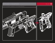
EOS PARTSIMPORTANTFIG. 16MAJOR EOS COMPONENTS1 2 3 451621617718208199142215111013121 FRKJFBLK – Freak Jr. Front (Black)2 FRKJB30BL – Freak Jr. Back3 QLK200NXTD – Q-Lock Feedneck4 EPY101PLT – EOS Body Shell5 Inner Body Assembly6 FRKI693AL - Freak .693 Insert7 EOS Circuit Board Assembly8 GRPEPY – Pro Touch Grips9 SCRN063632X0188BS – Grip Screws10 9-Volt Alkaline Battery11 SCRN0632X0188BS – Air Rail Lock Screw12 VLVDTAD – On/Off ASA13 HOS14BLK – 1/4” Macro-Line (Black)14 Max-Flo R Vertical Regulator with EOS Reg Cover15 SCRN1032X06870CS – Grip Frame Screws (2x)16 EOS Grip Frame Assembly17 EPY107ASM– EOS Trigger18 ION108 – Ball Detents (2x)19 ION117UPPRVSN – Breakbeam Vision Board20 EPY108 – Power Button21 SCRN1032X0375VO – Body Flat Cap Screw22 ION120 – Filter Screen800.922.2147 www.smartparts.com13
DISASSEMBLYEOS DISASSEMBLYFIG. 17EOS BOLT DISSASSEMBLYBOLT FIRE CHAMBER VOLUME BOLT PLUGCONTROLINSERTSThe EOS valve system has only one major moving part, making it simple to maintain, but this does notmean maintenance can be ignored. The EOS should be disassembled <strong>and</strong> cleaned any time it shows erraticperformance, becomes contaminated with paint, dirt or other debris, or for general maintenance after 3 or 4days of use.01 Unload <strong>and</strong> degas the EOS. Use a 5/16-inch allen wrench to unscrew <strong>and</strong> remove the bolt plug from theback of the EOS.02 Using a soft tool, like a wooden chopstick or plastic toothbrush, push the bolt, bolt stop <strong>and</strong> volumecontrol insert, if present, out the back of the EOS.03 Clean the interior of the body, the fire chamber, bolt <strong>and</strong> bolt stop with a clean cloth or paper towel.Inspect their o-rings for signs of damage such as rips or cuts <strong>and</strong> replace if necessary.04 Lubricate o-rings with SL33K marker lubricant. Slide the volume control insert into the fire chamber.Slide the bolt stop onto the bolt from the rear. Slide this assembly into the rear of the EOS. Screw thebolt plug into place with a 5/16-inch allen wrench – do not overtighten.This is all that is required for routine maintenance of the EOS. Further disassembly to inspect or replaceball detents <strong>and</strong> Vision or circuit board components may be done by following the advanced Disassembly<strong>instructions</strong> in this manual.14800.922.2147 www.smartparts.com
EOS VOLUME CONTROL INSERTSIMPORTANTIn order to provide more consistent velocity at higher rates of fire (above 10 bps) the EOS utilizes asmaller fire chamber volume than an Ion. To deliver full velocity, it operates at a slightly higher pressurerange (250 to 280 psi.) The smaller volume fire chamber can be recharged more quickly by the regulator,while the Ion bolt structure ensures that only a gentle low pressure burst of gas impacts againstthe paintball.In order to tune the EOS for optimal performance, three inserts are available, allowing four levels of <strong>adjustment</strong>to the volume of the fire chamber. These range from the largest volume (no insert,) to the greeninsert (second largest volume) to the blue insert (second smallest volume,) <strong>and</strong> finally to the silver insert(smallest volume.) An increase in operating pressure can be balanced with a decrease in fire chambervolume to maintain desired velocity.COMMON EOS CONFIGURATIONS:The Key to EOS performance is its reduced volume valve chamber. The smaller airspace in the EOS firechamber fills with gas faster, recharging the marker to deliver a full power shot sooner. This eliminatesshoot-down <strong>and</strong> allows the EOS to maintain consistent velocity even at high rates of fire. To optimizeperformance, the EOS includes three volume control inserts which allow you to fine-tune the amount ofairspace in its valve. Choosing the ideal insert <strong>and</strong> operating pressure level is a balancing act betweenlower pressures which allow for gentler, quieter operation, <strong>and</strong> higher pressures which allow for bettervelocity consistency at high rates of fire (10 bps <strong>and</strong> above.) It should be noted, that even at the high endof its pressure range, the EOS still operates at a lower pressure than many other “low-pressure” paintballmarkers. While some experimentation will be necessary to find the best setting for any given markerconfiguration <strong>and</strong> playing condition, the following guidelines will help select the proper volume insert.FIG. 18REMOVING VOLUME INSERTCHANGING VOLUME INSERTSChanging the volume inserts is simple. Degas<strong>and</strong> disassemble the EOS, following the Disassemblysection of this manual. The selectedinsert (or no insert) can be slid freely into theEOS fire chamber, <strong>and</strong> installed inserts can beremoved by reaching a finger into the insert<strong>and</strong> pulling it out. After installing the properinsert, the EOS can be reassembled by followingthe Reassembly section of this manual.The marker will then need to have its velocitymeasured <strong>and</strong> set (see the Velocity section ofthis manual.)Firebolt without QEV (St<strong>and</strong>ard Configuration) – Green (thinnest wall) – This is the st<strong>and</strong>ard EOSconfiguration, which will deliver a velocity of 285 fps at approximately 260 psi.Firebolt <strong>and</strong> a Quick Exhaust Valve (QEV) – Blue (middle size) Volume Insert – The volume of theblue insert will compensate for the effects of the QEV by slightly reducing the volume of gas in thefire chamber to provide 285 fps operation at approximately 260 psi.800.922.2147 www.smartparts.com15
VOLUME CONTROL INSERTSIMPORTANTCOMMON EOS CONFIGURATIONS (CON’T.):Reducing Pressure – No Insert – If the pressure at the desired velocity is above the EOS’s maximumof 280 psi, or temperatures are extremely high (which can soften pneumatics hoses) an increasein fire chamber volume to reduce operating pressure can be desirable. Setting up the EOSwith no inserts gives the maximum possible fire chamber volume.Indoor <strong>Operation</strong> – Silver Insert (thickest wall – smallest gas volume) – Many indoor paintball fieldsrestrict marker velocity to a maximum of 250 fps. By reducing the fire chamber volume even further,the silver insert allows this velocity to be reached while keeping the fire chamber pressure up in therange of 250-280 psi, protecting against velocity drop-off under rapid fire conditions.Some aftermarket Ion bolts, while compatible with the EOS, may increase the marker’s fire chambervolume to that point that even with the silver insert, there is too much airspace to operate within fieldvelocity limits without reducing air pressure below 250 psi. While the marker will operate at this lowerpressure, such a configuration will lose the high rate of fire velocity consistency benefits of the EOS lowvolumevalve system.16800.922.2147 www.smartparts.com
ADVANCED DISASSEMBLYEOS DISASSEMBLY01 0203Before beginning any maintenance or repairprocedures, completely unload <strong>and</strong> degas themarker following the <strong>instructions</strong> in the Degassingsection of this manual. Choose a clean,stable <strong>and</strong> protected work area where small partswill not be lost, such as a table covered with atowel to prevent parts from rolling. Remove thebarrel.Remove the bolt plug, bolt, firechamber <strong>and</strong> volume controlinsert from the EOS followingthe directions in the maintenance/disassemblysection ofthis manual. Use a 1/8-inchallen wrench to remove thebody flat cap screw, which isnormally concealed bythe barrel.Remove both left side (gauge side) grip screwswith a a 5/64-inch allen wrench <strong>and</strong> open theflexible wraparound grip. It is important to notethat the EOS’ grip screws are shorter than thoseof an Ion, <strong>and</strong> use of screws that are too longmay damage the marker’s circuit board. Removethe battery from the grip frame. Grasp the batteryin one h<strong>and</strong> <strong>and</strong> with the other h<strong>and</strong> grasp thebattery clip by the sides <strong>and</strong> unplug it from thebattery. Remove the right side grip frame screws<strong>and</strong> the flexible grip, as the upper right gripscrew may catch on the circuit board, making itsremoval difficult.Remove the front <strong>and</strong> rear gripframe screws using a 5/32-inchallen wrench.The EOS does not use the samelength grip frame screws asprevious Smart Parts Markers. Useof an incorrect length screw maycause internal damage, <strong>and</strong> void theEOS’ warranty.FIG. 19POWER BUTTON REMOVALDo not pull on the battery wires or circuit boardto unplug the battery as this may cause significantdamage.[ CONTINUED ON PAGE 18 ]During normal maintenance the power buttondoes not need to be <strong>and</strong> should not be removed.If it is damaged or requires replacement, grip itbetween a fingernail <strong>and</strong> thumbnail, <strong>and</strong> wiggleout, rear side first.800.922.2147 www.smartparts.com17
ADVANCED DISASSEMBLY (CONT.)DISASSEMBLY CONTINUED04050607Grasp the body with one h<strong>and</strong> <strong>and</strong> the gripframe with the other. Slowly pull the bodyaway from the grip frame, rolling it slightly tothe side, exposing the top of the grip frame<strong>and</strong> banjo fitting. It can be helpful to gentlypush on the bottom of the circuit board with athumb, helping it to slide upward.Remove the front banjo fitting from over thevertical adapter with a 1/8-inch allen wrench.The center of the banjo fitting will turn with thewrench, pivoting inside the rest of the fitting.Gently complete the process of separatingthe body from the grip frame.Take care to make sure that the circuitboard slides out of the grip frame withoutbeing strained, <strong>and</strong> that the batterywires <strong>and</strong> battery clip follow withoutcatching on the grip frame. Set the gripframe aside, <strong>and</strong> hold the body upsidedown (with the feedneck facing down.)Locate the Vision wiring harness. Thisgroup of four black wires runs fromthe lower circuit board to the Visioncircuit board in the body breech.Unplug the Vision wiring harness fromthe body end, being careful not tostrain the wires by tugging on them.As much as possible, pull on the connectordirectly.080910MAX-FLO RFor advanced maintenance ofthe EOS’ Max-Flo R verticalregulator, please download theMax-Flo R maintenance manualfrom the Support section ofSmartParts.com.Remove the remaining two banjo fittingsfrom the body with a 1/8-inchallen wrench.Keeping the body upside down, slidethe inner receiver components out ofthe body cover.Remove the Vision circuit board from the body breech<strong>and</strong> set aside carefully. This circuit board is shapedlike the letter C, <strong>and</strong> should come easily out of place.Take care to make sure that the infra-red emitter <strong>and</strong>detector (these look like clear LEDs) are not set onanything that can scratch them.18800.922.2147 www.smartparts.com
REASSEMBLYCLEANING AND REASSEMBLY01 02 0304 05Use a soft cloth toclean all parts ofpaint <strong>and</strong> dirt as wellas old oil or grease.Make sure the Vision circuitboard <strong>and</strong> its componentsare clean <strong>and</strong> undamaged.Make sure no dirt or debris isblocking the Vision holes in thebody breech – use a cottonswab to clean these openingsif necessary.Screw the fire chamber into the bodybreech. Place the Vision circuit boardinto its slot in the body breech. Itsplug should be on the side of theboard facing the rear of the marker.The clear emitter <strong>and</strong> detector shouldbe on the side facing the front of thebody breech.Slide the inner receiver assembly into thebody cover while holding both upside downto prevent the Vision circuit board fromfalling out, then plug the Vision wire harnessback into the Vision circuit board, <strong>and</strong>reconnect the center <strong>and</strong> rear banjo fittingsto the receiver, being careful not to crossthread them.Carefully pass the battery clip downinto the grip frame <strong>and</strong> slide the circuitboard into place before reinstalling theforward banjo fitting to its position inthe grip frame, again taking care not tocross-thread.06 07Reposition the body <strong>and</strong> grip frame together being carefulnot to pinch any wires or hoses. Reinstall the grip framescrews, <strong>and</strong> flat cap body screw, then tighten all three withan 1/8-inch allen wrench. Reinstall the battery, taking carenot to pinch the battery wires, <strong>and</strong> flexible the rubber grip<strong>and</strong> its screwsUse SL33K to grease the o-rings on the bolt,fire chamber <strong>and</strong> bolt plug, then reinstall thesecomponents.FIG. 20 INNER BODY ASSEMBLY128 912131011143 45 171516618 1971 MRK100 – Inner Body2 ION209 – Firebolt3 EPY111 – EOS fire Chamber4 EPYINTLG – Green Volume Control Insert5 EPYINTLM – Blue Volume Control Insert6 EPYINTLS – Silver Volume Control Insert7 EPY104 – Back Plug8 ORN01790UR – SFT O-Ring9 ORN01770HN – Rear Breech O-Ring10 ION108 – Ball Detent (2x)11 ION117UPRVSN – Break-Beam Vision Board12 ORN01590CUR – Firebolt Bumper13 ORN0162070HN – Firebolt Middle O-Ring14 ORB01070UR – Firebolt Rear O-RIng15 ORN01470UR – Fire Chamber Inner O-Ring16 ORN01870BU – Fire Chamber Outer O-Ring17 ORN01770BU – Plug/Chamber O-Ring18 ORN01870BU – Supply Seal O-Rings (2x)19 ORN02270BU – Rear O-Ring800.922.2147 www.smartparts.com19
SOLENOID VALVEDISASSEMBLY AND MAINTENANCEFIG. 21SOLENOID EXPLODED VIEW1 BUM006 – Foam Disk2 ION118 – Vision Wiring Harness3 ELB1032X18PTCBNJ – Banjo Fitting4 ELB1032X532PTCBNJ – Banjo Fitting5 HOS4MMBLK4025 – Black EOS Hose6 EPY117LOVUSASM – EOS Circuit Board7 HOS4MMBLK875 – Black EOS Hose8 ION131 & ION132 – Barbed Banjo Fitting9 Armature10 SOL3UPG – EOS Solenoid Coil11 Solenoid Head12 Solenoid BracketThe solenoid valve is the heart of the EOS.When the circuit board supplies it with power, itredirects gas flow to allow the bolt to close <strong>and</strong>fire the marker. During normal maintenance thesolenoid valve should not need to be disassembled.However, if it becomes clogged ordevelops a leak it is simple to disassemble forcleaning or repair. When replacing hoses orsolenoid valve components, EOS or Epiphanyrated models must be used. The EOS solenoidvalve can be identified by its red protective coilwrap with black Ion logo.01 02 03 04 05 0607Follow the advanceddisassembly <strong>instructions</strong> toremove the circuit board fromthe EOS. Using a 3/32-inchallen wrench, hold the circuitboard <strong>and</strong> solenoid body thenpry the bracket from the backof the solenoid valve. Place thewrench between the bracket <strong>and</strong>the upper, black section of thesolenoid valve body.Do not pry against the redsolenoid coil or the EOS heatshrink coil protector, as thiswill cause damage.After the solenoidbracket isremoved, liftthe solenoidhead straightout, wiggling ifnecessary toloosen it.Tip the circuitboard over<strong>and</strong> allow thearmature to fallinto your h<strong>and</strong>.The armaturefits loosely in thecenter of the coil,<strong>and</strong> should fallout easily.Clean the inside ofthe solenoid with acotton swab, <strong>and</strong>clean the armaturewith a soft cloth,removing anydebris, oilor grease.Reassemble thesolenoid valve.Place the armatureback in the coilwith the armaturefacing down.Push the solenoidhead back intothe solenoid valvebody, makingsure that the longhoses <strong>and</strong> Visionwiring harnessare aligned on thesame side of thecircuit board asthe trigger switch.Replace the solenoid bracket,pressing it back into place. Thebent bracket section goes over thebottom side of the solenoid.A very light layer of SL33Klubricating the hose barb willmake the installation of new hoseseasier, but extreme care must betaken that no excess grease isable to enter the solenoid valve.Holding the solenoid head witha box end or small adjustablewrench over the hose barb willallow the hose to be pulled awayfrom the wrench which will holdback the solenoid head.20800.922.2147 www.smartparts.com
BALL DETENTSINSPECTION, CLEANING AND REPLACEMENT01 02 03 04 05Degas <strong>and</strong> disassemblethe marker (see theAdvanced Disassemblysection.)Look into the body. The tipof each ball detent shouldextend approximately 1/16of an inch into the breecharea. If either detent doesnot reach this far intothe breech, it should bereplaced.To avoid risk of eyeinjury, even while wearinggoggles, do not look intothe barrel or breech of anassembled marker.Reach a finger into the body<strong>and</strong> press out against thedetent. It may then be removedby prying or grippingwith fingernails, needlenosedpliers, an o-ring pickor even a 0.050-inch allenwrench. Inspect the balldetents for tears or damage.If they are damaged, replacethem. If not, clean them witha soft cloth, <strong>and</strong> clean thedetent openings in the bodybreech with a cotton swab.Reinstall the detents bypressing them into placewith a thumb.Reassemble the marker.FIG. 22PRYING OUT DETENT800.922.2147 www.smartparts.com21
TROUBLESHOOTINGIMPORTANTEOS IS LEAKING INTERNALLY.— Pneumatic hoses may be loose, damaged or not fully connected. Replace hoses with Smart Parts EOShoses only.— One or more of the banjo fittings may be loose or have a damaged seal. Inspect <strong>and</strong> tighten fittings.Replace if necessary with Smart Parts Ion/EOS banjo fittings only.— Solenoid armature is damaged or over-pressurized. Make sure operating pressure is under 280psi.Inspect solenoid valve <strong>and</strong> replace armature if necessary.EOS IS LEAKING DOWN THE BARREL.— One or more of the bolt o-rings <strong>and</strong>/or the fire chamber o-rings are damaged. Inspect <strong>and</strong> replace,making sure to clean <strong>and</strong> lubricate these parts following the Disassembly section of this manual.EOS IS LEAKING FROM THE MACROLINE AIR FITTINGS.— Macroline may not be fitted properly. Degas the marker <strong>and</strong> make sure the macroline is properlylocked into its fittings. If the macroline shows signs of damage, replace it with a new piece. Be sure tocut clean ends, <strong>and</strong> if using diagonal cutters, dress the end with a small needle file to be certainit is not crimped partially closed.EOS IS LEAKING FROM IN OR AROUND THE REGULATOR.— Gas may occasionally vent near the bottom of the Max-Flo R vertical regulator, especially when usingCO2. This is a normal function as the regulator protects your marker <strong>and</strong> does not indicate a problem.— The ASA o-ring at the top of the regulator may be damaged. Remove the regulator to inspect. If this o-ring is damaged it may be replaced with a st<strong>and</strong>ard CO2 bottle o-ring available at most paintball shops.— The regulator seat may be contaminated <strong>and</strong>/or damaged. Download the Max-Flo R manual from thesupport section of SmartParts.com.EOS EXHIBITS FIRST SHOT DROP-OFF (FSDO).— FSDO is a low velocity, or non-firing first shot followed by normal shooting, <strong>and</strong> is often caused bydebris in the bolt or a poorly lubricated bolt. Clean the bolt, body breech, fire chamber <strong>and</strong> boltstop, <strong>and</strong> lubricate them with SL33K (See the Disassembly section of this manual.)— FSDO can also be caused by too low of a dwell setting. Follow the procedure for optimal dwell <strong>adjustment</strong><strong>and</strong> or increase the dwell setting (see the Electronic Adjustment section of this manual.)22800.922.2147 www.smartparts.com
TROUBLESHOOTINGIMPORTANTEOS HAS INCONSISTENT VELOCITY OR DROPS SIGNIFICANTLY DURING RAPID FIRING.— Barrel to paint match may not be correct. Check the fit of the paintballs to the barrel (see Paint sectionof this manual.) If it is a poor fit, switch paintballs, barrel, or barrel insert for a better fit.— Gas source could be low. Fill gas source <strong>and</strong> make sure valve is turned on.— Battery may be low. This will be most noticeable with velocity dropping, <strong>and</strong> then entire shots not firingduring rapid fire. Replace with a name br<strong>and</strong> alkaline 9-volt battery.— Regulator seat may be contaminated <strong>and</strong>/or damaged. Inspect <strong>and</strong> clean the regulator seat (downloadthe Max-Flo R manual at smartparts.com.) If the regulator seat is damaged, it may be flipped over touse the back side. If both sides are damaged, it must be replaced.— Pressure may be low. Switch to a smaller volume fire chamber insert <strong>and</strong> increase operating pressure.— SFT o-ring may be damaged, swollen or missing. Inspect <strong>and</strong> if necessary replace the SFT o-ring(see Assembly diagram.)— Liquid CO2 may be entering the regulator. Only use CO2 with an anti-siphon tank in the ASA, or ast<strong>and</strong>ard tank placed vertically in a pack with a remote. Alternatively, switch to compressed air.EOS WILL TURN ON BUT WILL NOT FIRE.— Battery may be low or dead. Replace with a name br<strong>and</strong> alkaline 9-volt battery.— Solenoid valve may be blocked with debris. Disassemble solenoid, clean armature, <strong>and</strong> inside solenoidbody, then reassemble without lubricant (see Solenoid Disassembly/Maintenance sectionof this manual.)— One or more of the trigger set screws may be mis-adjusted. The trigger switch should be heard clickingwhen the trigger is pulled with the EOS turned off. Back pre <strong>and</strong> post-travel screws out untiltrigger will activate the marker then set properly (see the Trigger section of this manual.)— Trigger switch may be damaged. - Visit your nearest Smart Parts Authorized Dealer or contact SmartParts for circuit board repair or replacement.— Regulator output pressure may be too high (above 280 psi.) Decrease the pressure (see VelocityAdjustment section of this manual.) If pressure slowly rises after being set, inspect, clean <strong>and</strong> ifnecessary replace the regulator seat (see Regulator section of this manual.)— Liquid CO2 may be entering the regulator. Only use CO2 with an anti-siphon tank in the ASA, or ast<strong>and</strong>ard tank placed vertically in a pack with a remote. Alternatively, switch to compressed air.TRIGGER WILL NOT RESET TO THE FORWARD POSITION— The trigger activation point screw may be adjusted too far toward the rear of the marker. Follow thetrigger <strong>adjustment</strong> <strong>instructions</strong> <strong>and</strong> adjust this screw further in to the trigger.800.922.2147 www.smartparts.com23
TROUBLESHOOTINGIMPORTANTTHE EOS IS BREAKING PAINT.— Battery may be low or dead. Replace with a name br<strong>and</strong> 9-volt alkaline battery.— Ball detents may be worn or damaged. Inspect <strong>and</strong> if necessary replace (see Ball Detent section ofthis manual.)— Barrel to paint match may not be correct. Check the fit of the paintballs to the barrel (see Paint sectionof this manual.) If it is a poor fit, switch paintballs, barrel, or barrel insert for a better fit.— Vision mode may be turned off. This will be indicated by a double-blink pattern on the power button.Turn Vision on by pressing the power button.— Paint or debris may be partially blocking the Vision eye from properly “seeing” the breech. Removethe Vision circuit board. Carefully clean the infrared emitter <strong>and</strong> detector with a damp, soft cloth <strong>and</strong>clean the Vision ports in the body breech with a cotton swab (see Disassembly section of this manual.)— Wiring harness may be damaged. Check to make sure that the wiring harness running from the solenoidcircuit board in the grip frame to the Vision circuit board in the body is plugged in at both ends,<strong>and</strong> is not bent, crimped, broken or frayed (see Disassembly section of this manual.)— Vision board may be damaged from improper installation. Replace Vision board (see Disassemblysection of this manual.)— Liquid CO2 may be entering the regulator. Only use CO2 with an anti-siphon tank in the ASA, or ast<strong>and</strong>ard tank placed vertically in a pack with a remote. Alternatively, switch to compressed air.ROF IS TURNED UP ALL THE WAY AND EOS WILL NOT FIRE RAPIDLY.— The ROFDelay setting of the EOS circuit board controls how long the marker must wait between shots.Increasing the delay (yellow blinking) will slow the EOS down. Decreasing the delay (red blinking) willallow it to shoot faster (see Electronic Adjustment section of manual.)— The EOS’s break-beam Vision system prevents it from firing until a paintball has been properlyloaded. Non-motorized or agitating hoppers will not feed paintballs as quickly as a modern force-feedloader, resulting in a restricted rate of fire.24800.922.2147 www.smartparts.com
TROUBLESHOOTINGIMPORTANTA REFEREE SAYS THE EOS IS SHOOTING TOO FAST (BALLS PER SECOND)— Some tournaments <strong>and</strong> paintball fields limit the rate of fire allowed. Many tournaments, for example,limit players to a maximum of 15 balls per second. The marker’s rate of fire can be limited byincreasing the ROFDelay setting (see Electronic Adjustment section of manual <strong>and</strong> the CPS Table.)REFEREE SAYS THE EOS IS SHOOTING TOO FAST (MORE THAN 1 SHOT PER TRIGGER PULL)— Many tournaments, scenario games <strong>and</strong> paintball fields limit players to shooting in true semi-automaticmode. Set the marker’s firing mode to 0-Semi-Automatic (see Electronic Adjustment sectionof manual.)TECH SUPPORTU.S. EAST COASTSmart Parts, Inc.100 Station StreetLoyalhanna, PA 15661800.992.2147U.S. WEST COASTWest Coast Repair Center27326 Jefferson Ave #2Temecula, CA 92590951.296.1000U.K.Unit A6Larkfield Trading EstateNew Hythe LaneAylesford,KentME20 65W++40 (0) 1622.719.995WARRANTYSmart Parts warrants for one (1) year to initial retail purchaser that the paintball marker <strong>and</strong> regulator are free from defects in materials<strong>and</strong> workmanship. Disposable parts (batteries, o-rings, seals, springs, etc.) are not warranted. The valve assembly is warrantedfor six (6) months. The solenoid <strong>and</strong> electronics on the marker are warranted for six (6) months, plus an additional warranty of sixmonths for electronic parts only (installation <strong>and</strong> labor are not included.) This warranty does not cover surface damages (scratches<strong>and</strong> nicks), misuse, improper disassembly <strong>and</strong> re-assembly, attempts made to drill holes or remove metal from the external surfaceswhich could degrade performance <strong>and</strong> reduce pressure safety factors of the marker. Do not make changes to the basic marker partswithout written approval. The only authorized lubricant for the marker is SL33K Lubricant. Use of any other lubricant could result invoiding your warranty. Paintball markers are non-refundable. This warranty is limited to repair or replacement of defective parts withthe customer to pay shipping costs. This warranty is effective only if the customer returns the warranty registration card enclosed withthe marker. The warranty is non-transferrable. Do not attempt to alter the trigger assembly in any way, as this will void your SmartParts Inc. warranty. Trigger alteration of any kind may result in serious injury. Replacement or alteration of the Max-Flo R Verticalregulator will void warranty <strong>and</strong> may result in serious damage <strong>and</strong> or injury.Additional support <strong>and</strong> downloadable productmanuals are available through our web site,www.smartparts.com.800.922.2147 www.smartparts.com25
CPS TABLEThis table provides a cross reference between EOS settings <strong>and</strong> the resulting maximumpossible cycles per second. To limit an EOS to shoot at or below 15 balls per second,look up its dwell setting in the dwell column, then look across to find a CPS value that iscomfortably below 15, <strong>and</strong> up to find the appropriate ROFDelay value needed.Stock Dwell Value: 52 clicks from bottomStock ROFDelay Value: 50 clicks from bottomROFDELAYDWELLNOTE: THE EPIPHANY EOS CIRCUIT CIRCUIT BOARD BOARD WILL WILL FIRE NOT AT A FIRE MAXIMUM AT RATES OF ABOVE 17 CYCLES 17 CYCLES PER SECOND. PER SECOND.Clicks 0 5 10 15 20 25 30 35 40 45 50 55 60 65 70 75 80 85 88Clicks Ms 8 10.5 13 15.5 18 20.5 23 25.5 28 30.5 33 35.5 38 40.5 43 45.5 48 50.5 520 25.0 17.0 17.0 17.0 17.0 17.0 17.0 17.0 17.0 17.0 17.0 17.0 16.5 15.9 15.3 14.7 14.2 13.7 13.2 13.03 26.5 17.0 17.0 17.0 17.0 17.0 17.0 17.0 17.0 17.0 17.0 16.8 16.1 15.5 14.9 14.4 13.9 13.4 13.0 12.76 28.0 17.0 17.0 17.0 17.0 17.0 17.0 17.0 17.0 17.0 17.0 16.4 15.7 15.2 14.6 14.1 13.6 13.2 12.7 12.59 29.5 17.0 17.0 17.0 17.0 17.0 17.0 17.0 17.0 17.0 16.7 16.0 15.4 14.8 14.3 13.8 13.3 12.9 12.5 12.312 31.0 17.0 17.0 17.0 17.0 17.0 17.0 17.0 17.0 16.9 16.3 15.6 15.0 14.5 14.0 13.5 13.1 12.7 12.3 12.015 32.5 17.0 17.0 17.0 17.0 17.0 17.0 17.0 17.0 16.5 15.9 15.3 14.7 14.2 13.7 13.2 12.8 12.4 12.0 11.818 34.0 17.0 17.0 17.0 17.0 17.0 17.0 17.0 16.8 16.1 15.5 14.9 14.4 13.9 13.4 13.0 12.6 12.2 11.8 11.621 35.5 17.0 17.0 17.0 17.0 17.0 17.0 17.0 16.4 15.7 15.2 14.6 14.1 13.6 13.2 12.7 12.3 12.0 11.6 11.424 37.0 17.0 17.0 17.0 17.0 17.0 17.0 16.7 16.0 15.4 14.8 14.3 13.8 13.3 12.9 12.5 12.1 11.8 11.4 11.227 38.5 17.0 17.0 17.0 17.0 17.0 16.9 16.3 15.6 15.0 14.5 14.0 13.5 13.1 12.7 12.3 11.9 11.6 11.2 11.030 40.0 17.0 17.0 17.0 17.0 17.0 16.5 15.9 15.3 14.7 14.2 13.7 13.2 12.8 12.4 12.0 11.7 11.4 11.0 10.933 41.5 17.0 17.0 17.0 17.0 16.8 16.1 15.5 14.9 14.4 13.9 13.4 13.0 12.6 12.2 11.8 11.5 11.2 10.9 10.736 43.0 17.0 17.0 17.0 17.0 16.4 15.7 15.2 14.6 14.1 13.6 13.2 12.7 12.3 12.0 11.6 11.3 11.0 10.7 10.539 44.5 17.0 17.0 17.0 16.7 16.0 15.4 14.8 14.3 13.8 13.3 12.9 12.5 12.1 11.8 11.4 11.1 10.8 10.5 10.442 46.0 17.0 17.0 16.9 16.3 15.6 15.0 14.5 14.0 13.5 13.1 12.7 12.3 11.9 11.6 11.2 10.9 10.6 10.4 10.245 47.5 17.0 17.0 16.5 15.9 15.3 14.7 14.2 13.7 13.2 12.8 12.4 12.0 11.7 11.4 11.0 10.8 10.5 10.2 10.148 49.0 17.0 16.8 16.1 15.5 14.9 14.4 13.9 13.4 13.0 12.6 12.2 11.8 11.5 11.2 10.9 10.6 10.3 10.1 9.951 50.5 17.0 16.4 15.7 15.2 14.6 14.1 13.6 13.2 12.7 12.3 12.0 11.6 11.3 11.0 10.7 10.4 10.2 9.9 9.854 52.0 16.7 16.0 15.4 14.8 14.3 13.8 13.3 12.9 12.5 12.1 11.8 11.4 11.1 10.8 10.5 10.3 10.0 9.8 9.657 53.5 16.3 15.6 15.0 14.5 14.0 13.5 13.1 12.7 12.3 11.9 11.6 11.2 10.9 10.6 10.4 10.1 9.9 9.6 9.560 55.0 15.9 15.3 14.7 14.2 13.7 13.2 12.8 12.4 12.0 11.7 11.4 11.0 10.8 10.5 10.2 10.0 9.7 9.5 9.363 56.5 15.5 14.9 14.4 13.9 13.4 13.0 12.6 12.2 11.8 11.5 11.2 10.9 10.6 10.3 10.1 9.8 9.6 9.3 9.266 58.0 15.2 14.6 14.1 13.6 13.2 12.7 12.3 12.0 11.6 11.3 11.0 10.7 10.4 10.2 9.9 9.7 9.4 9.2 9.169 59.5 14.8 14.3 13.8 13.3 12.9 12.5 12.1 11.8 11.4 11.1 10.8 10.5 10.3 10.0 9.8 9.5 9.3 9.1 9.072 61.0 14.5 14.0 13.5 13.1 12.7 12.3 11.9 11.6 11.2 10.9 10.6 10.4 10.1 9.9 9.6 9.4 9.2 9.0 8.875 62.5 14.2 13.7 13.2 12.8 12.4 12.0 11.7 11.4 11.0 10.8 10.5 10.2 10.0 9.7 9.5 9.3 9.0 8.8 8.778 64.0 13.9 13.4 13.0 12.6 12.2 11.8 11.5 11.2 10.9 10.6 10.3 10.1 9.8 9.6 9.3 9.1 8.9 8.7 8.681 65.5 13.6 13.2 12.7 12.3 12.0 11.6 11.3 11.0 10.7 10.4 10.2 9.9 9.7 9.4 9.2 9.0 8.8 8.6 8.584 67.0 13.3 12.9 12.5 12.1 11.8 11.4 11.1 10.8 10.5 10.3 10.0 9.8 9.5 9.3 9.1 8.9 8.7 8.5 8.487 68.5 13.1 12.7 12.3 11.9 11.6 11.2 10.9 10.6 10.4 10.1 9.9 9.6 9.4 9.2 9.0 8.8 8.6 8.4 8.390 70.0 12.8 12.4 12.0 11.7 11.4 11.0 10.8 10.5 10.2 10.0 9.7 9.5 9.3 9.0 8.8 8.7 8.5 8.3 8.226800.922.2147 www.smartparts.com
800.922.2147 100 Station St. Loyalhanna, PA 15661 www.smartparts.com manual version 1.0