Invert Mini Manual - P8ntbox
Invert Mini Manual - P8ntbox
Invert Mini Manual - P8ntbox

Create successful ePaper yourself
Turn your PDF publications into a flip-book with our unique Google optimized e-Paper software.
MINI MANUAL 08_v2.indd 1 9/8/08 3:52:49 PM
No part of this document may be copied or reproduced in any form or by any means without the priorwritten consent of <strong>Invert</strong> Paintball and KEE Action Sports, its assigns and/or its distributors.Notice is hereby given that this manual is part of the article owned in whole by KEE Action Sports, its assigns and/or its distributors, knownas indicated. In this manual and drawings. All rights of manufacture and reproduction of such articles or any part thereof are reserved by KEEAction Sports, its assigns and/or its distributors. Neither said article nor any part thereof may be manufactured or reproduced except by writtenauthorization from KEE Action Sports, its assigns and/or its distributors. All proprietary rights and information are the sole property of KEEAction Sports, its assigns and/or its distributors.<strong>Invert</strong> Paintball brand for all intents and purposes is owned wholly by KEE Action Sports. KEE Action Sports delivers this marker with the understandingthat KEE Action Sports, its assigns and/or its distributors assumes no responsibility for its resale or safe handling. Serious injuryor death may occur if mishandled, abused, or the safety instructions are ignored. KEE Action Sports, its assigns and/or its distributors assumesno responsibility for physical injury or property damage resulting from its use.KEE Action Sports, its assigns and/or its distributors, makes no warranties with respect to this documentation and disclaims any implied warrantiesof merchantability or fitness for a particular purpose. The information in this document is subject to change without notice. KEE ActionSports, its assigns and/or distributors assumes no responsibility for any errors that may appear in this document.This is not a toy. Misuse may cause serious injury or death. The user and any person within range must wear eye protection designed specificallyfor paintball use. Recommend 18 years of age or older to purchase. Persons under 18 years of age must have adult supervision. Obey alllocal, state and federal laws. Follow the rules of safe paintball marker handling.MINI MANUAL 08_v2.indd Sec1:2 9/8/08 3:52:51 PM
TABLE OF CONTENTS-Section1. Rules for Safe Marker Handling...........................................................................pg.42. Introduction and Specifications..........................................................................pg.43. Battery Replacement and Life Indicator.............................................................pg.54. Compressed Air/Nitrogen Supply.......................................................................pg.65. Basic Operation...................................................................................................pg.66. Firing the MINI.....................................................................................................pg.77. Break beam Eyes Operation................................................................................pg.88. Unloading the MINI..............................................................................................pg.89. Regulator and Velocity Adjustments...................................................................pg.810. Optimus Board....................................................................................................pg.1011. Trigger Adjustments.............................................................................................pg.1312. <strong>Mini</strong> Assembly/Disassembly and Maintenance................................................pg.1313. Storage and Transportation................................................................................pg.2014. Trouble Shooting Guide......................................................................................pg.2115. Diagram and Parts List.......................................................................................pg.2616. Warranty Information..........................................................................................pg.29MINI MANUAL 08_v2.indd Sec1:3 9/8/08 3:52:52 PM
3. BATTERY REPLACEMENT AND LIFE INDICATORThe MINI requires a single 9-volt battery as the electronic power source. Theuse of long life batteries is recommended. The 9-volt battery is located in thefront fore-grip in front of the trigger guard. The battery is accessed throughthe removable left side plate on the front fore-grip.Confirm that the marker is Off. Remove the screw at the bottom that securesthe left side plate in the front fore–grip. If there is already a battery in thefore-grip, gently disconnect the battery from the battery harness, and thenconnect a fresh 9-Volt battery to the harness. Carefully re-insert battery andharness back into the battery compartment with the harness pointed downtowards the bottom of the grip. Make sure that there are no abrupt kinks andthe wires are comfortably placed, do not force them into place. Then re-installthe fore-grip side plate and screw.INVERT MINI SPECIFICATIONSModel- <strong>Invert</strong> <strong>Mini</strong>Barrel- 12” portedCaliber-68Action- Semi auto, Ramping, and Full autoAir source- Compressed airBattery- One 9 voltCycle Rate- 20 BPSMain Body material- AluminumThe MINI also has a Battery Life indicator. If in standard operation and theLED flashes with a GREEN color then the battery is GOOD, if the LED is OR-ANGE the battery is fairly depleted and you should change battery soon, orif the LED is RED then there is less than 20% of the full battery strengthremaining and battery should be replaced immediately.Accuracy Range- 150 + ftWeight– 1.99 lbsINCLUDED WITH YOUR MINI-12” Barrel (.691 bore)-Allen Keys-Spare Parts-Barrel PlugNotes:- Some rechargeable batteries are too large for the MINI battery compartment. If they don’t fit,please don’t force them as this may damage the MINI.-One 9 Volt Battery (installed)- The stock circuit board does not keep user defined settings. You must change the batteryquickly to keep your settings. If the battery is not changed quickly the Circuit board will go backto the factory default settings.WWW.INVERTPAINTBALL.COM5MINI MANUAL 08_v2.indd Sec1:5 9/8/08 3:52:52 PM
4. COMPRESSED AIR/NITROGEN SUPPLYThe MINI is designed to work with Compressed Air/Nitrogen Only. Do Notuse CO2, as it will damage your <strong>Mini</strong>.Consult the place where you purchased your MINI, or a recognized andcompetent air smith, for instruction in the safe handling of compressed-aircylinders before purchasing or connecting one to your MINI.The MINI utilizes a fully functional regulator at the bottom of the grip framethat doubles as an ASA (Air Source Adaptor) or receiver for a standardthreaded pre-set output compressed air system. It is strongly recommendedthat a very high-flow “low pressure” (350-450 psi) fixed-output system isutilized as an air source for your MINI. If you are using an adjustable outputregulator system, the output pressure should be between 350-450 psi.BEFORE PRESSURIZING YOUR MINI- Check to make sure that you and anyone within range are wearing eyeprotection designed specifically for paintball.- Double check that all screws are tightened and no parts are loose beforeinstalling your tank.- Ensure you have a barrel plug, barrel sock or other specifically designedbarrel-blocking device in place.- Make sure there are no paintballs in the marker and that the <strong>Mini</strong> isturned Off.- Air can now be applied and the marker will become pressurized.5. BASIC OPERATION- Safety and safe marker handling are the most important aspects of paintballsports. Please practice each of the following steps with an unloaded markerbefore attempting to charge your marker with compressed air and paintballs.-Do not install compressed air or load paintballs into your MINI until you feelcompletely confident with your ability to handle your MINI safely.-Keep your finger out of the trigger guard and away from the trigger; point themuzzle of the marker in a safe direction at all times. Keep the marker turnedoff until ready to operate. The MINI uses an On-Off button for one of its safetydevices.-Always keep your MINI pointed in a safe direction. Always use a barrel plugor barrel blocking device. Always use ASTM approved paintball specific eyeprotection in any areas where paintball markers may be discharged. Rememberthat the ultimate safety device is you, the operator.SWITCHING ON YOUR MINITo switch the MINI On, locate the Power Button on the back side of the frontfore-grip, in front of the trigger guard and directly under the LED. Push andhold the button for 2 seconds and the LED light will turn GREEN and then toRED. Release button and the LED will intermittently flash green indicatingthat the marker is now ON and LIVE.Notes:- Remember compressed air or nitrogen systems can be extremely dangerous if misused orimproperly handled. Use only cylinders meeting D.O.T. or regionally defined specifications. Donot perform any work to your tank or tank regulator.- Never disassemble your tank or tank regulator. Only a qualified and trained technicianshould perform work on your tank and tank regulator.- Never add any lubricants or greases into the fill adapter on your tank regulator or into the<strong>Mini</strong>’s regulator6MINI MANUAL 08_v2.indd Sec1:6 9/8/08 3:52:53 PM
7. BREAK BEAM EYES OPERATIONThe MINI uses a break beam eye system to determine the absence or presenceof a ball for the purposes of reduced paint breakage and optimumrates of fire. The MINI board is pre-programmed to activate the eye systemeach time the marker is powered up.To turn the eyes Off, ensure that there are no paintballs in the MINI breech orfeed-neck, make sure the marker is switched Off, and then while pulling andholding the trigger, turn the marker on. A quick double blinking green LEDwill indicate that the eye system has been deactivated.To turn the eyes back on, simply tap the power button one time quickly.A slow consistent single flashing green LED indicates that the eyes are ONwith no ball in the breech and a rapid flashing green LED indicates that thereis a ball in the breech.For optimal performance of the MINI eyes, keep the inside of the MINI breechclean and clear of broken paint, paint residue, or other debris.Although the eyes can be cleaned via cleaning the breech of the MINI marker,if the eyes need to be accessed please follow the steps outlined in theMain Body Assembly section of this manual.8. UNLOADING THE MINI- Always keep your <strong>Mini</strong> pointed in a safe direction and always keep yourprotective eye, face and ear wear on until marker is completely unloaded.- Be sure your finger is away from the trigger area.- Place the barrel plug, sock, or barrel blocking device into the end ofthe barrel.- Turn the <strong>Mini</strong> Off by pressing and holding the On/Off button. The Led willturn from green to red. Observe the light to make sure it is no longer lit.- Remove your pressurized gas source by slowly and carefully unscrewing it.- If you are using an electronic loader make sure loader is completelyturned Off.- Slightly tilt the marker so that the loader is lower than the body.- Remove the loader by undoing the clamp and spinning it in a clockwisedirection and gently lifting it.- Read the pressure gauge and make sure the pressure reads 0 PSI.- DO NOT look down the barrel but look down the feed neck to makesure there are no paintballs in the breech.- Remove the barrel from the marker.- Make sure there are no more paintballs remaining in the barrel.9. REGULATOR AND VELOCITY ADJUSTMENTThe MINI utilizes a fully functional MINI Bottom-line Regulator at the bottomof the grip frame that doubles as an ASA adaptor/receiver for a standardthreaded pre-set output compressed air system. This unique regulator systemchannels air through a chamber in the grip frame eliminating the needfor external macro line and fittings. The MINI Bottom-line Regulator controlsthe amount of air pressure going from your compressed air system into themaker itself.The MINI regulator should be pre-set at 200 PSI as this is the best operatingpressure for firing the marker. However, if over time you do need to adjustthe pressure only use the Regulator Adjuster Screw on the front of your MINIBottom-line Regulator.8MINI MANUAL 08_v2.indd Sec1:8 9/8/08 3:52:54 PM
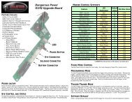
10. OPTIMUS BOARDThe <strong>Invert</strong> MINI is driven by an Optimus Board. The Optimus Boardfeatures several modes and functions that are listed below. The OptimusBoard is located inside the front fore-grip.FUNCTIONS, MODESThe MINI must be Off to begin managing functions. While the MINI is Off,press the Function Key to access one of the 5 different functions and makeadjustments.Before adjusting Functions, remove the propellant source from the MINI andinstall barrel blocking device.The Optimus Board inside your MINI features 5 functions. It uses a 3 colorLED indicator on the backside of the front fore-grip to indicate functions andmodes during programming.To access and set the Optimus Board, place MINI on a flat surface withmuzzle pointing to the left. Using a 5/64” Allen wrench, remove the screwthat secures the left side plate to the front fore–grip. This will expose thebattery and the Optimus Board. Please locate the (A) Function Key, whichis a small black button on the rear of the board, to the left and slightly abovethe Power Button (B), marked DIP (see illustration). It is not necessary toremove the board from the housing in order to manage settings.1. Firing Modes (Solid Red LED)2. Rate of Fire (Solid Green LED)3. Dwell (Solid Orange LED)4. BIP Delay (Flashing Red LED)5. Ramping Point (Quick-Flashing Green LED)- Once you push the Function Key the appropriate amount of times to get intothe desired function, the LED will flash a specific color per the descriptionsbelow followed by a number of flashes which will indicate the current settingin that function.- To increase or decrease a setting of a function, use the Power Button(B) andFunction Key(A). The Power Button will decrease a setting by one every timeit is pushed. The Function Key will increase a setting by one every time it ispushed. The setting can be changed when the function you select has a solidlight which will come before the board flashes the current setting.Example: Press the Function Key 1 time and you will be in “Function 1” whichis “Firing Modes” or press the Function Key 3 times and you will be in“Function 3” which is “Dwell”.FIRING MODES-WILL BE INDICATED BY SOLID RED LED10To get into the Firing Mode Function, make sure the Power is Off, then pushthe Function Key one time and LED will turn to Red and then flash to indicatethe Firing Mode that it is currently in. For example the Default mode is Semi-Auto which will be demonstrated by 1 flash.MINI MANUAL 08_v2.indd Sec1:10 9/8/08 3:52:56 PM
THERE ARE 4 FIRING MODES:-Semi-Auto/NPPL (1 Flash) – One shot per trigger pull. Max ROF capped at20 BPS.-Ramping/PSP (2 Flashes) – The MINI will operate in semi-auto mode for thefirst 3 shots; then if player achieves the minimum trigger pull as defined by theRamping Point value in Function 5, which is defaulted to 4 trigger pulls persecond for this mode, the MINI will ramp to the Rate of Fire value in Function2, which is defaulted to 13 shots per second for this mode.- Full-Auto/NXL (3 Flashes) – The MINI will operate in semi-auto mode for thefirst 3 shots; then pull and hold trigger on the 4th shot, and the MINI will firefull-auto at the Rate of Fire value in Function 2, which is defaulted to 13 shotsper second for this mode.-Ramping/Millen. (4 Flashes) – The MINI will operate in a semi-auto modeuntil player achieves the minimum trigger pull as defined by the RampingPoint value in Function 5, which is defaulted to 6 trigger pulls per secondfor this mode. At that point, and as long as 6 trigger pulls per second aremaintained, the MINI will ramp to the Rate of Fire value in Function 2, whichis defaulted to 12 shots per second for this mode.MAX RATE-OF-FIRE (ROF)-WILL BE INDICATED BY SOLID GREEN LEDTo get into the ROF Function, make sure Power is Off, then push FunctionKey two times and LED will turn to a solid Green and then flash to indicatethe Rate of Fire (1-20) that you are currently using. Default is 15 Bps (balls persecond). To adjust ROF push the Function Key two times and while the LEDis lit a solid Green use either the Function Key (to toggle up or increase yourROF) or the Power Button (to decrease the ROF).Example– To start you will be in a Default setting of 15 BPS. Push the FunctionKey twice to get into ROF Mode. While the LED is lit a solid Green, pressthe Function Key 5 times to take you to 20 BPS. Upon releasing the FunctionKey, the LED should then blink 20 times indicating your new Rate of Fire.The easy way to know your rate of fire: number of flashes divided by two thenadd ten.Note: After modes 2 through 4 are selected, it is possible to raise or lower both the Rate of Fireand Ramping Point values in case the tournament rules change.Example: 15 flashes / 2 = 7.5, 7.5 + 10 = 17.5 BPSTo cycle through the Firing Modes you use both the Power Button and FunctionKey. Once you push the Function Key one time to get into the FiringModes the LED will flash Red. While the LED is lit Red, push the FunctionKey to cycle up (from 1 for Semi to 4 for Full Auto) and to go the oppositedirection (from 4 at Full Auto through to 1 for Semi). Use the Power Buttonto cycle down.Example: If you are in the Default Semi-Auto mode and want to go to Full-Auto/NXL, Push the Function Key twice while the LED is lit Red. Upon releaseyou should see the LED flash red 3 times. To move from Full-Auto/NXL to Ramping/PSP, push the Function One time to get into firing modes,then while LED is lit solid Red, push Power Button one time and release. TheLED should flash Red two times to indicate that you are now in Firing Mode2-Ramping/PSP.DWELL SETTING- WILL BE INDICATED BY SOLID ORANGE LEDTo get into the Dwell Function, make sure the Power is Off, then push theFunction Key three times and the LED will turn to a solid Orange and thenflash to indicate the Dwell Setting that you are currently at. The MINI DwellSetting is defaulted at setting 28 (28 x .25 milliseconds = 7 ms). Dwell isadjustable from 1 to 45. This Function is also controlled through the sametechniques used for Firing Modes and ROF Functions, while the LED is lita solid ORANGE, increase or decrease your Dwell by increments of .25 milliseconds.WWW.INVERTPAINTBALL.COM11MINI MANUAL 08_v2.indd Sec1:11 9/8/08 3:52:57 PM
FLASHES/ROF1 Flash = 10.5 BPS2 Flash = 11 BPS3 Flash = 11.5 BPS4 Flash = 12 BPS5 Flash = 12.5 BPS6 Flash = 13 BPS7 Flash = 13.5 BPS8 Flash = 14 BPS9 Flash = 14.5 BPS10 Flash = 15 BPS11 Flash = 15.5 BPS12 Flash = 16 BPS13 Flash = 16.5 BPS14 Flash = 17 BPS15 Flash = 17.5 BPS16 Flash = 18 BPS17 Flash = 18.5 BPS18 Flash = 19 BPS19 Flash = 19.5 BPS20 Flash = 20 BPSBIP (BALL IN PLACE) DELAY- WILL BE INDICATED BY A QUICK FLASHINGRED LEDTo get into the BIP Function, make sure thePower is Off, then push the Function Key 4times. The LED will quickly flash red to indicatethat you are in the BIP Function. Then the LEDwill slowly flash to indicate the BIP Setting thatyou are currently using.Default is (5) (One Flash =1 millisecond). BIPis adjustable from 1 to 40 milliseconds. ThisFunction is also controlled through the sametechniques used for Firing Modes and ROFFunctions. While the LED is Red, increaseor decrease your BIP in 1 milliseconds increments.Note: If you are not using a force-feed loader, it is recommendedthat you use a higher BIP setting.RAMPING POINT-WILL BE INDICATED BY QUICK FLASHING GREEN LEDTo get into the Ramping Point function make sure the Power is Off, thenpush the Function button 5 times and the LED will turn to a quickly flashinggreen and then slowly flash too indicate the ramping point setting you arecurrently using. The default ramping point for PSP firing mode is 3 (4 BPS).The default ramping point when firing mode is changed to millennium firingmode is 6 (6.5 BPS). Ramping Point is adjustable from (4 to 9.5 BPS).Please see chart for corresponding flashes and BPS settings.FACTORY BOARD RESETThere are 3 ways to reset the Optimus board to default factory settings.– Turn the power Off then push the Function Key and Power Button at thesame time.– Remove the battery then simultaneously push and hold the Function Keyand Power Button for a full 10 seconds.- Disconnect the battery and leave it idle for 15 seconds.BOARD DEFAULTS1. Firing Modes – 1 blink (Semi-auto)2. Rate of Fire – 10 blinks (15 bps)3. Dwell - 28 blinks (7 ms)4. BIP Delay – 5 blinks (5 ms)5. Ramping Point – 3 blinks (4 bps)RAMPING POINTSFlashes/PTR (Pulls to Ramp)3 Flash = 4 BPS4 Flash = 4.5 BPS5 Flash = 5.5 BPS6 Flash = 6.5 BPS7 Flash = 7.5 BPS8 Flash = 8.5 BPS9 Flash = 9.5 BPS12MINI MANUAL 08_v2.indd Sec1:12 9/8/08 3:52:57 PM
11. TRIGGER ADJUSTMENTSThe MINI features a Hall Effect Sensor Trigger. There is no trigger switch toworry about, clog with paint, or break. The LED is also used to indicate triggerpulls. When no trigger pull is recognized, the LED flashes normally based onthe status of the eyes and battery power level. When a trigger pull is activated,the LED will change to a dim RED Led for each trigger pull. Before making anytrigger adjustments, it is recommended to de-gas the MINI, then switch Onthe circuit board with eyes turned Off to easily monitor the current activationpoint.You will notice three (3) set screws in your trigger. These can be adjusted witha 1/16” Allen key.-The first set screw is located at the bottom of the trigger. This is used toadjust rear movement range, and stop point.-The second set screw is located in the top of the trigger. This set screw adjustsforward movement, and stop point.-The third set screw is also located in the top of the trigger. This set screw adjuststhe trigger activation point. For best results, the activation point shouldbe set right in the middle of the total trigger movement from front to back.12. MINI ASSEMBLY/DISASSEMBLY AND MAINTENANCECAUTION: Before attempting to perform any maintenance operations or anymarker disassembly, make sure that all paintballs and propellant sourceshave been removed from the marker and that the regulator gauge reads 0psi. Install a barrel blocking device, push Power button and hold for over 2seconds until the Led light changes from Red to Green, and keep the MINIpower Off.GENERAL MAINTENANCEKeep your MINI clean and lubricated to eliminate the friction that wouldprevent reliable operation. Clean and lube the marker before each use, anddo not put it away dirty. USE NO OILS! Do not use oils made for paintballmarkers, real firearms or pneumatic tools, do not use oils at all. Do Not usepetroleum-based lubricants in the lubrication of this marker. Teflon or silicon(Non-spray only) lubricants designed for use on o-rings may be used for lubricationfor the bolt area only of the main housing. Only use Paintball grease,Dow 33 is recommended.REMOVAL OF BOLT AND BOLT GUIDE ASSEMBLY-Using a 1/8” Allen key, insert it into the rear frame screw, turn the Allen keycounter-clockwise and completely remove the screw.-This will allow you to pull out the Bolt and Bolt Guide Assembly. If assemblydoes not easily slide out, insert a barrel swab into the front of the body andpush out the Bolt and Bolt Guide Assembly.Notes:-Normal activity may cause set screws to back out ofadjustment. If necessary it is ok to use blue Loctiteonyour trigger set screws. However do not use an excessiveamount. Make sure you make your adjustmentscarefully, and clean up any extra Loctite. Also allow itto dry several hours before using your MINI.-If any of the set screws are over adjusted in anydirection the MINI may not fire.-If the trigger travel is adjusted too short, the <strong>Mini</strong> mayfire on its own, repeatedly and/or uncontrollably.WWW.INVERTPAINTBALL.COM13MINI MANUAL 08_v2.indd Sec1:13 9/8/08 3:52:57 PM
MAINTENANCE OF BOLT AND BOLT GUIDE-Inspect the o-rings on both the bolt and bolt guide for any wear or damage.Replace damaged or worn o-rings if necessary.-Lubricate all o-rings on Bolt and Bolt Guide with Dow 33 or supplied grease.Only a small amount is needed.MAINTENANCE OF POPPET-Use a 1/4” Allen key and insert it into the back of the Bolt Guide Cap. Turncounter clockwise until Bolt Guide Cap is completely removed.-Inspect and lubricate Bolt Guide Cap O-ring.-Use 1/8” Allen key and carefully insert it into the front of the Bolt Guide.Push Poppet Assembly out the back of the Bolt Guide.REPLACING THE POPPET SEAL-If there is a slight air leak evident coming through the bolt area, the poppetseal may be worn and need to be replaced. With the poppet removed, grabthe poppet seal with pliers and unscrew the poppet by hand from the poppetseal. Do not grab the poppet with pliers or put in a vice as it may damagethe brass. Install the new poppet seal by hand. Once tightened by hand, thepoppet will hold the poppet seal in place and it should not come apart duringoperation.14MINI MANUAL 08_v2.indd Sec1:14 9/8/08 3:53:00 PM
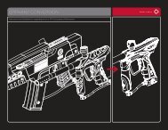
REINSTALLATION OF POPPET, POPPET-SPRING AND BOLT GUIDECAP-Place poppet assembly into the back of the bolt guide and gently pushforward. If installed properly the poppet assembly will be all the way forwardresting on the bolt guide internal face. Make sure the poppet spring is seatedstraight in the back of the poppetREMOVAL OF FOREGRIP ASSEMBLY- Using a 1/16” Allen key, loosen the Foregrip Retention Set Screws. They donot need to be fully removed, only loosened.-Using the 1/4” Allen key, screw the Bolt guide cap clockwise back into thebolt guide. Screw the Bolt guide cap all the way in, then turn out 1/2 turn.Further adjustment over a chronograph will be needed to achieve desiredvelocity.REINSTALLATION OF MAIN SPRING, BOLT AND BOLT GUIDE AS-SEMBLY-Slide main spring onto bolt, and then bolt onto bolt guide, so it is one assembly.You will notice, one end of the spring is smaller and will lock onto thebolt. Insert assembly into the back of body.- The Foregrip assembly will now slide down the front of the grip frame.INSTALLATION OF FOREGRIP-To reinstall the Foregrip Assembly on to the frame and body. Slide the Foregripassembly back onto the grip frame rail. Slide Foregrip assembly all theway up until it is back in place. Using the 1/16” Allen key, tighten the foregripretention set screws. Do not over tighten the set screws as they can becomedamaged easily.Note: On the top side of the bolt guide there is a small alignment hole at the rear of bolt guide.This must line up with the body alignment pin which sticks out the back of the body.-Holding the bolt assembly tight into the back of the body with one hand, re-install the rear framescrew and tighten using the 1/8” Allen key.Note: If not installed correctly, you might damage the Circuit Boards!WWW.INVERTPAINTBALL.COM15MINI MANUAL 08_v2.indd Sec1:15 9/8/08 3:53:02 PM
MINI MANUAL 08_v2.indd Sec1:17 9/8/08 3:53:27 PM
REMOVAL OF GRIP FRAME-Using a 1/8” Allen key, remove both grip frame screws turning counterclockwise.-Gently pull down frame from body.-When frame is back on, use the 1/8” Allen key and tighten the (2) grip framescrews clockwise.INSTALLATION OF GRIP FRAME-Inspect the air transfer tube o-ring and lightly grease. As you install the gripframe, make sure the solenoid wires do not get pinched and hold the triggerin to prevent the trigger activation magnet from getting damaged. Gentlypush grip frame back on and line up the air transfer tubes.REMOVAL, INSTALLATION AND CLEANING OF BALL DETENTS-Using a 5/64” Allen key, insert Allen key into detent cover and turn counterclockwise.-Clean the detents with a damp cloth and apply a small amount of grease tothe outer sides of the detents if sticking is a issue.-Installation is the reverse of the removal. Do not over tighten the Ball Detentcovers!18Note: Be careful not to lose any of the detent parts as they are small.MINI MANUAL 08_v2.indd Sec1:18 9/8/08 3:53:46 PM
14. MINI TROUBLESHOOTINGNote: If you are experiencing any problems and you are using any aftermarket parts, it is necessary to re-install the factory parts and re-testbefore attempting any troubleshooting, as non-factory aftermarket parts are not designed by <strong>Invert</strong> Paintball to work in the <strong>Mini</strong>, and theymay be the cause of the problems. Do not contact <strong>Invert</strong> Paintball until you have returned the <strong>Mini</strong> to factory stock condition and tested.Does not turn on Make sure you have a fresh battery. If you have tried several different batteries, check to make sure the batteryharness is plugged in to the board properly. If it is, unplug the battery fromthe harness for 5 minutes, then plug back in and try again.Doesn’t fire Make sure the marker is turned on. Check the LED light on the back of the foregrip. The LED should be rapidlyblinking green when a paintball is present.Doesn’t fire witheyes turned offMake sure you have a paintball in thechamber.The anti-chop eye system prevents the marker from firing unless a ballis present. Never put anything other than a paintball down the feed neckof the <strong>Mini</strong>.Trigger may need to be adjusted. Check the LED light on the back of the foregrip. While holding in the trigger,the LED should stay red in the background, and not be red when the triggeris released. If it is not that way, then the trigger may need to be adjusted. Seethe “Adjusting your trigger” section earlier in the manual.Trigger may need to be adjusted. Check the LED light on the back of the foregrip. While holding in the trigger,the LED should stay red in the background, and not be red when the triggeris released. If it is not that way, then the trigger may need to be adjusted. Seethe “Adjusting your trigger” section earlier in the manual.Solenoid may not be connectedproperly.Check to make sure the solenoid is connected properly to the sensor board.If it is, the solenoid may need to be reset.Solenoid may need to be reset. To reset the solenoid, with the eyes off, pull the trigger repeatedly until thesolenoid makes a loud clicking sound again with each trigger pull, but do notpull the trigger more than 10 times, as this can damage the solenoid. If after10 pulls the solenoid still doesn’t click, it may need to be serviced.WWW.INVERTPAINTBALL.COM21MINI MANUAL 08_v2.indd Sec1:21 9/8/08 3:53:52 PM
Shoots morethan once fromone trigger pullBattery may be low. Replace battery with a fresh Duracell or Energizer brand alkaline 9-volt.Trigger may need to be adjusted. Make sure the trigger has plenty of travel both before and after the activationpoint.Regulator leaksfrom bottom plugRegulator is slowto rechargeRegulatorpressure spikesBreaks paintin chamberAdjust over-pressurization relief valve. The plug on the underside of the regulator is an over-pressurization relief.If it is leaking, most likely the regulator is set to too high of a pressure andneeds to be lowered. If the regulator is set to 200 psi or less and the overpressurizationrelief is still leaking, it is possible to turn the plug cap just asmall amount in the clockwise direction, until the leak stops.Air tank is not screwed all the wayinto the <strong>Mini</strong>’s regulator ASA.If during rapid firing the first ball comes out of the barrel at full velocity andfollowing shots decrease substantially, watch the gauge on the <strong>Mini</strong> regulatorto see if the needle drops down significantly and is slow to come back tothe set pressure. This is typically the result of not screwing your air tank inenough. When screwing your air tank into the <strong>Mini</strong>’s regulator ASA, it is importantto not stop as soon as the marker pressurizes, but to continue turninguntil the air tank stops. It is also acceptable to install the air tank when it isempty, then have it filled by a professional while it is installed. This will ensurethat you get the maximum air flow from your air tank.Regulator adjusted too high. If the needle on the regulator’s gauge climbs well over 200 psi when attemptingto install the air tank, first remove the brass adjustment screw in the frontof the regulator and try again to install the air tank. If the needle reads 0,reinstall the adjustment screw and turn in until the needle reads 200 psi.Eyes are turned off. Only fire paintballs with the eyes on.Low quality or brittle paintballs. Do a paintball drop test. On a level and smooth, hard, outdoor surface, suchas concrete or asphalt pavement, drop ten paintballs one at a time from about5 feet high. Don’t toss them up or throw them at the ground, just drop themstraight down. If more than 3 paintballs out of 10 break, the paintballs are badand should not be used in the <strong>Mini</strong>. In the case of higher-end tournamentgradepaintballs, it may be possible to tune the <strong>Mini</strong> to successfully fire brittlepaintballs. Since all conditions are different, it is best to ask for help with thisfrom your local pro shop.WWW.INVERTPAINTBALL.COM23MINI MANUAL 08_v2.indd Sec1:23 9/8/08 3:53:53 PM
Breaks paintin chamberLoader pushing too hard. Try a different loader, such as the Empire Magna Drive Loader. If using a Haloseries or Empire Reloader B series loader, try installing an Empire MagnaClutch Upgrade Kit.Bolt or bolt guide o-rings may be worn. Air blowing past worn o-rings can easily break paintballs in the feed neck.Replace the bolt o-rings and the smaller 3 bolt guideO-rings and apply fresh grease.Bolt front seal may be missing. Make sure the bolt front seal is in place and has a light application of greaseto reduce friction.Check valve may be missing. Make sure the check valve is in place. Without the check valve, the forwardforce on the bolt is too great and can be too hard on the paintballs.Ball detents may be dirty or worn. Clean the ball detents. If necessary, apply a small amount of grease aroundthe outer surface to reduce friction inside the ball detent covers. Replace iftips are worn down.Regulator pressure maybe set too high.Lower regulator pressure.Cycles very slow Bolt or bolt guide o-ringsmay need grease.Clean off old grease from the bolt and bolt guide o-rings, as well as the boltfront seal, and apply fresh grease.Rate of Fire setting maybe adjusted too low.Raise Rate of Fire setting.Loader may not be feeding fast. Check your loader’s batteries or use a faster loader.InconsistentvelocityPressure may be set too low. Low pressures have difficulty supplying enough volume to maintain a constantvelocity. Do not lower your <strong>Mini</strong>’s regulator pressure below 180 psi.24MINI MANUAL 08_v2.indd Sec1:24 9/8/08 3:53:53 PM
InconsistentvelocityMarker may need to be greased. Clean old grease from the poppet, the bolt and bolt guide o-rings and applyfresh grease. Do not use too much, as it will prevent the moving parts fromcycling smoothly.Dwell may be set too low or too high. Reset the dwell setting to the factory default.Check valve may be missing. Make sure the check valve is in place.Battery may be low. Replace battery with a fresh Duracell or Energizer brand alkaline 9-volt.Poppet o-ring may be worn. Replace poppet o-ring and apply fresh grease.Regulator pressure maybe set too high.Lower regulator pressure.Velocity dropsoff when firingmultiple shotsScratcheson boltAir tank is not screwed all the wayinto the <strong>Mini</strong>’s regulator ASA.If during rapid firing the first ball comes out of the barrel at full velocity andfollowing shots decrease substantially, watch the gauge on the <strong>Mini</strong> regulatorto see if the needle drops down significantly and is slow to come back tothe set pressure. This is typically the result of not screwing your air tank inenough. When screwing your air tank into the <strong>Mini</strong>’s regulator ASA, it is importantto not stop as soon as the marker pressurizes, but to continue turninguntil the air tank stops. It is also acceptable to install the air tank when it isempty, then have it filled by a professional while it is installed. This will ensurethat you get the maximum air flow from your air tank.Spring may be damaged. This can cause negative performance. The main spring should be repaired bya trained technician or it can just be replaced.Leaks sometimeswhileshootingmultiple shotsPoppet may be sticking open. Clean the old grease from the poppet o-ring and apply fresh grease. If thatdoesn’t help, replace the poppet o-ring and apply fresh grease.WWW.INVERTPAINTBALL.COM25MINI MANUAL 08_v2.indd Sec1:25 9/8/08 3:53:54 PM
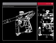
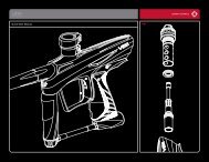
Leaks sometimeswhile shootingmultiple shotsBattery may be low. Replace battery with a fresh Duracell or Energizer brand alkaline 9-volt.Solenoid may be sticking open. If the solenoid is sticking open occasionally, the regulator pressure may beset too high. If the pressure is set to 200 psi or less, then the solenoid maybe filled with dirt and/or grease. See Maintenance section for instructions onhow to clean the solenoid.15. DIAGRAM AND PARTS LIST26PART # DESCRIPTION SKU #1 Body - Black 175052 Grip Frame - Black 175095 Foregrip Body - Black 175156 Foregrip Side Plate - Black 175197 Foregrip Retention Set Screw 175238 Main Board 175249 Battery Harness 1752510 Foregrip Screw 1752611 Sensor Board 1752712 Solenoid 1752819 Air Transfer Plate - Black 1757720 Air Transfer Plate Screw 1752921 Air Transfer Gasket 1753022 Check Valve 1753123 Bolt 1753224 Bolt Rubber Tip 1753325 Bolt/Bolt Guide Large Oring 1753426 Main Spring 1753527 Bolt Guide 17536MINI MANUAL 08_v2.indd Sec1:26 9/8/08 3:53:54 PM
15. DIAGRAM AND PARTS LIST....CONTINUEDPART # DESCRIPTION SKU #28 Bolt Guide Small (Front) Oring 1753731 Bolt Guide Cap 1758332 Bolt Guide Cap Oring 1753833 Poppet Assembly with Spring 1762835 Poppet Oring 1754036 Ball Detent (Complete) 1754140 Feed neck (Complete) - Silver Latch 1758543 Feed neck Clamp - Silver 1754646 Air Transfer Tube Male 1755147 Air Transfer Tube Male Top Oring 1755248 Air Transfer Tube Male Bottom Oring 1755349 Air Transfer Tube Female 1755450 Air Transfer Tube Female Oring 1755551 Regulator Mount 1755652 Regulator Mount Set Screw 1755753 Bottom-line Regulator (Complete) 1755862 Regulator Gauge 1759667 Trigger - Black 1756068 Trigger Pin 17562PART # DESCRIPTION SKU #70 Trigger Set Screw W/ Magnetic Top 1756471 Trigger Set Screw Long 1760272 Trigger Set Screw Short 1760374 Primary Body Retention Screw 1756575 Bolt Guide Alignment Screw 1756676 Grips - Urban Camo 1760577 Foregrip Rubber - Urban Camo 1760878 Grip Panel Screw 1756779 Poppet Spring 1762380 Poppet Seal 17629WWW.INVERTPAINTBALL.COM27MINI MANUAL 08_v2.indd Sec1:27 9/8/08 3:53:55 PM
16. WARRANTY INFORMATION- INVERT PAINTBALL LIMITED WARRANTY<strong>Invert</strong> Paintball warrants the replacement of any original part due to defect in materials and/or workmanship of this marker. This warranty will be in effect fortwelve (12) months for parts and twelve (12) months for labor following the original date of purchase for the original purchaser. Warranty is only retained if themarker is purchased as new; markers purchased used are not covered by warranty. Such warranty service will be provided only if the warranty registration cardincluded with this manual is filled in completely and a copy of the original receipt is on file at <strong>Invert</strong> Paintball. All other services will be duly charged by over thephone credit card and shipped UPS.<strong>Invert</strong> Paintball will replace, without charge, any original part that is determined by <strong>Invert</strong> Paintball to be defective under the terms of this warranty. However,shipping charges are not covered hereunder. Failure due to an accident, abuse, neglect, modification, loss, normal wear, operator error, maintenance by otherthan an authorized <strong>Invert</strong> Paintball dealer, or use of parts inconsistent with the use originally intended for the marker as sold, is not covered by this warranty. Thiswarranty does not apply to wearable parts such as o-rings, screws, poppet seal, ball detents, etc.There are no other warranties or guarantees, expressed or implied, made by <strong>Invert</strong> Paintball on this marker. The sole and exclusive liability of <strong>Invert</strong> Paintballand/or its authorized dealers, affiliates, or agents pursuant to this warranty will be for repair or replacement of the defective part; incidental or consequentialdamages are expressly excluded hereunder.Removing or disassembly of the original regulator voids all warranties, unless replaced with another MINI Bottom-line Regulator produced by <strong>Invert</strong> Paintball.If marker is to be sent in for repair, the marker must consist of all factory stock parts. Markers with aftermarket parts will not be warranted.For warranty parts, service or information contact:Paintball Solutionswww.paintballsolutions.com55 Howard Ave,Des Plaines, IL 600181-800-220-3222WWW.INVERTPAINTBALL.COM29MINI MANUAL 08_v2.indd Sec1:29 9/8/08 3:53:56 PM
WARRANTY REGISTRATIONSEND TO:PAINTBALL SOLUTIONS570 MANTUA BLVD.SEWELL, NJ 08080800-220-3222WWW.PAINTBALLSOLUTIONS.COMPURCHASE INFORMATIONPURCHASED FROM:CITY: STATE: ZIP:SERIAL:OWNER INFORMATIONYOUR NAME:CITY: STATE: ZIP:PHONE: EMAIL:30MINI MANUAL 08_v2.indd Sec1:30 9/8/08 3:53:56 PM
WWW.INVERTPAINTBALL.COM31MINI MANUAL 08_v2.indd Sec1:31 9/8/08 3:53:56 PM
MINI MANUAL 08_v2.indd Sec1:32 9/8/08 3:53:57 PM