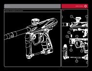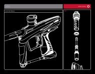
2010 DM Series Paintball Gun Manual - Dye Paintball
2010 DM Series Paintball Gun Manual - Dye Paintball
2010 DM Series Paintball Gun Manual - Dye Paintball
- No tags were found...

You also want an ePaper? Increase the reach of your titles
YUMPU automatically turns print PDFs into web optimized ePapers that Google loves.
2 0 1 0 D M S E R I E S O W N E R ’ s M A N U A Lw w w . d y e p a i n t b a l l . c o mTABLE OF CONTENTSImportant safety instructions and guidelines . . . . . . . . . . . . . . . . . . . . . . . . . page 02quick reference . . . . . . . . . . . . . . . . . . . . . . . . . . . . . . . . . . . . . . . . . . . . . . . . . . . . . . . . page 04board settings and functions. . . . . . . . . . . . . . . . . . . . . . . . . . . . . . . . . . . . . . . . . . page 06ON / OFF AIRPORT . . . . . . . . . . . . . . . . . . . . . . . . . . . . . . . . . . . . . . . . . . . . . . . . . . . . . . . . page 12Included with your <strong>2010</strong> <strong>DM</strong> <strong>Series</strong>- <strong>2010</strong> <strong>DM</strong> <strong>Series</strong> Marker- Allen tool set including 1 ⁄16”, 5 ⁄64”, 3 ⁄32”, 1 ⁄8”,5 ⁄32”, 3 ⁄16” and 1 ⁄4”- 1 ⁄4 oz. Slick Lube- Parts Kit- Barrel Sock- Owner’s <strong>Manual</strong>- Warranty CardADditional Recommended tools- 5 ⁄16” Allen wrench- Canned Air- 7 ⁄16” Socket Wrench- Cotton SwabsCLAMPING FEEDNECK . . . . . . . . . . . . . . . . . . . . . . . . . . . . . . . . . . . . . . . . . . . . . . . . . . . . . page 12Trigger adjustment . . . . . . . . . . . . . . . . . . . . . . . . . . . . . . . . . . . . . . . . . . . . . . . . . . . . page 14fuse bolt . . . . . . . . . . . . . . . . . . . . . . . . . . . . . . . . . . . . . . . . . . . . . . . . . . . . . . . . . . . . . . page 16low pressure regulator (LPR) . . . . . . . . . . . . . . . . . . . . . . . . . . . . . . . . . . . . . . . . . . page 20Hyper3 . . . . . . . . . . . . . . . . . . . . . . . . . . . . . . . . . . . . . . . . . . . . . . . . . . . . . . . . . . . . . . . . . page 24ANti chop eyes/ ball detents . . . . . . . . . . . . . . . . . . . . . . . . . . . . . . . . . . . . . . . . . . . page 26Trouble Shooting Guide . . . . . . . . . . . . . . . . . . . . . . . . . . . . . . . . . . . . . . . . . . . . . . . . page 28Exploded view . . . . . . . . . . . . . . . . . . . . . . . . . . . . . . . . . . . . . . . . . . . . . . . . . . . . . . . . . . page 32Warranty information . . . . . . . . . . . . . . . . . . . . . . . . . . . . . . . . . . . . . . . . . . . . . . . . . page 33w w w . d y e p a i n t b a l l . c o m1
W A R NI N GIMPORTANT SAFETY INSTRUCTIONS AND GUIDELINESW A R N I N GIMPORTANT SAFETY INSTRUCTIONS AND GUIDELINES• The <strong>2010</strong> <strong>DM</strong> <strong>Series</strong> marker is not a toy. Misuse may cause seriousinjury or death.• Please read, understand and follow the directions in the <strong>2010</strong><strong>DM</strong> <strong>Series</strong> owner’s manual.• Eye protection that is designed specifically for paintball and meetsASTM/CE standards must be worn by user and persons within range.• Recommend 18 years or older to purchase. Person under 18 musthave adult supervision.• Always treat the <strong>2010</strong> <strong>DM</strong> <strong>Series</strong> marker as if it were loaded and ableto fire.• Only use compressed air or nitrogen gas in the <strong>2010</strong> <strong>DM</strong> <strong>Series</strong>marker. DO NOT USE CO 2 .• Do not exceed 850 psi input pressure.• Ensure all air lines and fittings are tightened and secured beforegassing up the <strong>2010</strong> <strong>DM</strong> <strong>Series</strong>.• Always chronograph the <strong>2010</strong> <strong>DM</strong> <strong>Series</strong> marker before playingpaintball.2w w w . d y e p a i n t b a l l . c o m• Never shoot the <strong>2010</strong> <strong>DM</strong> <strong>Series</strong> marker at velocities in excess of 300feet per second, or at velocities greater than local or national laws allow.• Never look into the barrel or breech area of the <strong>2010</strong> <strong>DM</strong> <strong>Series</strong> whenthe marker is switched on and able to fire.• Always fit a barrel blocking device to your <strong>2010</strong> <strong>DM</strong> <strong>Series</strong> when notin use on the field of play.• The owner’s manual should always accompany the product forreference or in the event of resale and new ownership.• Do not point the <strong>2010</strong> <strong>DM</strong> <strong>Series</strong> marker at anything that you do notintend to shoot.• Do not shoot at people, animals, houses, cars or anything not relatedto the sport of paintball.• Do not fire the <strong>2010</strong> <strong>DM</strong> <strong>Series</strong> without the Fuse bolt screwed incompletely.• If you read these instructions and do not fully understand them orare unsure of your ability to make necessary adjustments properly,call DYE or your local pro shop for help.w w w . d y e p a i n t b a l l . c o m3
QUICK REFERENCEUSING YOUR MARKERQUICK REFERENCEUSING YOUR MARKERAir SupplyThe <strong>2010</strong> <strong>DM</strong> <strong>Series</strong> should be operated using air/nitrogen gas only. This air needs to besupplied to the Hyper3 in-line regulator at a regulated pressure of no more than 850 psi. TheHyper3 in-line regulator comes factory preset at 145psi.Gassing Up Your <strong>2010</strong> <strong>DM</strong> <strong>Series</strong>Screw in your air system to the ON/OFF airport and turn the knob of the airport clockwise, allthe way in.Turning On Your <strong>2010</strong> <strong>DM</strong> <strong>Series</strong>The <strong>2010</strong> <strong>DM</strong> <strong>Series</strong>’s power is controlled by two buttons. The top button turns the markeron and off, while the bottom button turns the eyes on and off. Hold the power button for 3seconds to turn the marker on. The LED in the grip will illuminate during the boot sequence.NOTE: If the eye is not working properly, try replacing the battery.Blue::- Boot sequenceRed:- Breech is clear, no ball (eyes on)Green: - Ball in breech, ready to fire (eyes on)Blinking Red: - Eyes are offBlinking Green: - Eye failure (see page 26)Blinking Blue: - Indicates a low battery, battery should be changedas soon as possibleLPRThe LPR is pre-set from the factory at approximately 75-80 psi and should need no adjustmentout of the box. If fine tuning adjustment is desired or needed, you must be sure that you areadjusting the LPR correctly. See page 23 for detailed instructions. If the LPR is improperlyadjusted, you could dramatically hinder the <strong>2010</strong> <strong>DM</strong> <strong>Series</strong>’s performance orprevent the marker from functioning at all.4w w w . d y e p a i n t b a l l . c o mNOTE: Turning the adjustment screw clockwise, or in, will lower the LPR’s output pressure.Turning the adjustment screw counterclockwise, or out, will raise the LPR’s output pressure.HopperTo get the best performance out of your <strong>2010</strong> <strong>DM</strong> <strong>Series</strong>, it is recommended that you use amotorized loader. Preferably, the Rotor Loader.Adjusting VelocityThe velocity is adjusted through the Hyper3 in-line regulator. The Hyper3 in-line is preset fromthe factory at approximately 145 psi. This pressure setting should have the marker shooting atabout 285fps. Your paint-to-barrel fit will also have a noticeable affect on your velocity. Makesure that the paintball fits into the barrel loosely but does not drop through.NOTE: For the Hyper3, turning the adjustment screw clockwise, or in, will lower the outputpressure, decreasing the velocity. Turning the adjustment screw counterclockwise, or out, willraise the output pressure, increasing the velocity.CHANGING THE BATTERYThe battery is housed on the right side of the grip frame. To access the battery, remove the threescrews holding the right side grip panel down. Use a 3 ⁄32” Allen wrench. Carefully lift the batteryout of the frame. When inserting a new battery notice the + and - marks on the board. Thepositive lead of the 9V battery goes to the left and the negative lead to the right. Inserting thebattery backwards does not damage the board but it will not function.• A low battery will not be able to power both the ACE eye and the triggerswitch, causing ACE eye failure.• If the battery is low, it may not be able to power the solenoid correctly.This will affect the <strong>2010</strong> <strong>DM</strong> <strong>Series</strong>’s velocity, causing it to become inconsistentand/or low.w w w . d y e p a i n t b a l l . c o m5
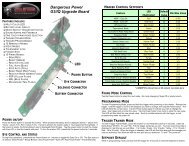
<strong>2010</strong> <strong>DM</strong> SERIES BOARDSettings and Functions<strong>2010</strong> <strong>DM</strong> <strong>Series</strong> BOARDSettings and FunctionsTurning the <strong>2010</strong> <strong>DM</strong> <strong>Series</strong> ON and OFFTo turn on the <strong>2010</strong> <strong>DM</strong> <strong>Series</strong>, press and hold the powerbutton for 3 seconds (see figure 1) until the LED’s turn blue.The blue light indicates board boot up. After the boot upsequence, the LED’s will turn either RED (no ball) or GREEN(ball ready to fire). To turn the <strong>2010</strong> <strong>DM</strong> <strong>Series</strong> off, press andhold the power button until the LED’s turn off.NOTE: The <strong>2010</strong> <strong>DM</strong> <strong>Series</strong> automatically switches off after10 minutes of non-use.When you turn on the marker in normal operation mode with the power button, the light colorsmean the following:Blue: - Boot sequenceRed: - Breech is clear, no ball detected inside the <strong>2010</strong> <strong>DM</strong> <strong>Series</strong> (eye is on)Green: - Ball in breech, ready to fire (eye on)Blinking Red: - Eye is turned offBlinking Green: - Eye failure, eye is blocked or dirty (see <strong>2010</strong> <strong>DM</strong> <strong>Series</strong> Eye, page 26)Blinking Blue: - Indicates a low battery, battery should be changed as soon as possibleFIGURE 1Firing the <strong>2010</strong> <strong>DM</strong> <strong>Series</strong>As soon as the marker is turned on and the LED’s turn fromblue to either red or green, the <strong>2010</strong> <strong>DM</strong> <strong>Series</strong> is ready tofire. If there is no ball and the LED’s are RED, you need tohold the trigger for 1 second to force the <strong>2010</strong> <strong>DM</strong> <strong>Series</strong>to fire once. If there is a paintball inside the breech and theLED is green, just press the trigger to fire the marker.To turn the eyes off, press and hold the lower button until the light begins flashing red.To turn the eyes back on, hold the lower button until the LED turns either red or green.NOTE: With the eye off the <strong>2010</strong> <strong>DM</strong> <strong>Series</strong> will shoot the rate of fire value set inConfiguration Mode.LED Light IndicatorBLUE RED GREENNOTE: The eye is always activatedwhen you turn the marker on.6The <strong>2010</strong> <strong>DM</strong> <strong>Series</strong> uses two super bright LED’s mountedon the circuit board inside the grip frame. These two lightsare used to provide information to the user about the <strong>2010</strong><strong>DM</strong> <strong>Series</strong>. They will always show the same information andit does not matter which LED you look at. One is mountedbehind the <strong>2010</strong> <strong>DM</strong> <strong>Series</strong> logo on the left side of the grippanels. The other one can be seen by looking at the top leftside of the grip frame while holding the <strong>2010</strong> <strong>DM</strong> <strong>Series</strong> inthe position you would while playing a game.w w w . d y e p a i n t b a l l . c o mWhen servicing your marker:• Make sure a barrel sock is fitted to the <strong>2010</strong> <strong>DM</strong> <strong>Series</strong>.• Make sure your hopper is removed from the <strong>2010</strong> <strong>DM</strong> <strong>Series</strong>.• Make sure there are no paintballs in the breech of the <strong>2010</strong> <strong>DM</strong> <strong>Series</strong>.• Always remove the first stage regulator and relieve all residual gas pressure from the<strong>2010</strong> <strong>DM</strong> <strong>Series</strong> before disassembly.• The <strong>2010</strong> <strong>DM</strong> <strong>Series</strong> can hold a small residual charge of gas, typically 2 shots, with thefirst stage regulator removed. Always discharge the marker in a safe direction torelieve this residual gas pressure.w w w . d y e p a i n t b a l l . c o m7
<strong>2010</strong> <strong>DM</strong> <strong>Series</strong> BOARDSettings and Functions<strong>2010</strong> <strong>DM</strong> <strong>Series</strong> BOARDSettings and FunctionsFIGURE 1BOARD SETTINGS AND CONFIGURATION MODEThere are five settings you can alter on the <strong>2010</strong> <strong>DM</strong> <strong>Series</strong>board with the DIP switches inside the grip frame (see figure 1):ABSanti Bolt Stick.Trigger Sensitivity This setting adjusts the delaybetween two trigger pulls.Dwellthis is the time the solenoid isactivated for.Rate Of Fire Rate Of Fire when the eye isdeactivated.Firing Mode This is the firing mode the <strong>2010</strong>dm <strong>Series</strong> uses.There are two DIP switches mounted on the board of the<strong>2010</strong> <strong>DM</strong> <strong>Series</strong> (See figure 1). The first one is used forthe ABS setting and the second one is used to access theconfiguration mode which changes the other four settings.Configuration Mode - The following settings can only bemodified in configuration mode. To activate the configurationmode, turn your marker off and set DIP switch 2 to the ONposition. Next, turn your marker on. The LED’s cycle throughall colors for one second to indicate that you have enteredthe configuration mode.NormalModeConfigurationModeTo cycle through different settings, pull and release the trigger. Configuration mode has4 settings that can be changed.Green - Trigger Sensitivity Values 1 - 20 (factory default 3)trigger sensitivity is the amount of time that the trigger has to bereleased before the next trigger pull is allowed. In some situationswith too low of a value, the <strong>2010</strong> <strong>DM</strong> <strong>Series</strong> can register more triggerpulls than what was actually pulled. This can cause the <strong>2010</strong> <strong>DM</strong><strong>Series</strong> to shoot full auto, even in semi-automatic mode. To fix this,adjust trigger sensitivity setting higher.Anti Bolt Stick - When ABS is activated, the dwell is increased after15 seconds of non-use for the next shot fired. This helps to preventbolt-stick, but may result in higher velocity for the first shot.8ABS ON(default)ABS OFF• The <strong>2010</strong> <strong>DM</strong> <strong>Series</strong> is not water resistant. Excess moisture can cause damage toelectronic parts.• Keep the board and all electrical components clean of dirt, paint and moisture.• To clean the board, use canned air. If a more aggressive cleaning method is needed,lightly scrub the components with a soft, dry brush. Heavy scrubbing will damagethe board.w w w . d y e p a i n t b a l l . c o mRed - Dwell Values 1 - 30 (factory default 18)dwell is the amount of time that the solenoid will be activated.Follow these steps for the best way to set your dwell:• Remove loader and any paintballs from the <strong>2010</strong> <strong>DM</strong> <strong>Series</strong> marker.• With the dwell set at 10, start increasing the value until the markerbegins to fire.• When you reach the setting where the marker begins to fire, getsome paint and a loader and go to a chronograph.• Increase the dwell until you see no increase in the velocity.this is the optimal dwell setting to be used.w w w . d y e p a i n t b a l l . c o m9
<strong>2010</strong> <strong>DM</strong> <strong>Series</strong> BOARDSettings and Functions<strong>2010</strong> <strong>DM</strong> <strong>Series</strong> BOARDBATTERYBlue - Rate Of Fire (ROF)1 9.80 BPS2 9.90 BPS3 10.0 BPS4 10.10 BPS5 10.20 BPS6 10.30 BPS7 10.41 BPS8 10.52 BPS9 10.63 BPSValues 1 - 45 (factory default 12.5 bps)The ROF setting is used to set the maximum rate of fire of the <strong>2010</strong>dm <strong>Series</strong>. The values do not correspond directly to a certain Ballsper Second (BPS) value. You will need to use the table below tolocate your desired maximum ROF setting.the factory setting is 20 (12.5 bps).10 10.75 BPS11 10.86 BPS12 10.98 BPS13 11.11 BPS14 11.62 BPS15 11.76 BPS16 11.90 BPS17 12.04 BPS18 12.19 BPS19 12.34 BPS20 12.50 BPS21 12.65 BPS22 12.82 BPS23 12.98 BPS24 13.15 BPS25 13.33 BPS26 13.51 BPS27 13.69 BPS28 13.88 BPS29 14.08 BPS30 14.28 BPS31 14.49 BPS32 14.70 BPS33 14.92 BPS34 15.15 BPS35 15.38 BPS36 15.62 BPS37 15.87 BPS38 16.12 BPS39 16.39 BPS40 16.66 BPS41 20.0 BPS42 22.22 BPS43 25.0 BPS44 28.57 BPS45 33.33 BPSYellow - Firing Mode Values 1 - 4 (default 1)this setting changes the firing mode of the <strong>2010</strong> <strong>DM</strong> <strong>Series</strong>. Defaultis semiautomatic. In the semiautomatic mode, one trigger pullshoots out one paintball. The PSP mode and the Millenniummode follow the rules of the paintball tournament series.Value 1 - Semiautomatic ModeValue 2 - Millennium ModeValue 3 - PSP ModeValue 4 - Full Auto10NOTE: You cannot turn your marker off with the power button when the markeris in configuration mode. You must first set DIP switch 2 to the OFF position.w w w . d y e p a i n t b a l l . c o mTO CHANGE A VALUE OF A SETTING1. While in the configuration mode, choose the color you wish to change by pulling the trigger.2. When the LED indicates the color you wish to change, pull and hold the trigger until the LEDstarts to flash.3. The LED will flash as many times as the previous setting was and it will then turn off. Now pullthe trigger as many times as you wish the new setting to be.4. When done, the LED will cycle through all the colors again to indicate setting was saved andturn back to green. You can now change another setting or quit the configuration mode.5. To exit configuration mode, set DIP 2 to the off position.BATTERYStandard 9V batteries will last for about 40,000 shots. Please beaware that there are substantial differences in performance betweendifferent brands of batteries. Use of high quality alkaline or lithiumion batteries is recommended for maximum battery life. If you plannot to use your marker for a long period of time (a month), it isrecommended that you remove the battery from the marker.An intermittent blinking blue light indicates a low battery. A lowbattery can cause the marker to malfunction.• A low battery will not be able to power both the ACE eye and the trigger switch,causing ACE eye failure.• If the battery is low, it may not be able to power the solenoid correctly. This willaffect the <strong>2010</strong> <strong>DM</strong> <strong>Series</strong>’s velocity, causing it to become inconsistent and/or low.w w w . d y e p a i n t b a l l . c o m11
ON/OFF AIRPORT - FEEDNECKULTRALITE FRAMEon/off airportThe <strong>2010</strong> <strong>DM</strong> <strong>Series</strong> comes equipped with an On/OffAirport attached to the bottom of the frame. To turn onthe gas supply, twist the ON/OFF knob clockwise, allthe way in. To turn off the gas supply, twist the ON/OFFknob counterclockwise, all the way out. As you turn theknob out, the residual gas between the Hyper3 and theON/OFF airport is vented. To remove the airport fromthe UL frame see page 13.REMOVING ULTRALITE FRAME FROM THE <strong>2010</strong> <strong>DM</strong> <strong>Series</strong>If there is ever need to remove the Ultralite frame from the <strong>2010</strong> <strong>DM</strong> <strong>Series</strong> make sure to followthese steps.• Remove three grip panel screws with a 3 ⁄32” Allen wrench from the right side of Ultralite frame.• Disconnect the solenoid wire and the eye wire from their sockets by gently pulling them out.• Using a 3 ⁄32” Allen wrench, turn the front frame screw counterclockwise one full turn.• Finally, turn out the back frame screw and slide the frame back and down until it comes offthe <strong>2010</strong> <strong>DM</strong> <strong>Series</strong>.To connect the frame follow above steps in reverse order.INTEGRATED LOCKING DOVETAIL FEATURECam lever feed neckThe Cam lever feed neck is adjustable to fit anystandard loader. To adjust the cam locking system turnthe thumb adjustment knob clockwise to tighten, orcounterclockwise to loosen. Press the cam lever downagainst the feed collar to secure the loader in the feedneck. To loosen the locking system and remove theloader, lift the cam lever away from the feed collar.Take care not to over tighten the cam locking system.The cam lever should not be difficult to lower into thelocked position.The Ultralite frame comes equipped with an integrated locking dovetail. There is a horizontallocking screw located on the bottom right side of the Ultralite frame. It can be accessed with a1 ⁄8” Allen wrench through a hole in the grip panel. To unlock a part attached to the dovetail of theframe, turn the locking screw counterclockwise one full turn and slide part off the rail. To attach apart to the rail, slide the part on and turn the locking screw clockwise until part is firmly locked inplace.NOTE: Be sure that the frame and trigger assembly are kept clean. If there is excess dirt orpaint build up around the trigger, the trigger will no longer move freely. In addition, paint anddirt can cause the microswitch to not function properly or fail. Be sure you do not pinch thewires between the frame and the body when reattaching the frame and body.12NOTE: Even with the air supply removed the marker may havegas inside. Be sure to vent this gas. Make sure there are no paintballsin the breech and dry fire the marker in a safe direction.w w w . d y e p a i n t b a l l . c o mw w w . d y e p a i n t b a l l . c o m13
TRIGGER ADJUSTMENTTRIGGER ADJUSTMENTAdjusting your triggerThe trigger’s forward and over travel, spring tension, andreach are fully adjustable so that you can fine-tune thetrigger to your exact liking. You do not need to removethe frame or grip from the gun in order to adjust thetrigger pull.There are two adjustment screws located on the rightside of the Ultralite frame and one adjustment screwbehind the trigger. The two screws on the side of theframe adjust the travel of the trigger.The one located behind the trigger is used to change thetension of the trigger spring.To adjust trigger travel (SEE FIGURE 1)Use a 5 ⁄64” Allen wrench to make the desired adjustments.• The screw toward the front of the trigger (1) controls the forward travel. Screwing it in willshorten the trigger’s length of pull.Note: If this screw is adjusted too far, the switch will be held down at all times and the markerwill not fire.• The screw toward the rear of the trigger (2) controls the over travel. By turning this screw youcan adjust how far the trigger will travel after it reaches the firing point.Note: If this screw is adjusted too far, the trigger will not be allowed to travel far enough todepress the switch and fire the marker.FIGURE 1 FIGURE 21234ULTRALITE REACH TRIGGERThe <strong>2010</strong> <strong>DM</strong> <strong>Series</strong> has a new external reachadjustment for the Ultralite trigger.this adjustment changes the angle that thetrigger sits without the need to take off thegripframe or Sticky3 Grip.TO ADJUST TRIGGER REACH(SEE FIGURES 1 AND 2)To adjust, simply loosen the two 6-32 screws(4) using a 1/16” Allen wrench. You do nothave to remove the screws from the trigger.Now the front of the trigger (shown ingreen) should rotate freely while the back ofthe trigger (shown in blue) remains relativelystationary. When the desired reach angle hasbeen achieved, tighten the two 6-32 screwssnugly. Be careful not to over tighten andstrip the Allen wrench or screws.Note: The spring tension adjustment (outlined on page 14) should be set while the trigger’sreach is situated in either the rear position or the loose position so the spring tension adjustscrew can be externally accessed.To adjust spring tension (SEE FIGURE 1)• Use a 5 ⁄64” Allen wrench to make the desired adjustment. The adjustment is made bypushing the Allen wrench through a hole in the trigger (3).• To make the trigger pull stiffer, turn the Allen wrench clockwise or in.• To make the trigger pull lighter, turn the Allen wrench counterclockwise or out.14w w w . d y e p a i n t b a l l . c o m• Be sure the trigger is not adjusted to the point where it is too sensitive and maycause accidental discharge of the marker.• Removing the trigger spring will cause premature wear on the microswitch,resulting in failure.w w w . d y e p a i n t b a l l . c o m15
FUSE BOLTAssembly and MaintenanceFUSE BOLTAssembly and Maintenance1FUSE BOLT OPERATIONTo achieve top performance fromyour <strong>2010</strong> <strong>DM</strong> <strong>Series</strong>, it is important tounderstand the basic operation of the<strong>2010</strong> <strong>DM</strong> <strong>Series</strong>’s patented FUSE boltsystem.Forward PositionThis design consists of three sleevesthreaded together to capture the onlymoving part of the system, the bolt.The FUSE Bolt has five components:1 Cylinder2 Bolt Sail3 boltBACK Position4 Top Hat5 Rear CapAir is supplied to the bolt at two points. A high-pressure supply of air is routed to the back of thebolt into the supply chamber. This air source is responsible for propelling the ball. Low-pressureair is supplied from the LPR to the solenoid. From the solenoid, the air is routed through twosmall holes to the section of the bolt referred to as the cylinder.When the <strong>2010</strong> <strong>DM</strong> <strong>Series</strong> is aired up, air is transferred by the solenoid to the front of the cylinder.This air pushes against the bolt sail and the bolt is held in the back position.1623w w w . d y e p a i n t b a l l . c o m45When the bolt is held back, the 014 O-ring inthe top hat seals around the bolt and containsthe air in the supply chamber. When themarker is fired, the microswitch is pressed,telling the solenoid to switch the flow of airfrom the front of the cylinder to the rear ofthe cylinder. Air that enters the rear of thecylinder will push on the bolt sail, movingthe bolt forward. The air in the front of thecylinder is vented.As the bolt moves forward, the tapered stempasses through the top hat. Once the boltstem can no longer seal against the 014O-ring, the air contained in the supply chamberis released. The air passes through the venturiports in the bolt and out the front of the bolt to propel the ball. When the bolt is in the forwardposition, the inside bolt stem O-ring prevents the flow of air from continuously flowing through themarker when the bolt is forward. This helps the marker shoot much more efficiently.Note: Low or erratic velocity may be due to a low battery not supplyingample electrical current to the solenoid. In this case, change the battery.When servicing your marker:• Make sure your hopper is removed from the <strong>2010</strong> <strong>DM</strong> <strong>Series</strong>.• Make sure there are no paintballs in the breach of the <strong>2010</strong> <strong>DM</strong> <strong>Series</strong>.• Always remove the air supply and relieve all gas pressure in the <strong>2010</strong> <strong>DM</strong> <strong>Series</strong> beforedisassembly.• When using the marker in temperatures below 50° Fahrenheit it may be necessary tolube the FUSE bolt more frequently.w w w . d y e p a i n t b a l l . c o m17
FUSE BOLTAssembly and MaintenanceFUSE BOLTAssembly and MaintenanceBolt MaintenanceRegular <strong>2010</strong> <strong>DM</strong> <strong>Series</strong> Fuse bolt maintenance is vital to the performance of the <strong>2010</strong> <strong>DM</strong><strong>Series</strong>. If the Fuse bolt is not kept well-greased and the O-rings in good shape, the performanceof the <strong>2010</strong> <strong>DM</strong> <strong>Series</strong> will be greatly hindered.To remove the bolt, you will need a 1 ⁄4“ Allen wrench. Unscrew the bolt from the rear of themarker. It only takes one and one half revolutions to unscrew the bolt so that it can be pulledout. After the bolt has been cleaned and greased and is ready to be inserted into the body, besure all bolt sleeve components are screwed together snugly. Slowly push the bolt into the body.Take care not to cut or nick the O-rings as they pass the threads.Grease the <strong>2010</strong> <strong>DM</strong> <strong>Series</strong> FUSE bolt every 10-15 thousand shots AND CHECKCONDITION OF O-RINGS. BE SURE THE FUSE BOLT CAN MOVE BACK AND FORTH WITHOUTEXCESSIVE FORCE.FUSE Bolt O-ring list (COLOR CODED)1 Bolt tip (014 BN70) 6 Top hat small internal (014 BN70)2 Bolt sail (015 BN70) 7 Outer sleeve (020 BN70)3 Bolt stem (011 BN70) 8 Sail bumper (111 BN70)4 Cylinder internal (017 BN70)5 Top hat large internal (017 BN70)77 777Before installing the bolt into the marker, be sure all bolt sleevecomponents are screwed together snugly.5 6If you do not grease the bolt, you will run the risk of damaging O-rings. This will create excessivefriction and drag on the bolt, ultimately resulting in breaking the bolt. When greasing the <strong>2010</strong><strong>DM</strong> <strong>Series</strong> Fuse bolt, pay special attention to all O-rings that are on the bolt and that ride ona surface of the bolt. The first seven O-rings listed on the following page should be generouslygreased during maintenance.41883 318w w w . d y e p a i n t b a l l . c o m2w w w . d y e p a i n t b a l l . c o m19
LPR (Low Pressure Regulator)Adjustments and MaintenanceLPR (Low Pressure Regulator)Adjustments and MaintenanceLpr assembly, cleaning, testing andchanging sealsThe Low-Pressure Regulator (LPR)is located at the back of the <strong>2010</strong> <strong>DM</strong><strong>Series</strong> under the bolt (seepage 23). The function of the LPR is tolower the air pressuresupplied to the marker by the in-linebefore itreaches the solenoid. This pressure isused tomove the bolt forward and back. Thefactory setting is 75 PSI. You canfine tune your <strong>2010</strong> <strong>DM</strong> <strong>Series</strong> toits minimum cycle pressure. Thiswill reduce the amount of force ofthe bolt hitting the ball (reducingball breaks) and help withefficiency. Too low of pressure willcause the bolt to not fully cycle, movesluggishly or not at all. If you experience dramaticshoot down during rapid fire, the LPR may be adjustedtoo low. Too high of pressure will cause excess kick, potentiallyincrease ball breakage, and cause fatigue on the bolt components.The LPR has five components and six seals1 Piston O-ring (012 BN70) 6 Body internal O-ring (007 UR90)2 Piston 7 Seat (mounted in the seat retainer)3 Shim stack 8 Seat retainer O-ring (010 BN70)4 LPR Body 9 Seat retainer (functions as an adjustment screw also)5 Body O-rings (2 pcs, 012 BN70)The only user-serviceable part in the LPR is the seat retainer (see page 22). This seal needs to bechanged in the unlikely case the LPR is allowing gas through the regulator, increasing pressuresent to the solenoid.1235456 798It is important to keep the seat and piston face clean of all dirt and debris. Clean the seat andpiston face and grease the retainer O-ring every six months or 60,000 shots.When servicing your marker:• Make sure your hopper is removed from the <strong>2010</strong> <strong>DM</strong> <strong>Series</strong>.• Make sure there are no paintballs in the breach of the <strong>2010</strong> <strong>DM</strong> <strong>Series</strong>.• Always remove the air supply and relieve all gas pressure in the <strong>2010</strong> <strong>DM</strong> <strong>Series</strong> beforedisassembly.• It is recommended for the user to remove the LPR from the body and disassemble it.20w w w . d y e p a i n t b a l l . c o mw w w . d y e p a i n t b a l l . c o m21
LPR (Low Pressure Regulator)Adjustments and MaintenanceLPR (Low Pressure Regulator)Adjustments and MaintenanceChanging the seat retaineR1 Unscrew the LPR cap from theback of the <strong>2010</strong> <strong>DM</strong> <strong>Series</strong> with a 1 ⁄4”Allen wrench.2 Unscrew and remove the brassLPR seat assembly using a 3 ⁄16” Allenwrench.3 Use a dental pick or sharp objectto remove the old seat from theretainer and replace it with a newone. Use a flat object to press it intoplace.4 Lube the #010 O-ring and screwthe seat retainer assembly back intothe LPR assembly.5 Screw the LPR back cover backinto the <strong>2010</strong> <strong>DM</strong> <strong>Series</strong>.If the user needs to replace the whole LPR assembly, follow these instructions:1 Take the frame off of the marker (see page 13 for removal instructions).2 Unscrew the LPR set screw from the underside of the body using a 5 ⁄64” Allen wrench.3 Unscrew the LPR cap from the back of the <strong>2010</strong> <strong>DM</strong> <strong>Series</strong> with a 1 ⁄4” Allen wrench.4 Pull out the LPR, making sure that the piston is not left in the <strong>2010</strong> <strong>DM</strong> <strong>Series</strong> body.5 Insert a new LPR Assembly.6 Tighten LPR screw lightly, being sure to align it with the keyway cut on the LPR body.7 Screw the LPR back cover into the <strong>2010</strong> <strong>DM</strong> <strong>Series</strong> body.8 Replace frame (see page 13 for replacement instructions).The LPR pressure can be setquite accurately even withoutan LPR test tool. While the<strong>2010</strong> <strong>DM</strong> <strong>Series</strong> is degassed,screw the brass seat retainerclockwise with a 3 ⁄16” Allenwrench until slight resistanceis felt.Applying excessive torque tothe seat retainer will damagethe LPR seat.The LPR is now set toapproximately 10 psi. Nowturning out the retainer 180degrees counterclockwisewill increase the pressureapproximately 5 psi.For example, turning theretainer 3 to 5 complete turnsout will set the pressure toapproximately 65-75 psi. Usea chronograph to fine-tune thepressure to where the <strong>2010</strong> <strong>DM</strong><strong>Series</strong> is consistent.22w w w . d y e p a i n t b a l l . c o mw w w . d y e p a i n t b a l l . c o m23
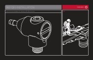
Hyper3 IN-LINE REGULATORAdjustments and MaintenanceHyper3 IN-LINE REGULATORAdjustments and MaintenanceBOTTOM CAPSwivel010 BN 70 007 UR 90 013 BN 70011 BN 70SEAT retainerRegulator seatBODYTop CapusageCarefully connect the ¼” macroline from the airport fitting into the Hyper3 elbow fitting.The macroline should be cut straight with a sharp knife to prevent leaks.ADJUSTMENTSThe Hyper3 regulator is adjusted in the same manner as the LPR (outlined on page 23). With theseat retainer screwed completely in the Hyper3 will be set to 0 psi. Each turn counterclockwisewill increase the pressure by approximately 25 psi. The stock setting is 145 psi, which should resultin the <strong>2010</strong> <strong>DM</strong> <strong>Series</strong> shooting velocities of about 285fps.Hyper3 REGULATOR DIS-ASSEMBLY INSTRUCTIONSThe rubber sleeve on the outside of the Hyper3 does not need to be removed to disassemblethe seat assembly, but may make the process easier. Begin by inserting a 3 ⁄16” Allen wrenchinto the topcap and a 5 ⁄16” Allen wrench into the bottom cap. Unscrew the bottom cap fromthe Hyper3. If the topcap begins to unscrew, try tightening the regulator back together andunscrewing again. Sometimes it is necessary to use a vice to hold the Hyper3 body to removethe bottom cap. The brass seat retainer and swivel can now be removed from the regulator. If theswivel is stuck, the elbow fitting may need to be removed.To change the seat, remove the seat retainer from the regulator body. Use a dental pick or sharpobject to remove the old seat from the retainer and replace it with a new one. Use a flat object topress it into place.Any further disassembly should be performed by a trained tech. If you have any questions pleasecall the DYE tech line.ReassemblyGrease the #010 O-ring on the seat retainer and the two #013 O-rings on the Hyper3 body.Insert the seat retainer being careful to not screw it in too tightly. Slide the swivel gently backonto the body and screw on the bottom cap. If the elbow fitting was removed, use thread sealantand snugly screw it back into the swivel making sure that the swivel can rotate freely.MaintenanceThe Hyper3 regulator requires little maintenance from regular use. The seat should be replacedevery 6 months or 60,000 shots. Shooting the <strong>2010</strong> <strong>DM</strong> <strong>Series</strong> a few times between each smalladjustment to the regulator, will lengthen the life of the seat. Also, O-rings and the seat may wearrapidly if excessive dirt or sand is allowed into the regulator, so the Hyper3 should be kept clean.24w w w . d y e p a i n t b a l l . c o m• The Hyper3 can hold a small residual charge of gas, typically 1 shot.Always discharge the marker in a safe direction to relieve this residual gas pressure.• Improper stacking of shims will cause failure of the regulator and possible damageto the <strong>2010</strong> <strong>DM</strong> <strong>Series</strong>.• Excessive dirt and debris can affect the Hyper3’s performance and increase theneed for service.w w w . d y e p a i n t b a l l . c o m25
ANTI CHOP EYEs/ BALL DETENTSMAINTENANCE AND CHANGINGANTI CHOP EYEs/ BALL DETENTSMAINTENANCE AND CHANGINGAnti chop eyesThe Anti Chop Eye (ACE) system will prevent the <strong>2010</strong> <strong>DM</strong> <strong>Series</strong> from chopping paint by notallowing the marker to fire until a ball is fully seated in front of the bolt. The eyes use a light beamacross the breech. On one side there is a transmitter, and on the opposite side a receiver. In orderfor the marker to fire with the eyes turned on, the signal between the two eyes must be broken.After every shot, before the next ball drops in the breech, the eye transmitter and receiver must seeeach other. If there is a malfunction, the LED’s on the board will start blinking green. This meansthat the receiver and the emitter do not see each other. If this is the case, there are normally tworeasons. Either there is dirt, paint or grease blocking the beam, or the battery is so low there is notenough power to create a strong enough light beam.NOTE: If the battery is low, the marker may act as if the eyes are dirty or notfire at all. In this case, replace the battery.SELF CLEANING EYE FEATUREThe <strong>2010</strong> <strong>DM</strong> <strong>Series</strong> is equipped with a self cleaning eye feature. There is a clear polycarbonatesleeve mounted inside the breech of the gun covering the eyes. When the bolt tip O-ring passesthrough the eye pipe, it sweeps off any dirt, grease or paint that could be blocking the eyes.Normally it is enough to just fire the <strong>2010</strong> <strong>DM</strong> <strong>Series</strong> to clean anything blocking the eyes. If this doesnot clear the blockage use a swab to clean the inside of the breech.For a more thorough cleaning, pull the eye pipe with the ball detents out the front of the breech.With the eye pipe out use a swab to clean the breech. This should be enough to clean the eyesystem. If the system needs further cleaning, pull out the eye carrier and eye wires through the feedneck. To prevent damaging the eye wires, it is best to remove the frame and disconnect the eyewires from the board. Use a soft rag and q-tips to clean off any built up paint or grease.When re-assembling the eye guard system, work backwards from disassembly. The eye pipe iskeyed into the breech and can only go in one way.26w w w . d y e p a i n t b a l l . c o mChanging Ball DetentsThe ball detent system is clipped to the outside of the eye pipe. The ball detent system needslittle or no maintenance. The detents should easily flex out of the way with little force, such as apaintball moving past. If you areexperiencing double feeding orFigure 3chopping, check the condition ofyour ball detents with your fingerto make sure they are not broken,stuck in the up or down position,and that they move in and outof the breech freely. If excessivebroken paint or dirt has jammedyour ball detents, remove theeye pipe/detent system from thefront of the <strong>2010</strong> <strong>DM</strong> <strong>Series</strong> andunclip the detents for a thoroughcleaning. Reinstall the detents,and eye pipe after you havesufficiently cleaned the detentsand breech.Be careful not to over-flex thedetents when handling them.Excessive flexing could break ordamage the detents.NOTE: TAKE CARE WHEN REPLACING THE EYE PIPE. BE CAREFUL THAT THE DETENTCLIP IS FULLY SEATED ONTO THE EYE PIPE.w w w . d y e p a i n t b a l l . c o m27
Trouble Shooting GuideAIR LEAKSAir leaking from the BACK OF airport• Check the O-ring on the Air system. If neededchange the O-ring and try again. The O-ringnormally used is #015 but some manufacturersmight use a different size. Consult the manual ofthe air system you are using.Air leaking from the SIDE OF airport• Check that the hose connector is tight. Removethe hose from the connector by pushing towardsthe connector and pull out hose.Use a crescent wrench to tighten the fitting.If needed remove and apply thread sealant to thethread and re-tighten. If unsure consult expertadvice.• Check that the end of the hose is cut straight andis not worn out. If needed cut a small piece off thehose with a razor blade and re-insert hose into thefitting. Make sure hose goes all the way to the end.Air leaking from the FRONT OF airport• Replace the #006 O-ring located inside the airport.this can be disassembled using a 3 ⁄16” Allenwrench and a 7 ⁄16” socket.Air leaking from the Hyper3regulator• First locate the position of the leak.28• For dis-assembly instructions consult the technicalsection under Hyper3 regulator.• If the leak is coming from the bottom of theregulator you will need to dis-assemble theregulator and change the #010 O-ring and theseat on the brass seat retainer mounted inside theHyper3 regulator.• If the leak is coming from the swivel piece wherethe hose connector mounts you will need tochange the two #013 O-rings under the swivelpiece or tighten the hose connector.• If the leak comes from the small hole in the middleof the regulator there are two possible O-ringscausing the problem, the #015 O-ring onthe piston and the #007 urethane O-ring insidethe body of the regulator. These O-rings should bereplaced by a trained Tech.• If the leak is from the top of the regulator, changethe #011 O-ring on the outside of the cap.Air leaking from the ASA• Change the #011 O-ring on the top cap of theHyper3 and apply a small amount of lube to theo-ring.Air leaking between body and frame• Leak between the body and the frame can becaused by a couple of things.• First pull out the Bolt kit and change the #015 sailo-ring and the rear #020 O-ring on the outside ofthe cylinder, and the #020 O-ring on the outsideof the top hat.w w w . d y e p a i n t b a l l . c o m• Check to see if the LPR is leaking. You may needto replace the #010 O-ring on the brass regadjuster, or replace the lower #012 O-ring on thelpR body. (See page #21).• The LPR may be supplying the solenoid with toomuch pressure. Make sure the LPR and theHyper3 are set correctly.• Gas up the <strong>2010</strong> <strong>DM</strong> <strong>Series</strong> without the frameattached and try to locate the exact point ofleakage. If leak is coming from one of the blockedholes remove the screw, apply some thread sealantand re-attach screw to the body. If the solenoid isleaking, remove the solenoid by unscrewing thetwo screws mounting it down. Apply some lube tothe gasket underneath the solenoid andre-assemble making sure that the solenoid is welltightened into the body and that the eye wire isnot pinched underneath the solenoid.Air leaking from back of the <strong>2010</strong> <strong>DM</strong><strong>Series</strong>• Check that the bolt kit is tightened all the way intothe <strong>2010</strong> <strong>DM</strong> <strong>Series</strong>. If the bolt kit is loose, it willstart to leak.• If above does not solve the leak, remove the boltkit and change the #020 O-ring on the rear cap.also change the two #011 O-rings located in thestem of the bolt. Lube well and re-insert the boltkit into the <strong>2010</strong> <strong>DM</strong> <strong>Series</strong>. Check bolt kit breakdown picture on page 19 for O-ring locations.• Last, check that the gas passage blocking screwslocated on the sides of the <strong>2010</strong> <strong>DM</strong> <strong>Series</strong> underthe bolt are not leaking. If the leak is coming fromthese hole, remove screws and apply threadsealant to them.make sure to tighten the screw well and wait forsealant to dry before re-gassing marker.Air leaking from front of the <strong>2010</strong><strong>DM</strong> <strong>Series</strong>• Remove the Bolt kit from the marker and changethe #017 O-ring located inside of the cylinder andthe #014 O-ring located inside the top hat. Lubewell and re-assemble.• If above doesn’t help try changing the front #020o-ring located outside of the cylinder. Lube wellbefore re-inserting bolt kit.PROBLEMS WITH ELECTRONICS<strong>2010</strong> <strong>DM</strong> <strong>Series</strong> won’t turn on• Make sure battery is new and well charged.• Make sure there is no dirt or debris blocking thebutton from being pressed.• Make sure the buttons are able to activate theswitches on the board.w w w . d y e p a i n t b a l l . c o m<strong>2010</strong> <strong>DM</strong> <strong>Series</strong> will turn on / off byitself or the eyes will turn on / offby themselves• Both of these problems are caused because thebutton(s) are pressed all the time.• Remove board from the frame by removing thegrip panel on the left hand side, disconnecting thecables and pulling the board out.29
Trouble Shooting Guidecarefully remove the two buttons and clean themwell.• Re-assemble and test. If problems persist, contactauthorized service center for board replacement.Marker shooting slow when eye is onand blinking green• The eyes are not working correctly. Clean the eyes.you’ll know that they are clean if the LED turns redwhen there is nothing inside the breech of the<strong>2010</strong> <strong>DM</strong> <strong>Series</strong>.• Make sure the eye wires are not broken or pinched.• The battery may be low. In this case, the batteryshould be changed as soon as possible.• If nothing above helps contact a store or DYEprecision for eye replacement.Solenoid will not activate / Triggernot working• Check that the trigger adjustment is not set so thatthe microswitch cannot activate. You should hear asmall click when pulling the trigger.• If the <strong>2010</strong> <strong>DM</strong> <strong>Series</strong> fires once when turned onbut not after that, your trigger is set so that themicroswitch is always activated. Re-adjust thetrigger.• Change the battery if not positive about it’scharge.• Check that the solenoid cable is attached to the30board and to the correct connector (solenoidshould be attached to the two prong connector).Trigger bounce / <strong>2010</strong> <strong>DM</strong> <strong>Series</strong>shooting more than one ball perpull in semi- automatic mode• Raise the trigger sensitivity level in theconfiguration mode.• Check that the trigger is not adjusted too short.• Make sure there is a trigger spring inside the frame.ERRATIC VELOCITY / <strong>2010</strong> <strong>DM</strong><strong>Series</strong> WON’T FIRE<strong>2010</strong> <strong>DM</strong> <strong>Series</strong> fires but balls aredropping off or not even coming outof the barrel• Make sure the battery is good.• Raise the dwell to factory level (18).• Make sure bolt is well lubed and moves well. Ifthere is too much friction in the bolt it will causethe <strong>2010</strong> <strong>DM</strong> <strong>Series</strong> to shoot down. Replaceo-rings causing this excess friction.• Make sure air system is screwed in all the way.First shot is too high• Change the seat inside the Hyper3 Regulator.For dis-assembly instructions consult page 25 inthe technical section.• Check that the #014 O-ring on the inside of thetop hat is in place and in good condition.• Try turning off the ABS feature by turning DIP #1to the off position.w w w . d y e p a i n t b a l l . c o mVelocity is not consistent• Make sure the paintballs you are using fit the barrelgood and are consistent in size. The stock barrelwith the <strong>2010</strong> <strong>DM</strong> <strong>Series</strong> is .688 size. You should beable to blow the paintball through the barrel butthey should not roll through the barrel on their own.• Remove the bolt kit and re-lube it. Change anyo-rings causing a lot of friction. Make sure #014o-ring in bolt tip is in place and in good condition.• Raise the dwell.• Change the battery.• Check that the Hyper3 regulator is workingcorrectly and that the pressure is consistent.a separate regulator testing tool is available forthis. If needed, dis-assemble and change worn outo-rings and the regulator seat in the Hyper3regulator.• Check that the LPR pressure is not set too low.See page 23 for instructions on how to set yourlpR pressure.• Replace the seat in LPR (see instructions onpage 22).OTHER CATEGORIESDouble feeding• If more than one ball is feeding at a time into thebreech of your <strong>2010</strong> <strong>DM</strong> <strong>Series</strong>, check to see if theball detents are stuck behind the eye pipe.to make sure your ball detents and eye pipe areproperly assembled see pages 26 and 27.• Make sure the ball detents are not excessively worn.Breaking paint• Make sure you use high quality paintballs and thatthey are stored according to the manufacturersinstructions.• Check that #14 O-ring on bolt tip is in place and ingood condition.• Make sure your loader is working good and thatthe rate of fire is not set higher than the maximumfeed rate of the loader.• Check that the barrel you are using is not too tightfor the paintballs you are using.• Make sure the ball detent system is workingproperly. See pages 26 and 27.• Be sure the LPR and Hyper3 are not set too high(see pages 23 and 24).NOTES:w w w . d y e p a i n t b a l l . c o m31
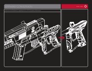
32412211113EXPLODED VIEW3568109714161517w w w . d y e p a i n t b a l l . c o mPARTS LIST1 Clamping Feed Neck2 Ball Detent Clip3 Eye Seal4 Eye Pipe5 <strong>2010</strong> <strong>DM</strong> <strong>Series</strong> Body6 FUSE Bolt7 LPR Cap8 LPR9 LPR Retaining Screw10 Solenoid11 Eye Wire12 Hyper313 Front FrameMounting Screw14 Rear FrameMounting Screw15 Ultralite Frame16 Sticky3 Grip17 On/Off Airport<strong>2010</strong> <strong>DM</strong> SERIES WARRANTYWarranty and legal informationWARRANTYDYE Precision, Inc. warrants for one year to the initial retail purchaser, from the initial dateof purchase, that the paintball marker and regulator are free from defects in materials andworkmanship, subject to the requirements, disclaimers and limitations of this warranty. Disposableparts, normal maintenance and standard wear and tear parts such as batteries, O-rings and sealsare not warrantied. The solenoid and electronic components on the marker are warrantied forsix months. This warranty does not cover scratches, nicks, improper disassembly, improper reassembly,misuse, neglect or improper storage. Modification to the product will void the warranty.The only authorized lubricant for the marker is Slick Lube. Use of any other lubricant will void yourwarranty. This warranty is limited to repair or replacement of defective parts with the customerto pay shipping costs. Warranty card and proof of purchase must be submitted to DYE Precisionfor warranty to be in effect. This warranty is not transferable. This warranty does not coverperformance. <strong>Paintball</strong> markers are non-refundable.TECHNICAL SUPPORTOur Technical Support Departments are open Monday through Friday.DYE Precision, Inc. can be reached at 858-536-5183 ext.277 from 9am to 5pm PST.DYE Europe can be reached at +44 (0) 20-8649-6330 from 9am to 5pm GMT.DYE Asia can be reached at 886 (0) 4-2407-9135 from 9am to 5pm GMT +8 hours.Additional support and international contacts are available through our web site,www.dyepaintball.com.DISCLAIMERThe specifications & photographs in this material are for information and general guidance purposesonly. Our products are continually updated and changes may be made to specification, design orappearance from time to time. These are subject to change without notice. Contents of box maytherefore vary from owner’s manual. For details of changes in design, specification or appearanceconsult your local distributor or dealer. The FUSE BOLT, Hyper3 and Slick Lube are registeredtrademarks. Design rights, copyrights and all other rights reserved. All patterns, drawings,photographs, instructions or manuals remain the intellectual property of the manufacturer.DYE Precision, Inc. U.S. Patent # 5,613,483. OTHER U.S. AND INT’L PATENTS PENDING. Covered byone or more of the following U.S. Patents, 5,613,483; 5,881,707; 5,967,133; 6,035,843 and 6,474,326.All rights will be strictly enforced.DYE Precision, Inc.10637 Scripps Summit Ct.San Diego, CA. 92131DYE Europe<strong>Dye</strong> House,7-8 Commerce WayCroydon, SurreyUnited Kingdom CR0 4XAw w w . d y e p a i n t b a l l . c o mDYE AsiaNo. 253, Guojhong Rd.Dali City, Taichung County 412Taiwan (R.O.C.)33