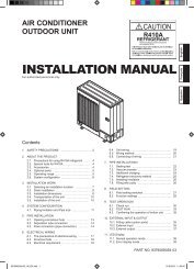
INSTALLATION MANUAL - Master
INSTALLATION MANUAL - Master
INSTALLATION MANUAL - Master

You also want an ePaper? Increase the reach of your titles
YUMPU automatically turns print PDFs into web optimized ePapers that Google loves.
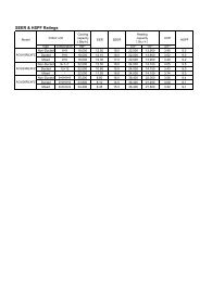
3.3. Operating range<br />
Cooling/Dry Mode Heating Mode<br />
Indoor temperature About 64 to 90 °F About 60 to 88 °F<br />
Indoor humidity About 80% or less —<br />
4. ELECTRICAL REQUIREMENT<br />
The indoor unit is powered from the outdoor unit or branch<br />
box. Do not power indoor unit from seperate power source.<br />
WARNING<br />
• Refer to local codes for acceptable cable type.<br />
Cable Cable size Remarks<br />
Connection cable 14AWG 3 cable + Ground, 1 Ø 208/230 V<br />
Max. Cable Length: Limit voltage drop to less than 2%.<br />
Increase cable gauge if voltage drop is 2% or more.<br />
5. SELECTING THE MOUNTING POSITION<br />
Decide the mounting position with the customer as follows:<br />
5.1. Indoor unit<br />
(1) Install the indoor unit level on a strong wall which is not<br />
subject to vibration.<br />
(2) The inlet and outlet ports should not be obstructed : the<br />
air should be able to blow all over the room.<br />
(3) Install the unit a dedicated electrical branch circuit.<br />
(4) Do not install the unit where it will be exposed to direct sunlight.<br />
(5) Install the unit where connection to the outdoor unit or branch<br />
box is easy.<br />
(6) Install the unit where the drain pipe can be easily installed.<br />
(7) Take servicing, etc. into consideration and leave the<br />
spaces shown in [6.1. Installation dimensions]. Also install<br />
the unit where the lter can be removed.<br />
Correct installation location is important because it is di cult<br />
to move unit after it is installed.<br />
WARNING<br />
• Select installation locations that can properly support the weight of<br />
the indoor. Install the units securely so that they do not topple or fall.<br />
CAUTION<br />
• Do not install the unit in the following areas:<br />
• Area with high salt content, such as at the seaside. It will deteriorate<br />
metal parts, causing the parts to fail or the unit to leak water.<br />
• Area lled with mineral oil or containing a large amount of splashed<br />
oil or steam, such as a kitchen.<br />
It will deteriorate plastic parts, causing the parts to fail or the unit to<br />
leak water.<br />
• Area that generates substances that adversely affect the equipment,<br />
such as sulfuric gas, chlorine gas, acid, or alkali.<br />
It will cause the copper pipes and brazed joints to corrode, which<br />
can cause refrigerant leakage.<br />
• Area that can cause combustible gas to leak, contains suspended<br />
carbon bers or ammable dust, or volatile inammables such as<br />
paint thinner or gasoline.<br />
If gas leaks and settles around the unit, it can cause a re.<br />
• Area where animals may urinate on the unit or ammonia may be<br />
generated.<br />
• Do not use the unit for special purposes, such as storing<br />
food, raising animals, growing plants, or preserving precision<br />
devices or art objects.<br />
It can degrade the quality of the preserved or stored objects.<br />
• Do not install where there is the danger of combustible gas<br />
leakage.<br />
• Do not install the unit near a source of heat, steam, or<br />
ammable gas.<br />
• Install the unit where drainage does not cause any trouble.<br />
• Install the indoor unit, outdoor unit, branch box, power supply<br />
cable, transmission cable, and remote control cable at<br />
least 40 in. (1 m) away from a television or radio receivers.<br />
The purpose of this is to prevent TV reception interference<br />
or radio noise.<br />
(Even if they are installed more than 40 in. (1 m) apart, you<br />
could still receive noise under some signal conditions.)<br />
• If children under 10 years old may approach the unit, take<br />
preventive measures so that they cannot reach the unit.<br />
• Install the indoor unit on the wall where the height from the<br />
oors more than 1800 mm (70 in.).<br />
6. <strong>INSTALLATION</strong> WORK<br />
6.1. Installation dimensions<br />
70 mm<br />
(2-3/4 in.)<br />
or over<br />
1500 mm<br />
(59-1/16 in.)<br />
or over<br />
Remote<br />
controller<br />
63 mm<br />
(2-15/32 in.)<br />
or over<br />
1800 mm<br />
(70-7/8 in.)<br />
or over<br />
Wall hook<br />
bracket<br />
(Wallcap)<br />
Remote controller holder<br />
Tapping screw (small)<br />
6.2. Indoor unit piping direction<br />
100 mm<br />
(3-15/16 in.)<br />
or over<br />
The piping can be connected in the 6 directions indicated in<br />
the following.<br />
When the piping is connected in direction 2 , 3 , 4 or 5 , cut<br />
along the piping groove in the side of the front cover with a<br />
hacksaw.<br />
2 Right<br />
outlet<br />
1 Rear outlet<br />
3 Bottom outlet<br />
(Rear)<br />
5 Left<br />
outlet<br />
6 Left rear<br />
outlet<br />
4 Left bottom outlet<br />
En-5<br />
9332279030-04_IM.indb 5<br />
9/8/2010 9:56:07 AM