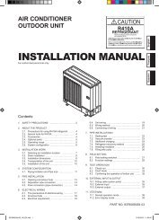
INSTALLATION MANUAL - Master
INSTALLATION MANUAL - Master
INSTALLATION MANUAL - Master

You also want an ePaper? Increase the reach of your titles
YUMPU automatically turns print PDFs into web optimized ePapers that Google loves.
7. ELECTRICAL WIRING<br />
7.1. Wiring system diagram<br />
WARNING<br />
• Every wire must be connected rmly.<br />
• No wire should be allowed to touch refrigerant tubing, the<br />
compressor or any moving part.<br />
• Loose wiring may cause the terminal to overheat or<br />
result in unit malfunction. A re hazard may also exist.<br />
Therefore, be sure all wiring is tightly connected.<br />
• Connect wires to the matching numbers of terminals.<br />
INDOOR UNIT SIDE<br />
INDOOR UNIT<br />
TERMINAL<br />
DISCONNECT<br />
SWITCH<br />
(FIELD SUPPLY)<br />
14AWG<br />
(Inter-unit)<br />
Power lines<br />
208/230 V<br />
208/230 V<br />
208/230 V<br />
Grounding line<br />
OUTDOOR UNIT<br />
or BRANCH BOX<br />
Please connect<br />
it to the specied<br />
terminal.<br />
To connect the indoor unit wires to the terminal correctly,<br />
refer to the gure for proper length.<br />
14AWG<br />
25 mm<br />
(1-13/32 in.)<br />
190 mm<br />
(7-15/32 in.)<br />
Earth wire<br />
25 mm<br />
(1-13/32 in.)<br />
175 mm<br />
(6-7/8 in.)<br />
Conduit holder<br />
Conduit connector<br />
Disconnect switch - eld supplied if required by local code.<br />
Select the correct capacity of disconnect switch according to<br />
the load.<br />
Indoor unit terminal block<br />
Earth<br />
screw<br />
Disconnect switch<br />
Outdoor unit or<br />
Branch box<br />
Please connect<br />
it to the specified<br />
terminal.<br />
7.2. How to the install the indoor unit wire<br />
harness<br />
1. Remove the screws, then remove the conduit holder.<br />
2. Fasten the indoor unit wire harness to the conduit holder<br />
using the lock nut.<br />
IMPORTANT: Refer to [7.1. Wiring system diagram] about<br />
the length of indoor unit wire harness.<br />
3. Use the screws to install the conduit holder provide with<br />
the indoor unit.<br />
4. Remove the screws, then remove the cable clamper.<br />
5. Connect indoor unit wire harness to the terminal.<br />
Refer to the wiring diagram.<br />
6. Use the screws to install the cable clamper.<br />
Lock nut<br />
Conduit holder<br />
Earth wire<br />
Screw<br />
Conduit connector<br />
En-9<br />
9332279030-04_IM.indb 9<br />
9/8/2010 9:56:10 AM