passlock 1 - Ready Remote
passlock 1 - Ready Remote
passlock 1 - Ready Remote

Create successful ePaper yourself
Turn your PDF publications into a flip-book with our unique Google optimized e-Paper software.
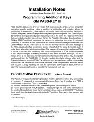
20402 & 29402<br />
VATS / PASSLOCK / TRANSPONDER<br />
Universal Alarm Bypass Module<br />
English p1<br />
Français p17<br />
Español p29
VATS / PASSLOCK / TRANSPONDER<br />
Universal Alarm Bypass Module<br />
Model #s 20402 & 29402<br />
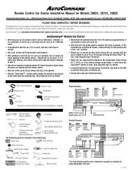
This module lets you bypass virtually any type of factory passive anti-theft system<br />
on the market today to remotely start your vehicle without permanently disabling<br />
the vehicle’s anti-theft system.<br />
In 1983, General Motors came out with their first Vehicle Anti- Theft System<br />
known as VATS which uses a resistor pellet in the key. Since that time, other more<br />
sophisticated theft systems have followed. These theft systems are still resistance<br />
based, and use a “Transponder” which is a tiny pellet or chip embeded within the<br />
the head of the ignition key.<br />
Contents:<br />
1 Universal Alarm Bypass Module<br />
1 8 position wire harness<br />
1 Transponder loop w/connector<br />
2 Cable Ties<br />
1 Instruction booklet<br />
2 Double-stick foam tape<br />
BACK VIEW<br />
8 position<br />
dip-switch<br />
Up is OFF<br />
Down is ON<br />
Variable Resistor<br />
FRONT VIEW<br />
8 position harness<br />
connector<br />
1 2 3 4 5 6 7 8<br />
Transponder Loop<br />
connector<br />
2 Resistor<br />
Measuring Pads<br />
© 2006 Directed Electronics N20402 08-06
List of vehicles and the types of security systems<br />
Liste de véhicules avec leurs types de systèmes de sécurité<br />
Lista de Vehículos y tipos de sistemas de seguridad:<br />
English Français<br />
Transponder = Transpondeur<br />
VATS = SAV<br />
Make Model Year Immobilizer<br />
Type<br />
Acura CL 1998-2003 Transponder<br />
Acura Integra 2000-01 Transponder<br />
Acura MDX 2001-06 Transponder<br />
Acura TL 1999-2006 Transponder<br />
Acura TSX 2004-06 Transponder<br />
Acura NSX 1997-2005 Transponder<br />
Acura RL 1996-2004 Transponder<br />
Audi A4 2000-04 Transponder<br />
Audi A6 2000-04 Transponder<br />
Audi A8 2000-03 Transponder<br />
Audi Allroad 2001-04 Transponder<br />
Audi S4 2002 Transponder<br />
Audi TT 2000-04 Transponder<br />
Buick LaCrosse 2005-06 Transponder<br />
Buick LeSabre 2000-05 Transponder<br />
Buick Park Avenue 2000-05 Transponder<br />
Buick Rainier 2004-06 Passlock II<br />
Buick Rendezvous 2002-06 Transponder<br />
Buick LeSabre 2000-05 Transponder<br />
Buick Park Avenue 1997-2005 Transponder<br />
Buick Skylark 1996-98 Passlock I<br />
Buick LaCrosse 2005-06 Transponder<br />
Buick Lucerne 2006 Transponder<br />
Buick Terraza 2005-06 Transponder<br />
Buick Century 1993 VATS<br />
Buick Century 1994-2005 VATS<br />
Buick Reatta 1990-91 VATS<br />
Buick Regal 1993-2004 VATS<br />
Buick Riviera 1990-99 VATS<br />
Buick Roadmaster 1993-96 VATS<br />
Cadillac CTS 2003-06 Transponder<br />
Cadillac De Ville 2000-05 Transponder<br />
Cadillac Escalade 1999-2006 Passlock II<br />
Cadillac Escalade ESV 2003-06 Passlock II<br />
Make Model Year Immobilizer<br />
Type<br />
Cadillac Escalade Ext 2002-06 Passlock II<br />
Cadillac Seville 1998-2004 Transponder<br />
Cadillac SRX 2004-06 Transponder<br />
Cadillac Catera 1997-2001 Transponder<br />
Cadillac DTS 2006 Transponder<br />
Cadillac SRX 2004-06 Transponder<br />
Cadillac Allante 1991-93 VATS<br />
Cadillac Brougham 1990-95 VATS<br />
Cadillac De Ville 1990-99 VATS<br />
Cadillac Eldorado 1990-2002 VATS<br />
Cadillac Fleetwood 1990-96 VATS<br />
Cadillac Seville 1990-97 VATS<br />
Chevrolet Astro 1998-2005 Passlock II<br />
Chevrolet Avalanche 2002-06 Passlock II<br />
Chevrolet Blazer 1998-2005 Passlock II<br />
Chevrolet Express Van 1998-2006 Passlock II<br />
Chevrolet Impala 2000-06 Passlock II<br />
Chevrolet Monte Carlo 2000-05 Passlock II<br />
Chevrolet S-10 Pickup 1998-2004 Passlock II<br />
Chevrolet Silverado 1999-2006 Passlock II<br />
Chevrolet Suburban 1998-2006 Passlock II<br />
Chevrolet Tahoe 1998-2006 Passlock II<br />
Chevrolet Trailblazer 2002-06 Passlock II<br />
Chevrolet Venture 2000-05 Transponder<br />
Chevrolet Cavalier 1995-2005 Passlock I<br />
Chevrolet Equinox 2005-06 Passlock II<br />
Chevrolet Malibu 1997-2006 Passlock II<br />
Chevrolet Monte Carlo 2000-05 Passlock II<br />
Chevrolet S-10 Pickup 1998-2004 Passlock II<br />
Chevrolet Silverado 1998-2005 Passlock II<br />
Chevrolet SSR 2003-06 Passlock II<br />
Chevrolet Aveo 2004-06 Transponder<br />
Chevrolet Impala 2006 Transponder<br />
Chevrolet Uplander 2005-06 Transponder<br />
N20402 08-06 2 © 2006 Directed Electronics
Chevrolet Camaro 1986-2002 VATS<br />
Chevrolet Caprice 1993-96 VATS<br />
Chevrolet Corvette 1984-2004 VATS<br />
Chevrolet Impala 1994-96 VATS<br />
Chevrolet Lumina 1993-2000 VATS<br />
Chevrolet Monte Carlo 1995-99 VATS<br />
Chevrolet Monte Carlo 2001-06 Passlock II<br />
Chrysler 300M 1999-2004 Transponder<br />
Chrysler Cirrus 2000 Transponder<br />
Chrysler Concorde 1998-2004 Transponder<br />
Chrysler LHS 1999-2001 Transponder<br />
Chrysler Prowler 2001-02 Transponder<br />
Chrysler PT Cruiser 2001-05 Transponder<br />
Chrysler Sebring Convertible<br />
1998-2005 Transponder<br />
Chrysler Sebring Sedan 2001-05 Transponder<br />
Chrysler Town and Country 2001-03 Transponder<br />
Chrysler Voyager 2001-03 Transponder<br />
Chrysler 300 2005-06 Transponder<br />
Chrysler Pacifica 2004-06 Transponder<br />
Chrysler PT Cruiser 2006 Transponder<br />
Chrysler Town and Country 2004-05 Transponder<br />
Chrysler Crossfire 2004-05 Transponder<br />
Chrysler Sebring Coupe 2001-05 Transponder<br />
Dodge Caravan 2001-03 Transponder<br />
Dodge Dakota pickup 2001-04 Transponder<br />
Dodge Durango 2001-03 Transponder<br />
Dodge Intrepid 1998-2004 Transponder<br />
Dodge Neon 2000-05 Transponder<br />
Dodge Ram Pickup 2002-05 Transponder<br />
Dodge Stratus 2000 Transponder<br />
Dodge Stratus Sedan 2001-05 Transponder<br />
Dodge Caliber 2007 Transponder<br />
Dodge Caravan 2004-05 Transponder<br />
Dodge Charger 2006 Transponder<br />
Dodge Dakota pickup 2005 Transponder<br />
Dodge Magnum 2005-06 Transponder<br />
Dodge Durango 2004-06 Transponder<br />
Dodge Ram Pickup 2006 Transponder<br />
Dodge Sprinter 2003-05 Transponder<br />
Dodge Stratus Coupe 2001-05 Transponder<br />
Ford Contour 1998-2000 Transponder<br />
Ford Crown Victoria 1998-2006 Transponder<br />
Ford Escape 2001-06 Transponder<br />
Ford Excursion 2000-05 Transponder<br />
Ford Expedition 1997-2006 Transponder<br />
Ford Explorer 1998-2006 Transponder<br />
Ford Explorer Sport<br />
Trac<br />
Ford F Series Light<br />
Duty<br />
2001-05 Transponder<br />
1998-2006 Transponder<br />
Ford Five Hundred 2005-06 Transponder<br />
Ford Focus 2000-06 Transponder<br />
Ford Freestar 2004-06 Transponder<br />
Ford Freestyle 2005-06 Transponder<br />
Ford Fusion 2006 Transponder<br />
Ford GT 2005-06 Transponder<br />
Ford Mustang 1996-2006 Transponder<br />
Ford Ranger 1998-2006 Transponder<br />
Ford Taurus 1998-2006 Transponder<br />
Ford Thunderbird 1997,<br />
2002-05<br />
© 2006 Directed Electronics N20402 08-06<br />
Transponder<br />
Ford Windstar 1999-2003 Transponder<br />
Ford Taurus 1996-97 Transponder<br />
GMC Denali 1999-2001 Passlock II<br />
GMC Envoy 1999-2006 Passlock II<br />
GMC Envoy XL 2002-06 Passlock II<br />
GMC Envoy XUV 2004-05 Passlock II<br />
GMC Safari 1998-2005 Passlock II<br />
GMC Safari 2005 Passlock II<br />
GMC Savana Van 1998-2006 Passlock II<br />
GMC Sierra 1998-2006 Passlock II<br />
GMC Sonoma 1998-2004 Passlock II<br />
GMC Yukon 1999-2006 Passlock II<br />
GMC Yukon XL 2000-06 Passlock II<br />
GMC Jimmy 1998-2001 Passlock II<br />
GMC Suburban 1998-2006 Passlock II<br />
Honda Prelude 1997-2001 Transponder<br />
Honda Accord 1998-2006 Transponder<br />
Honda Civic 2001-06 Transponder<br />
Honda CR-V 2002-06 Transponder<br />
Honda Element 2003-05 Transponder<br />
Honda Fit 2007 Transponder<br />
Honda Odyssey 1999-2006 Transponder<br />
Honda Pilot 2003-05 Transponder<br />
Honda Ridgeline 2006 Transponder<br />
Honda Accord Hybrid 2005 Transponder<br />
Honda Insight 2000-05 Transponder<br />
Honda Odyssey 1998 Transponder
Honda S2000 2000-05 Transponder<br />
Hummer H2 2003-05 Transponder<br />
Hyundai Accent 2004-05 Transponder<br />
Hyundai Azera 2006 Transponder<br />
Hyundai Elantra 2001-05 Transponder<br />
Hyundai Santa Fe 2003-05 Transponder<br />
Hyundai Sonata 2004-06 Transponder<br />
Hyundai Tiburon 2003-05 Transponder<br />
Hyundai Tucson 2005 Transponder<br />
Hyundai XG300 2001 Transponder<br />
Hyundai XG350 2002-05 Transponder<br />
Infiniti FX35/FX45 2003-05 Transponder<br />
Infiniti G20 2000-02 Transponder<br />
Infiniti G35 Coupe 2003-05 Transponder<br />
Infiniti G35 Sedan 2003-05 Transponder<br />
Infiniti I30 1999-2001 Transponder<br />
Infiniti I35 2002-04 Transponder<br />
Infiniti M45 2003-04 Transponder<br />
Infiniti Q45 1998-2005 Transponder<br />
Infiniti QX4 1999-2003 Transponder<br />
Infiniti QX56 2004-05 Transponder<br />
Isuzu Ascender 2003-06 Passlock II<br />
Isuzu Hombre 1998-2000 Passlock II<br />
Isuzu Axiom 2003-04 Transponder<br />
Isuzu Rodeo 2003-04 Transponder<br />
Isuzu Rodeo Sport 2003 Transponder<br />
Jaguar S-type 2000-05 Transponder<br />
Jaguar XJ Series 2004-05 Transponder<br />
Jaguar XJ8 1998-2003 Transponder<br />
Jaguar XJR 1998-2003 Transponder<br />
Jaguar XK Series 2004 Transponder<br />
Jaguar XK Series 2005 Transponder<br />
Jaguar XK8 1998-2003 Transponder<br />
Jaguar XKR 2000-03 Transponder<br />
Jaguar X-type 2002-05 Transponder<br />
Jeep Cherokee 1999-2001 Transponder<br />
Jeep Grand Cherokee 1999-2005 Transponder<br />
Jeep Liberty 2002-05 Transponder<br />
Jeep Wrangler 1998-2005 Transponder<br />
Jeep Commander 2006 Transponder<br />
Kia Amanti 2004-05 Transponder<br />
Kia Optima 2005 Transponder<br />
Kia Spectra (2.0L) 2004-05 Transponder<br />
Kia Sportage 2005 Transponder<br />
Land Rover Discovery Series II 2000-04 Transponder<br />
Land Rover Freelander 2002-05 Transponder<br />
Land Rover LR3 2005 Transponder<br />
Land Rover Range Rover 1999-2005 Transponder<br />
Lexus ES 300 1998-2003 Transponder<br />
Lexus GS 300 1998-2005 Transponder<br />
Lexus GS 400 1998-2000 Transponder<br />
Lexus GS 430 2001-05 Transponder<br />
Lexus IS 300 2001-05 Transponder<br />
Lexus LS 400 1998-2000 Transponder<br />
Lexus LX 470 1998-2002 Transponder<br />
Lexus RX 300 1998-2003 Transponder<br />
Lexus SC 300 1998-2000 Transponder<br />
Lexus SC 400 1998-2000 Transponder<br />
Lexus ES 330 2004-06 Transponder<br />
Lexus GX 470 2003-06 Transponder<br />
Lexus LS 400 1997 Transponder<br />
Lexus LS 430 2001-06 Transponder<br />
Lexus LX 470 2003-06 Transponder<br />
Lexus RX 330 2004-06 Transponder<br />
Lexus RX 400h 2006 Transponder<br />
Lexus SC 430 2002-06 Transponder<br />
Lincoln Aviator 2003-05 Transponder<br />
Lincoln Blackwood 2002 Transponder<br />
Lincoln Continental 1998-2002 Transponder<br />
Lincoln LS 2000-06 Transponder<br />
Lincoln Mark LT 2006 Transponder<br />
Lincoln Navigator 1998-2006 Transponder<br />
Lincoln Town Car 1998-2006 Transponder<br />
Lincoln Zephyr 2006 Transponder<br />
Lincoln Mark VIII 1997-98 Transponder<br />
Mazda 3 2004-05 Transponder<br />
Mazda 6 2003-05 Transponder<br />
Mazda B 2500, B 3000,<br />
B 4000<br />
1999-2000 Transponder<br />
Mazda B Series 2001-05 Transponder<br />
Mazda RX-8 2004-05 Transponder<br />
Mazda Tribute 2001-05 Transponder<br />
Mazda 5 2006 Transponder<br />
Mazda 626 1998-2002 Transponder<br />
Mazda CX-7 2007 Transponder<br />
Mazda Miata 2001-06 Transponder<br />
Mazda Millenia 1998-2002 Transponder<br />
Mazda MPV 2000-05 Transponder<br />
Mercedes<br />
Benz<br />
C 230 1998-2000 SWITCH-<br />
BLADE<br />
KEYS ONLY<br />
N20402 08-06 4 © 2006 Directed Electronics
Mercedes<br />
Benz<br />
Mercedes<br />
Benz<br />
Mercedes<br />
Benz<br />
Mercedes<br />
Benz<br />
Mercedes<br />
Benz<br />
Mercedes<br />
Benz<br />
Mercedes<br />
Benz<br />
Mercedes<br />
Benz<br />
Mercedes<br />
Benz<br />
Mercedes<br />
Benz<br />
Mercedes<br />
Benz<br />
Mercedes<br />
Benz<br />
Mercedes<br />
Benz<br />
Mercedes<br />
Benz<br />
Mercedes<br />
Benz<br />
C 280 1998-2000 SWITCH-<br />
BLADE<br />
KEYS ONLY<br />
C Class 2001-02 SWITCH-<br />
BLADE<br />
KEYS ONLY<br />
CL Class 1998-99 SWITCH-<br />
BLADE<br />
KEYS ONLY<br />
CLK Class 1998 SWITCH-<br />
BLADE<br />
KEYS ONLY<br />
CLK Class 1999-2002 SWITCH-<br />
BLADE<br />
KEYS ONLY<br />
E Class 1997-2002 SWITCH-<br />
BLADE<br />
KEYS ONLY<br />
ML 320 1998-2000 SWITCH-<br />
BLADE<br />
KEYS ONLY<br />
ML 430 1999-2000 SWITCH-<br />
BLADE<br />
KEYS ONLY<br />
ML Class 2001-02 SWITCH-<br />
BLADE<br />
KEYS ONLY<br />
S 320 1997 SWITCH-<br />
BLADE<br />
KEYS ONLY<br />
S 420 1997 SWITCH-<br />
BLADE<br />
KEYS ONLY<br />
S 500 1997 SWITCH-<br />
BLADE<br />
KEYS ONLY<br />
S Class 1998-2002 SWITCH-<br />
BLADE<br />
KEYS ONLY<br />
SL Class 1998-99 SWITCH-<br />
BLADE<br />
KEYS ONLY<br />
SLK Class 1998-2002 SWITCH-<br />
BLADE<br />
KEYS ONLY<br />
Mercury Cougar 1999-2002 Transponder<br />
Mercury Grand Marquis 1999-2006 Transponder<br />
Mercury Marauder 2003-04 Transponder<br />
Mercury Mariner 2005-06 Transponder<br />
Mercury Milan 2006 Transponder<br />
Mercury Montego 2005-06 Transponder<br />
Mercury Monterey 2004 Transponder<br />
Mercury Monterey 2005-06 Transponder<br />
Mercury Mountaineer 1998-2006 Transponder<br />
Mercury Mystique 1998-2000 Transponder<br />
Mercury Sable 1996-2005 Transponder<br />
Mercury Cougar 1997 Transponder<br />
Mercury Grand Marquis 1998 Transponder<br />
Mercury Mountaineer 1997 Transponder<br />
Mini Cooper 2002-05 Transponder<br />
Mitsubishi Diamante 2000-04 Transponder<br />
Mitsubishi Eclipse 2000-06 Transponder<br />
Mitsubishi Endeavor 2004-05 Transponder<br />
Mitsubishi Galant 2000-05 Transponder<br />
Mitsubishi Lancer 2003-05 Transponder<br />
Mitsubishi Montero 2001-05 Transponder<br />
Mitsubishi Montero Sport 2000-04 Transponder<br />
Mitsubishi Outlander 2004-05 Transponder<br />
Mitsubishi Raider 2006 Transponder<br />
Nissan 350Z 2003-05 Transponder<br />
Nissan Altima 2000-05 Transponder<br />
Nissan Armada 2005 Transponder<br />
Nissan Frontier 2005 Transponder<br />
Nissan Maxima 1999-2005 Transponder<br />
Nissan Murano 2003-05 Transponder<br />
Nissan Pathfinder 1999-2005 Transponder<br />
Nissan Pathfinder 2000-05 Transponder<br />
Nissan Pathfinder Armada 2004 Transponder<br />
Nissan Quest 2004-05 Transponder<br />
Nissan Sentra 2000-05 Transponder<br />
Nissan Titan 2004-05 Transponder<br />
Nissan Xterra 2005 Transponder<br />
Oldsmobile Alero 2000-04 Passlock II<br />
Oldsmobile Aurora 1995-99 VATS<br />
Oldsmobile Aurora 2001-03 Transponder<br />
Oldsmobile Bravada 1999-2004 Passlock II<br />
Oldsmobile Intrigue 1998-2002 Passlock II<br />
Oldsmobile Silhouette 2000-04 Transponder<br />
Oldsmobile Achieva 1996-98 Passlock I<br />
Oldsmobile Cutlass 1997-99 Passlock II<br />
Oldsmobile Cutlass Ciera 1995-96 VATS<br />
Oldsmobile Cutlass Supreme 1995-97 VATS<br />
Oldsmobile Eighty-Eight 1995-97 VATS<br />
Oldsmobile Eighty-Eight LSS 1998-99 VATS<br />
Oldsmobile Ninety-Eight 1992-98 VATS<br />
Oldsmobile Regency 1997-98 VATS<br />
Plymouth Breeze 2000 Transponder<br />
Plymouth Neon 2000-01 Transponder<br />
Plymouth Prowler 1999-2000 Transponder<br />
Pontiac Aztek 2001-05 Passlock II<br />
Pontiac Bonneville 1992-2005 VATS<br />
Pontiac Grand Am 1996-98 Passlock I<br />
© 2006 Directed Electronics N20402 08-06
Pontiac Grand Am 1999-2005 Passlock II<br />
Pontiac Montana 2000-05 Transponder<br />
Pontiac Sunfire 2000-05 Passlock II<br />
Pontiac Transport 2000 Transponder<br />
Pontiac Grand Prix 2000-05 Transponder<br />
Pontiac Sunfire 1995-2005 Passlock I<br />
Pontiac Sunfire 1996-99 Passlock I<br />
Pontiac Sunfire 2000-05 Passlock II<br />
Pontiac Torrent 2006 Passlock II<br />
Pontiac Montana SV6 2005-06 Transponder<br />
Pontiac Solstice 2006 Transponder<br />
Pontiac Firebird 1986-2002 VATS<br />
Porsche 911 Carrera 993 1995-98 Transponder<br />
Porsche 911 Carrera 996 1999-2004 Transponder<br />
Porsche Boxster 1997-2004 Transponder<br />
Saab 9-3 1999-2004 Transponder<br />
Saab 9-5 1999-2004 Transponder<br />
Saab 9-7X 2005 Transponder<br />
Saturn S-Series 2000-02 Passlock II<br />
Saturn L-Series 2000-05 Passlock II<br />
Saturn S-Series 2000-02 Passlock II<br />
Saturn Vue 2002-05 Passlock II<br />
Saturn Relay 2005-06 Transponder<br />
Saturn Sky 2007 Transponder<br />
Scion tC 2005-06 Transponder<br />
Subaru B9 Tribeca 2006 Transponder<br />
Subaru Forester 2005-06 Transponder<br />
Subaru Impreza 2005-06 Transponder<br />
Subaru Legacy 2005-06 Transponder<br />
Subaru Outback 2005-06 Transponder<br />
Suzuki Grand Vitara 2006 Transponder<br />
Suzuki Verona 2004-06 Transponder<br />
Toyota 4Runner 1999-2002 Transponder<br />
Toyota Avalon 1998-2004 Transponder<br />
Toyota Camry 1998-2004 Transponder<br />
Toyota Highlander 2001-03 Transponder<br />
Toyota Land Cruiser 1998-2002 Transponder<br />
Toyota RAV4 2001-03 Transponder<br />
Toyota Sequoia 2001-02 Transponder<br />
Toyota Sienna 1999-2003 Transponder<br />
Toyota Solara 1999-2003 Transponder<br />
Toyota 4Runner 2003-06 Transponder<br />
Toyota Avalon 2005-06 Transponder<br />
Toyota Camry 2005-07 Transponder<br />
Toyota Corolla 2005-06 Transponder<br />
Toyota Highlander 2004-06 Transponder<br />
Toyota Highlander Hybrid 2006 Transponder<br />
Toyota Land Cruiser 2003-06 Transponder<br />
Toyota Matrix 2005-06 Transponder<br />
Toyota MR2 2000-05 Transponder<br />
Toyota Prius 2001-05 Transponder<br />
Toyota RAV4 2004-06 Transponder<br />
Toyota Sequoia 2003-06 Transponder<br />
Toyota Sienna 2004-06 Transponder<br />
Toyota Solara 2004-06 Transponder<br />
Toyota Tacoma 2005-06 Transponder<br />
Toyota Yaris 2006-07 Transponder<br />
Volkswagen Beetle 1999-2004 Transponder<br />
Volkswagen Cabrio 2000-02 Transponder<br />
Volkswagen Eurovan 2001-03 Transponder<br />
Volkswagen Golf w/ power<br />
windows<br />
Volkswagen Golf w/o power<br />
windows<br />
Volkswagen GTI w/ power<br />
windows<br />
Volkswagen GTI w/o power<br />
windows<br />
2000-04 Transponder<br />
2000-04 Transponder<br />
2000-04 Transponder<br />
2000-04 Transponder<br />
Volkswagen Jetta V 2005 Transponder<br />
Volkswagen Jetta w/ power<br />
windows<br />
Volkswagen Jetta w/o power<br />
window<br />
2000-04 Transponder<br />
2000-04 Transponder<br />
Volkswagen Passat 2000-04 Transponder<br />
Volvo C70 1998-2004 Transponder<br />
Volvo S40 2000-2005 Transponder<br />
Volvo S60 2001-04 Transponder<br />
Volvo S70 1998-2000 Transponder<br />
Volvo S80 1999-2004 Transponder<br />
Volvo S90 1998-99 Transponder<br />
Volvo V40 2000-04 Transponder<br />
Volvo V50 2005 Transponder<br />
Volvo V70 1998-2004 Transponder<br />
Volvo V90 1998-99 Transponder<br />
Volvo XC70 2003-04 Transponder<br />
Volvo XC90 2003-04 Transponder<br />
N20402 08-06 6 © 2006 Directed Electronics
Determine which type system you have in your vehicle. If unsure -- follow the<br />
chart on the previous pages to determine the system you have. There are several<br />
types of systems as outlined below:<br />
General Motors VATS and PASSLOCK 1 and PASSLOCK 2 theft systems. For<br />
these, you will be required to dial-in a resistor value which matches the one on your<br />
security system. The method is described on the following pages for each type<br />
system using the dip switches and the variable resistor. The variable resistor is a<br />
10 turn potentiometer which can be dialed up from zero ohms to 1,000 ohms.<br />
SATURN vehicles up to the 2000 model year simply hook up to the Universal<br />
Alarm Bypass Module as shown on page 13. If you have a 2000 model year or<br />
later Saturn vehicle, see page 14.<br />
TRANSPONDER / PASSKEY 3 / P.A.T.S. systems require a transponder (or<br />
extra key) to be used with our system. Follow the directions beginning on page<br />
14.<br />
© 2006 Directed Electronics N20402 08-06
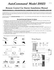
Use this chart with VATS, PASSLOCK 1 and PASSLOCK 2.<br />
Dip Switch # 2 3 4 5 6<br />
Resistor Value 0.825 1.65 3.32 6.65 13.3 Final Resistance (k ohms)<br />
ON ON ON ON ON 0.000 +Variable Resistor Value<br />
OFF ON ON ON ON 0.825 +Variable Resistor Value<br />
ON OFF ON ON ON 1.650 +Variable Resistor Value<br />
OFF OFF ON ON ON 2.475 +Variable Resistor Value<br />
ON ON OFF ON ON 3.320 +Variable Resistor Value<br />
OFF ON OFF ON ON 4.145 +Variable Resistor Value<br />
ON OFF OFF ON ON 4.970 +Variable Resistor Value<br />
OFF OFF OFF ON ON 5.795 +Variable Resistor Value<br />
ON ON ON OFF ON 6.650 +Variable Resistor Value<br />
OFF ON ON OFF ON 7.475 +Variable Resistor Value<br />
ON OFF ON OFF ON 8.300 +Variable Resistor Value<br />
OFF OFF ON OFF ON 9.125 +Variable Resistor Value<br />
ON ON OFF OFF ON 9.970 +Variable Resistor Value<br />
OFF ON OFF OFF ON 10.795 +Variable Resistor Value<br />
ON OFF OFF OFF ON 11.620 +Variable Resistor Value<br />
OFF OFF OFF OFF ON 12.445 +Variable Resistor Value<br />
ON ON ON ON OFF 13.300 +Variable Resistor Value<br />
OFF ON ON ON OFF 14.125 +Variable Resistor Value<br />
ON OFF ON ON OFF 14.950 +Variable Resistor Value<br />
OFF OFF ON ON OFF 15.775 +Variable Resistor Value<br />
ON ON OFF ON OFF 16.620 +Variable Resistor Value<br />
OFF ON OFF ON OFF 17.445 +Variable Resistor Value<br />
ON OFF OFF ON OFF 18.270 +Variable Resistor Value<br />
OFF OFF OFF ON OFF 19.095 +Variable Resistor Value<br />
ON ON ON OFF OFF 19.950 +Variable Resistor Value<br />
OFF ON ON OFF OFF 20.775 +Variable Resistor Value<br />
ON OFF ON OFF OFF 21.600 +Variable Resistor Value<br />
OFF OFF ON OFF OFF 22.425 +Variable Resistor Value<br />
ON ON OFF OFF OFF 23.270 +Variable Resistor Value<br />
OFF ON OFF OFF OFF 24.095 +Variable Resistor Value<br />
ON OFF OFF OFF OFF 24.920 +Variable Resistor Value<br />
OFF OFF OFF OFF OFF 25.745 +Variable Resistor Value<br />
All resistor values shown are in ‘K-ohms’ -- or 1,000 ohms. Thus the<br />
1.650 value shown in the third row is 1,650 ohms or 1.65 K ohms.<br />
DipSwitch #1 Dip Switch #7 Dip Switch #8<br />
VATS OFF OFF OFF<br />
PASSLOCK 1 ON ON OFF<br />
PASSLOCK 2 OFF OFF OFF<br />
N20402 08-06 8 © 2006 Directed Electronics
VATS:<br />
Before performing this set up, make sure the vehicle will start with the transmitter<br />
if you leave the ignition key in the key cylinder.<br />
1. Put dip switch 1, 7 and 8 into the OFF (up) position<br />
2. Measure the resistance of the key. It should be between 392 ohms and 11,800<br />
ohms. To do this, put the ohm meter probes on each side of the key pellet. This<br />
value should be close to one of the following (all values in ohms): 392, 523, 681,<br />
887, 1.13K, 1.47K, 1.87K, 3.01K, 3.74K, 4.75K, 6.04K, 7.5K, 9.53K, 11.8K.<br />
3. Locate the closest value which is less than your desired value on the chart on<br />
page 8. Set dip-switches 2 through 6 as shown on page 8.<br />
4. Put your ohm meter (multi-meter) probes on the two silver resistance measuring<br />
pads through the opening shown in the drawing -- making good contact with<br />
these two silver pads on the board. (See drawing on page 1). Or put your two<br />
probes into the two holes on the bottom of the case making contact with the<br />
underside of the silver pads. Either contact point method will work.<br />
5. With the probes held firmly, finish reaching the final resistance value needed<br />
for your system by turning the screw on the variable resistor on the side of the<br />
unit next to the dip switches. Turn the screw until the resistance value matches<br />
the resistance value of the key.<br />
6. Locate the pair of VATS wires (sometimes White/Black striped and Purple/<br />
Black striped). These wires are often in a plastic tube. Be careful not to cut<br />
into the Yellow Air Bag wires! The Air Bag wires are often in a yellow plastic<br />
tube that is clearly marked. The VATS wires run from the ignition switch down<br />
the column under the dash. Connect the Universal Alarm Bypass Module using<br />
the diagram below.<br />
Dip Switch #1 Off<br />
Dip Switch #7 Off<br />
Dip Switch #8 Off<br />
White/Green to Status wire<br />
*See page 16 if you do not have a Status wire on your remote<br />
starter<br />
© 2006 Directed Electronics N20402 08-06
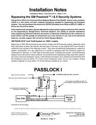
PASSLOCK 1:<br />
1. Put dip switches 1 and 7 in the ON (down) position and dip switch 8 in the OFF<br />
(up) position.<br />
2. Remove the bottom half of the steering column shroud.<br />
3. Locate the small three wire harness (with White, Black and Yellow wires)<br />
running down from the ignition key cylinder on the top right hand side of the<br />
steering column into the instrument panel. These wires are usually the smallest<br />
wires in the harness.<br />
4. Cut the Yellow wire in half and strip back both ends. Remove some of the<br />
insulation on the Black wire without cutting the wire. The White wire is not<br />
used.<br />
5. Turn the ignition key to the “ON” or “RUN” position and place the vehicle into<br />
reverse.<br />
6. With the ignition key still in and turned to the “RUN” position, measure the<br />
resistance between the key side of the Yellow wire (connected to the + positive<br />
lead of your digital meter) and the Black wire (connected to the - negative side<br />
of your digital meter).<br />
7. Turn the ignition key to the “START” position and release it. Denote the<br />
resistance reading as this will be the resistance that will need to be duplicated.<br />
Repeat this step several times to verify that you have a consistent reading.<br />
8. When you have identified the correct resistance use the chart on page 8 to set<br />
the resistance on the bypass module. Locate the closest value which is less than<br />
your desired value. Set dip-switches 2 through 6 to match the chart on page 8<br />
for this value.<br />
9. Put your ohm meter (multi-meter) probes on the two silver resistance measuring<br />
pads through the opening shown in the drawing -- making good contact with<br />
these two silver pads on the board. (See drawing on page 1). Or put your two<br />
probes into the two holes on the bottom of the case making contact with the<br />
underside of the silver pads. Either contact point method will work.<br />
10. With the probes held firmly -- dial-in the final resistance value needed for your<br />
system by turning the screw on the variable resistor on the side of the unit<br />
next to the dip switches. Turn the screw until the resistance value matches the<br />
resistance value of the key.<br />
11. Locate the Black “Bulb Test” wire on the left side of the steering column in<br />
cavity “D” or “E” of the Black 5-way connector, just above the main ignition<br />
switch connector. This is a different wire than the Black wire mentioned in<br />
the above steps.<br />
12. Connect the bypass module using the diagram below. Be sure to tape over any<br />
connections to not leave any exposed wires.<br />
N20402 08-06 0 © 2006 Directed Electronics
PASSLOCK 1<br />
WHITE/GREEN to WHITE/<br />
BLACK Status wire from<br />
the remote starter.*<br />
*See page 16 if you do not have a Status wire<br />
To verify the Passlock installation has the correct resistance value<br />
and that the installation is correct -- hold the WHITE/GREEN wire<br />
to ground and start the vehicle with the key. If the vehicle starts<br />
and stays running - the installation is correct.<br />
PASSLOCK 2:<br />
1. Turn dip switches 1, 7, and 8 to the OFF (up) position.<br />
2. Remove the bottom half of the steering column shroud.<br />
3. Locate the small three wire harness (with Red/White, Yellow and Orange/<br />
Black wires on trucks and White, Yellow and Black on cars) that come<br />
off the ignition lock cylinder. These are usually the smallest wires.<br />
4. Cut the Yellow wire in half and strip back both ends. Remove the insulation<br />
on the Orange/Black wire (trucks) or the Black wire (cars) without cutting<br />
the wire. The Red/White or White wire is not used.<br />
5. Turn the key to the “Run” position and place the vehicle in Reverse.<br />
6. Connect the key side of the Yellow wire to the + positive lead of your digital<br />
meter and the Black wire (cars) or Orange/Black wire (trucks) to the - negative<br />
lead of your digital meter.<br />
7. Turn the ignition key to the “START” position and release it. Denote the<br />
resistance reading as this will be the resistance that will need to be duplicated.<br />
Repeat this step several times to verify that you have a consistent reading.<br />
© 2006 Directed Electronics N20402 08-06
8. When you have identified the correct resistance use the chart on page 8 to set<br />
the resistance on the bypass module. Locate the closest value which is less<br />
than your desired value. Set dip-switches 2 through 6 to match the chart on<br />
page 8 with this value.<br />
9. Put your ohm meter (multi-meter) probes on the two silver resistance measuring<br />
pads through the opening shown in the drawing -- making good contact with<br />
these two silver pads on the board. (See drawing on page 1). Or put your two<br />
probes into the two holes on the bottom of the case making contact with the<br />
underside of the silver pads. Either contact point method will work.<br />
10. With the probes held firmly -- dial-in the final resistance value needed for your<br />
system by turning the screw on the variable resistor on the side of the unit<br />
next to the dip switches. Turn the screw until the resistance value matches<br />
the resistance value of the key.<br />
11. Connect the bypass module using the diagram on the next page. Be sure to<br />
tape over any connections to not leave any exposed wires.<br />
To verify that this installation is correct -- hold the WHITE/GREEN wire<br />
and the GRAY/BLACK wire to ground and start the vehicle with the key.<br />
If the vehicle starts and stays running - the installation is correct.<br />
Dip Switch #1 Off<br />
Dip Switch #7 Off<br />
Dip Switch #8 Off<br />
WHITE/GREEN TO WHITE/BLACK<br />
Status output from car starter<br />
(or to constant negative ground<br />
output when remote starter is<br />
*See page 16 if you do not have a Status wire<br />
N20402 08-06 2 © 2006 Directed Electronics
SATURN:<br />
Saturn vehicles up to the 2000 model year with factory keyless entry have a<br />
unique bypass.<br />
1. Set all dip switches to the OFF (up) position.<br />
2. Locate the Alarm Module behind the right rear quarter trim panel (trunk area).<br />
Connect the Pink and Yellow/Black wires of Connector J and D of the alarm<br />
module as shown.<br />
3. Cut the Pink wire in half and connect as shown.<br />
Dip Switch #1 Off<br />
Dip Switch #7 Off<br />
Dip Switch #8 Off<br />
WHITE/GREEN TO WHITE/BLACK<br />
Status output from car starter (or<br />
to constant negative ground output<br />
when remote starter is activated).*<br />
*See page 16 if you do not have a Status wire<br />
© 2006 Directed Electronics N20402 08-06
TRANSPONDER / PASSKEY 3 / P.A.T.S.:<br />
‘Smart Key’ & other Transponder systems<br />
Note: For this type of security system - you must sacrifice one of the spare keys that<br />
comes with the car. This key will be used for the transponder. The dealership<br />
can progam a spare key, but make sure they program all keys to the vehicle<br />
since learning just one transponder could erase all other key transponders<br />
(including the key used for the Bypass Module).<br />
1. Set all dip switches on the bypass module to the OFF (up) position.<br />
2. Remove the transponder from the key (there maybe a door on the top of the<br />
key that can be opened and the transponder can be removed). Or, the entire<br />
key may be mounted inside the Bypass Module. Be sure to cut the key in half<br />
or grind off some of the teeth to render it unusable.<br />
3. Pull apart the case and place the transponder, or the head of the key, inside the<br />
10 wire loop on the circuit board. Transponders are directional and must be<br />
placed along the same direction that the key would lay. Use the double stick<br />
foam tape provided -- one layer on the circuit board and then the transponder,<br />
or key, and finally the second double-stick foam tape layer on top of it to<br />
hold key securly in place. Make sure the white wires inside the module do not<br />
crisscross each other.<br />
Place Key with Transponder inside case on pc<br />
board as shown. Use double stick tape to hold<br />
to the key in place.<br />
N20402 08-06 4 © 2006 Directed Electronics
4. The transponder LOOP goes underneath the steering column and up toward<br />
the ignition key cylinder and needs to be positioned so that there are 2 turns<br />
around the ignition key cylinder as shown below. Transponder systems often<br />
have a black plastic ring around the ignition lock switch. This is the vehicle’s<br />
transponder pick-up antenna. It is important that the two loops of the Bypass<br />
Module be mounted on or as close to this black plastic ring as possible. Slide<br />
the tube up toward the ignition switch to tighten up the loops of wire. Tape in<br />
place to hold. Plug the other end of the transponder loop into the Universal<br />
Alarm Bypass Module.<br />
5. Now start the vehicle with the remote starter. If the vehicle starts and runs<br />
for at least 30 seconds the transponder bypass is correct. Note: If the vehicle<br />
does not start with the remote starter, try adjusting or changing the position<br />
of the transponder in the Bypass Module or adjusting the position of the two<br />
loop wire around the transponder pick-up antenna mentioned above.<br />
White/Green to Status wire of <strong>Remote</strong> Starter<br />
Note: The key that the transponder was removed from will no longer start<br />
the vehicle.<br />
© 2006 Directed Electronics N20402 08-06
For Car Starters that do not have a Status output: You will need a Status<br />
output from your remote car starter for each kind of immobilizer listed on the<br />
preceding pages. Most of our remote starters use the WHITE/BLACK wire in the<br />
control harness as the Status output. If you have a brand of remote car starter that<br />
does not have a Status output, follow the relay hook-up below using Bosch 30 Amp<br />
relays for creating the Status output.<br />
Status output to control<br />
alarm bypass module<br />
N20402 08-06 6 © 2006 Directed Electronics
Français
SAV / PASSLOCK / TRANSPONDEUR<br />
Module universel de contournement d’alarme<br />
Modèles de série 20402 & 29402<br />
Ce module permet de contourner presque tout type de système antivol passif intégré<br />
actuellement sur le marché et de faire démarrer votre véhicule à distance sans<br />
désactiver en permanence son système antivol.<br />
En 1983, General Motors a inventé son premier système antivol, le VATS (SAV<br />
en français), qui utilise une pastille de résistance intégrée à la clé. Depuis lors,<br />
d’autres systèmes plus avancés ont vu le jour. Ils sont encore aujourd’hui basés<br />
sur une résistance et utilisent un transpondeur, une petite pastille ou puce intégrée<br />
à la tête de la clé de contact.<br />
Contenu:<br />
1. 1 module universel de contournement d’alarme<br />
2. 1 faisceau électrique à 8 positions<br />
3. 1 boucle de transpondeur avec raccord<br />
4. 2 attaches de câbles<br />
5. 1 livret d’instructions<br />
6. 2 isolants adhésifs à double face<br />
ARRIÈRE<br />
Commutateur DIP à 8<br />
positions<br />
La position relevée est OFF<br />
La position abaissée est<br />
ON<br />
Résistance variable<br />
AVANT<br />
Raccord de faisceau à 8<br />
positions<br />
1 2 3 4 5 6 7 8<br />
Raccord de boucle de<br />
transpondeur<br />
2 contacts de mesure de<br />
résistance<br />
N20402 08-06 8 © 2006 Directed Electronics
Trouvez quel type de système protège votre véhicule. Dans le doute, utilisez le<br />
tableau de la pages précédente (p2 - p6) pour le savoir. Il existe plusieurs types de<br />
systèmes, tel qu’expliqué ci-dessous.<br />
Pour les systèmes antivol SAV, PASSLOCK 1 et PASSLOCK 2 de General Motors,<br />
vous devrez régler la valeur de la résistance pour correspondre à celle de votre<br />
système de sécurité. La méthode est décrite aux pages suivantes pour chaque type<br />
de système. Utilisez les commutateurs DIP et la résistance variable. Cette résistance<br />
est un potentiomètre à dix échelons qui peut être réglé de zéro à 1 000 ohms.<br />
Les véhicules SATURN datant d’avant 2000 sont simplement branchés au module<br />
universel de contournement d’alarme tel qu’expliqué à la page 25. Si votre<br />
Saturn date de 2000 ou plus tard, référez-vous à la page 26.<br />
Dans le cas des systèmes de type TRANSPONDEUR, PASSKEY 3 et<br />
P.A.T.S., un transpondeur ou une clé supplémentaire devra être utilisée avec<br />
notre système. Suivez les instructions des pages 26 et 27.<br />
© 2006 Directed Electronics N20402 08-06
Utilisez ce tableau pour les systèmes SAV, PASSLOCK 1 et PASSLOCK 2.<br />
Commutateur Dip # 2 3 4 5 6<br />
Valeur résistance 0.825 1.65 3.32 6.65 13.3 Résistance finale (kilo ohms)<br />
ON ON ON ON ON 0.000 +valeur de résistance variable<br />
OFF ON ON ON ON 0.825 +valeur de résistance variable<br />
ON OFF ON ON ON 1.650 +valeur de résistance variable<br />
OFF OFF ON ON ON 2.475 +valeur de résistance variable<br />
ON ON OFF ON ON 3.320 +valeur de résistance variable<br />
OFF ON OFF ON ON 4.145 +valeur de résistance variable<br />
ON OFF OFF ON ON 4.970 +valeur de résistance variable<br />
OFF OFF OFF ON ON 5.795 +valeur de résistance variable<br />
ON ON ON OFF ON 6.650 +valeur de résistance variable<br />
OFF ON ON OFF ON 7.475 +valeur de résistance variable<br />
ON OFF ON OFF ON 8.300 +valeur de résistance variable<br />
OFF OFF ON OFF ON 9.125 +valeur de résistance variable<br />
ON ON OFF OFF ON 9.970 +valeur de résistance variable<br />
OFF ON OFF OFF ON 10.795 +valeur de résistance variable<br />
ON OFF OFF OFF ON 11.620 +valeur de résistance variable<br />
OFF OFF OFF OFF ON 12.445 +valeur de résistance variable<br />
ON ON ON ON OFF 13.300 +valeur de résistance variable<br />
OFF ON ON ON OFF 14.125 +valeur de résistance variable<br />
ON OFF ON ON OFF 14.950 +valeur de résistance variable<br />
OFF OFF ON ON OFF 15.775 +valeur de résistance variable<br />
ON ON OFF ON OFF 16.620 +valeur de résistance variable<br />
OFF ON OFF ON OFF 17.445 +valeur de résistance variable<br />
ON OFF OFF ON OFF 18.270 +valeur de résistance variable<br />
OFF OFF OFF ON OFF 19.095 +valeur de résistance variable<br />
ON ON ON OFF OFF 19.950 +valeur de résistance variable<br />
OFF ON ON OFF OFF 20.775 +valeur de résistance variable<br />
ON OFF ON OFF OFF 21.600 +valeur de résistance variable<br />
OFF OFF ON OFF OFF 22.425 +valeur de résistance variable<br />
ON ON OFF OFF OFF 23.270 +valeur de résistance variable<br />
OFF ON OFF OFF OFF 24.095 +valeur de résistance variable<br />
ON OFF OFF OFF OFF 24.920 +valeur de résistance variable<br />
OFF OFF OFF OFF OFF 25.745 +valeur de résistance variable<br />
Toutes les valeurs de résistance sont affichées en kilo-ohms (1 000 ohms). Par<br />
exemple, la valeur “1.650” de la troisième rangée correspond à 1 650 ohms ou<br />
1,65 kilo-ohms.<br />
Commutateur Dip#1 Dip #7 Dip #8<br />
SAV OFF OFF OFF<br />
PASSLOCK 1 ON ON OFF<br />
PASSLOCK 2 OFF OFF OFF<br />
N20402 08-06 20 © 2006 Directed Electronics
SAV:<br />
Avant de commencer l’installation, assurez-vous que le transmetteur fait démarrer le véhicule<br />
quand la clé de contact est dans la serrure.<br />
1. Mettez les commutateurs DIP 1, 7 et 8 en position OFF (relevée).<br />
2. Mesurez la résistance de la clé. Elle devrait se situer entre 392 et 11 800 ohms. Pour ce faire,<br />
placez les sondes de l’ohmmètre de chaque côté de la pastille de la clé. La valeur trouvée devrait<br />
être proche de l’une des suivantes (en ohms): 392, 523, 681, 887, 1,13K, 1,47K, 1,87K, 3,01K,<br />
3,74K, 4,75K, 6,04K, 7,5K, 9,53K et 11,8K.<br />
3. Dans le tableau de la page 20, trouvez la valeur la plus proche de la valeur désirée tout en étant<br />
inférieure. Réglez les commutateurs DIP 2 à 6 comme l’indique le tableau.<br />
4. Placez les sondes de votre ohmmètre (multimètre) sur les deux contacts argentés de mesure de<br />
résistance, dans les ouvertures indiquées sur le schéma. Assurez-vous d’établir un bon contact<br />
avec les deux pastilles de la carte (voir le schéma de la page 18). Vous pouvez aussi placer les<br />
deux sondes dans les orifices sous le boîtier, et faire contact avec le dessous des contacts argentés.<br />
Les deux méthodes sont bonnes.<br />
5. Les sondes bien en place, ajustez la valeur finale de résistance requise par votre système en tournant<br />
la vis de la résistance variable, sur le côté de l’unité, près des commutateurs DIP. Tournez-la<br />
jusqu’à ce que la valeur de la résistance soit égale à celle de la clé.<br />
6. Trouvez la paire de fils SAV (parfois rayés blanc/noir et magenta/noir). Ils sont souvent dans<br />
un tube en plastique. Faites attention à ne pas couper les fils jaunes des coussins gonflables!<br />
Ceux-ci sont souvent dans un tube en plastique jaune clairement identifié. Les fils SAV vont du<br />
commutateur d’allumage à la colonne sous le tableau de bord. Raccordez le module universel de<br />
contournement d’alarme selon le diagramme ci-dessous.<br />
Fil VERT/BLANC vers<br />
borne positive 12 V<br />
Commutateur Dip #1 Off<br />
Commutateur Dip #7 Off<br />
Commutateur Dip #8 Off<br />
BLANC/ROUGE<br />
SAV<br />
Fil blanc/vert vers fil de configuration<br />
ou vers sortie à la masse négative constante<br />
quand le démarreur à distance est activé<br />
BLANC<br />
JAUNE/ROUGE<br />
CÔTÉ CLÉ<br />
Fils du SAV<br />
COUPER LE FIL DU<br />
SAV<br />
CÔTÉ MOTEUR<br />
*Voir page 28 si votre démarreur à distance n’a pas de fil de configuration<br />
© 2006 Directed Electronics 2 N20402 08-06
PASSLOCK 1:<br />
1. Mettez les commutateurs DIP 1 et 7 en position ON (abaissée) et 8 en position OFF<br />
(relevée).<br />
2. Retirez la moitié inférieure de l’enveloppe de la colonne de direction.<br />
3. Trouvez le petit faisceau à trois fils (fils blanc, noir et jaune) sortant du barillet de la<br />
clé de contact au haut du côté droit de la colonne de direction vers le tableau de bord.<br />
Ces fils sont généralement les plus petits dans le faisceau.<br />
4. Coupez en deux le fil jaune et dénudez les deux extrémités. Retirez une partie de<br />
l’isolant du fil noir sans couper le fil. Le fil blanc n’est pas utilisé.<br />
5. Tournez la clé de contact en position “ON” ou “MARCHE” et mettez le véhicule en<br />
marche arrière.<br />
6. La clé de contact toujours en place et en position “MARCHE”, mesurez la résistance<br />
entre le côté clé du fil jaune (raccordé à la borne positive du multimètre numérique)<br />
et le fil noir (raccordé à la borne négative du multimètre).<br />
7. Tournez la clé de contact en position “DÉMARRER” et relâchez-la. Notez la valeur<br />
de la résistance: vous devrez la reproduire. Refaites l’opération plusieurs fois pour<br />
vous assurer que cette valeur est stable.<br />
8. Une fois la bonne résistance identifiée, utilisez le tableau de la page 20 pour régler la<br />
résistance du module de contournement. Trouvez la valeur la plus proche de la valeur<br />
désirée tout en étant inférieure. Réglez les commutateurs DIP 2 à 6 selon le tableau<br />
de la page 20 pour cette valeur.<br />
9. Placez les sondes de votre ohmmètre (multimètre) sur les deux contacts argentés de<br />
mesure de résistance, dans les ouvertures indiquées sur le schéma. Assurez-vous de<br />
faire un bon contact avec les deux pastilles de la carte (voir le schéma de la page 1).<br />
Vous pouvez aussi placer les deux sondes dans les orifices sous le boîtier, et faire<br />
contact avec le dessous des contacts argentés. Les deux méthodes sont bonnes.<br />
10. Les sondes bien en place, ajustez la valeur finale de la résistance requise par votre<br />
système en tournant la vis de la résistance variable, sur le côté de l’unité, près des<br />
commutateurs DIP. Tournez-la jusqu’à ce que la valeur de la résistance soit égale à<br />
celle de la clé.<br />
11. Trouvez le fil noir “Test de l’ampoule” (“Bulb Test”) sur le côté gauche de la colonne<br />
de direction, dans la cavité D ou E du raccord noir à cinq voies, juste au-dessus du<br />
raccord principal du commutateur d’allumage. Ce n’est pas le même fil que le fil noir<br />
mentionné dans les étapes précédentes.<br />
12. Raccordez le module de contournement selon le diagramme ci-dessous. Assurez-vous<br />
d’enrouler du ruban sur tous les raccords et de ne laisser aucun fil exposé.<br />
N20402 08-06 22 © 2006 Directed Electronics
PASSLOCK 1<br />
Fil GRIS/NOIR vers<br />
TEST AMPOULE GRIS<br />
Fil VERT/BLANC vers<br />
borne positive 12 V<br />
Commutateur Dip #1 On<br />
Commutateur Dip #7 On<br />
Commutateur Dip #8 Off<br />
PASSLOCK 2:<br />
FIL JAUNE/VERT VERS FIL DU DÉMARREUR<br />
BLANC/VERT vers fil de configuration<br />
BLANC/NOIR du démarreur à distance*<br />
BLANC<br />
JAUNE/ROUGE<br />
CÔTÉ CLÉ<br />
*Voir page 28 si vous n’avez pas de fil de configuration<br />
Pour vérifier que l’installation du Passlock 1 utilise la bonne résistance et est bien<br />
faite, mettez le fil BLANC/VERT à la masse et démarrez le véhicule avec la clé.<br />
Si le véhicule démarre et reste en marche, l’installation est réussie.<br />
1. Mettez les commutateurs DIP 1, 7 et 8 en position OFF (relevée).<br />
2. Retirez la moitié inférieure de l’enveloppe de la colonne de direction.<br />
3. Trouvez le petit faisceau à trois fils (fils rouge/blanc, jaune et orange/noir sur les camions,<br />
et blanc, jaune et noir sur les voitures) sortant du barillet de la serrure d’allumage.<br />
Ce sont généralement les plus petits.<br />
4. Coupez en deux le fil jaune et dénudez les deux extrémités. Retirez l’isolant du fil<br />
orange/noir (camions) ou noir (voitures) sans couper le fil. Le fil rouge/blanc ou blanc<br />
n’est pas utilisé.<br />
5. Tournez la clé en position “MARCHE” et mettez le véhicule en marche arrière.<br />
6. Raccordez le côté clé du fil jaune à la borne positive et le fil noir (voitures) ou orange/<br />
noir (camions) à la borne négative du multimètre numérique.<br />
7. Tournez la clé de contact en position “DÉMARRER” et relâchez-la. Notez la valeur de<br />
la résistance: vous devrez la reproduire. Refaites l’opération plusieurs fois pour vous<br />
assurer que cette valeur est stable.<br />
© 2006 Directed Electronics 2 N20402 08-06<br />
NOIR<br />
COUPER<br />
CÔTÉ MOTEUR<br />
Fils Passlock du<br />
véhicule<br />
JAUNE
8. Une fois la bonne résistance identifiée, utilisez le tableau de la page 20 pour régler<br />
la résistance du module de contournement. Trouvez la valeur la plus proche de la valeur<br />
désirée tout en étant inférieure. Réglez les commutateurs DIP 2 à 6 selon le tableau de la<br />
page 20 pour cette valeur.<br />
9. Placez les sondes de votre ohmmètre (multimètre) sur les deux contacts argentés<br />
de mesure de résistance, dans les ouvertures indiquées sur le schéma. Assurez-vous de faire<br />
un bon contact avec les deux pastilles de la carte (voir le schéma de la page 1). Vous pouvez<br />
aussi placer les deux sondes dans les deux orifices sous le boîtier, et faire contact avec le<br />
dessous des contacts argentés. Les deux méthodes sont bonnes.<br />
10. Les sondes bien en place, ajustez la valeur finale de la résistance requise par votre<br />
système en tournant la vis de la résistance variable, sur le côté de l’unité, près des commutateurs<br />
DIP. Tournez-la jusqu’à ce que la valeur de la résistance soit égale à celle de la<br />
clé.<br />
11. Raccordez le module de contournement selon le diagramme de la page suivante.<br />
Assurez-vous d’enrouler du ruban sur tous les raccords et de ne laisser aucun fil exposé.<br />
Pour vérifier que l’installation est bien faite, mettez le fil BLANC/VERT et le fil GRIS/NOIR<br />
à la masse et démarrez le véhicule avec la clé. Si le véhicule démarre et reste en marche,<br />
l’installation est réussie.<br />
GRIS/NOIR<br />
Fil JAUNE/VERT AL-<br />
LUMAGE #2 du démarreur<br />
à distance.<br />
(ou allumage 12 V du<br />
démarreur à distance)<br />
Fil VERT/BLANC vers<br />
borne positive 12 V<br />
Commutateur Dip #1 Off<br />
Commutateur Dip #7 Off<br />
Commutateur Dip #8 Off<br />
Fil GRIS vers<br />
masse (négative)<br />
BLANC/ROUGE<br />
Fil BLANC/VERT vers fil BLANC/<br />
NOIR de configuration du démarreur<br />
du véhicule (ou vers sortie à la masse<br />
négative constante quand le démarreur à<br />
distance est activé*)<br />
BLANC<br />
JAUNE/ROUGE<br />
CÔTÉ CLÉ<br />
*Voir page 28 si vous n’avez pas de fil de configuration<br />
N20402 08-06 24 © 2006 Directed Electronics<br />
NOIR/ORANGE<br />
COUPER<br />
CÔTÉ MOTEUR<br />
Fils Passlock du<br />
véhicule<br />
JAUNE
SATURN:<br />
Les véhicules Saturn datant d’avant 2000 avec entrée sans clé pré-installée ont un<br />
mode de contournement unique.<br />
1. Mettez tous les commutateurs DIP en position OFF (relevée).<br />
2. Trouvez le module de sécurité, derrière le panneau ornemental dans le coffre (compartiment<br />
arrière). Raccordez les fils rose et jaune/noir des raccords J et D du module de<br />
sécurité tel qu’illustré.<br />
3. Coupez en deux le fil rose et raccordez tel qu’illustré.<br />
CONTOURNEMENT D’ALARME<br />
SATURN<br />
GRIS/NOIR<br />
Fil VERT/BLANC vers<br />
borne positive 12 V<br />
TOUS LES COMMUTATEURS<br />
DIP EN POSITION OFF<br />
Commutateur Dip #1 Off<br />
Commutateur Dip #7 Off<br />
Commutateur Dip #8 Off<br />
Fil GRIS vers<br />
masse (négative)<br />
BLANC<br />
Fil JAUNE/VERT vers<br />
borne positive 12 V<br />
JAUNE/ROUGE<br />
Fil BLANC/VERT vers fil BLANC/NOIR<br />
de configuration du démarreur du<br />
véhicule (ou vers sortie à la masse<br />
négative constante quand le démarreur<br />
à distance est activé*)<br />
COUPER<br />
*Voir page 28 si vous n’avez pas de fil de configuration<br />
© 2006 Directed Electronics 2 N20402 08-06<br />
ROSE<br />
JAUNE/NOIR<br />
MODULE DE SÉCURITÉ<br />
RACCORD “J”<br />
RACCORD “D”
TRANSPONDEUR / PASSKEY 3 / P.A.T.S.:<br />
Systèmes ‘Smart Key’ et autres systèmes de transpondeurs<br />
Note:<br />
Pour ce type de système de sécurité, vous devrez sacrifier une des clés fournies avec<br />
votre véhicule. Elle sera utilisée avec le transpondeur. Votre concessionnaire peut<br />
programmer une clé supplémentaire, mais assurez-vous qu’il programme toutes les<br />
clés du véhicule, car le fait de programmer une seule clé pourrait effacer tous les autres<br />
transpondeurs de clé (incluant la clé utilisée pour le module de contournement).<br />
1. Mettez tous les commutateurs DIP du module de contournement en position OFF<br />
(relevée).<br />
2. Ôtez le transpondeur de la clé (la tête de la clé peut être équipée d’une petite porte<br />
que vous pouvez ouvrir pour ôter le transpondeur). La clé peut aussi être entièrement<br />
montée dans le module de contournement. Assurez-vous de couper la clé en deux ou<br />
d’en passer les dents à la meule pour la rendre inutilisable.<br />
3. Défaites le boîtier et placez le transpondeur ou la tête de la clé dans la boucle à 10 fils<br />
du circuit imprimé. Les transpondeurs sont directionnels et doivent être placés dans<br />
la même direction que la clé au repos. Utilisez le ruban adhésif à double face: une<br />
couche sur le circuit imprimé et le transpondeur ou la clé, l’autre par-dessus pour fixer<br />
fermement la clé en place. Assurez-vous que les fils blancs à l’intérieur du module ne<br />
se croisent pas.<br />
Placez la clé contenant le transpondeur dans le boîtier,<br />
sur le circuit imprimé, tel qu’illustré. Utilisez le ruban à<br />
double face pour fixer la clé.<br />
N20402 08-06 26 © 2006 Directed Electronics
4. La boucle du transpondeur va sous la colonne de direction et remonte vers le barillet<br />
de la clé de contact. Elle doit être positionnée de manière qu’il y ait deux tours autour<br />
du barillet, tel qu’illustré ci-dessous. Les systèmes de transpondeur ont souvent un<br />
anneau de plastique noir autour du commutateur de verrouillage d’allumage. C’est<br />
l’antenne réceptrice du transpondeur du véhicule. Il est important de monter les deux<br />
boucles du module de contournement sur ou aussi près que possible de cet anneau de<br />
plastique noir. Faites glisser le tube vers le commutateur d’allumage afin de serrer les<br />
boucles de fil. Utilisez du ruban pour tenir en place. Raccordez l’autre extrémité de la<br />
boucle du transpondeur au module universel de contournement d’alarme.<br />
5. Mettez le véhicule en marche avec le démarreur à distance. S’il démarre et reste en<br />
marche au moins 30 secondes, le contournement du transpondeur est réussi. Note: si<br />
le démarreur à distance ne met pas le véhicule en route, essayez d’ajuster ou changer<br />
la position du transpondeur dans le module de contournement ou la position du fil à<br />
deux boucles autour de l’antenne réceptrice du transpondeur mentionnée ci-dessus.<br />
TOUS LES COMMUTATEURS<br />
DIP EN POSITION OFF<br />
TRANSPONDEUR<br />
Fil JAUNE/VERT vers borne positive 12 V<br />
Fil blanc/vert vers fil de configuration du démarreur à distance<br />
2 TOURS AUTOUR DE LA SERRURE D’ALLUMAGE CÔTÉ CLÉ<br />
Note: La clé de laquelle le transpondeur a été pris ne peut plus faire démarrer le véhicule.<br />
© 2006 Directed Electronics 2 N20402 08-06
Pour les démarreurs sans sortie de configuration: Vous aurez besoin d’une sortie de<br />
configuration de votre démarreur à distance pour chaque modèle d’anti-démarreur listé sur les<br />
pages précédentes. La plupart de nos démarreurs à distance utilisent le fil BLANC/NOIR du<br />
faisceau de contrôle comme sortie de configuration. Si votre marque de démarreur à distance<br />
n’a pas de sortie de configuration, suivez le branchement de relais ci-dessous, en utilisant<br />
des relais Bosch de 30 A pour créer la sortie de configuration.<br />
Sortie de configuration au module de<br />
contournement d’alarme de contrôle<br />
Vers Allumage #1 du véhicule Sortie de configuration au module de contournement<br />
d’alarme de contrôle<br />
Masse<br />
Fil bleu d’allumage #1 du démarreur à<br />
distance<br />
N20402 08-06 28 © 2006 Directed Electronics<br />
Masse
Español
VATS / PASSLOCK / TRANSPONDER<br />
Modulo Universal de Bypass para Alarma<br />
Modelo #´s 20402 & 29402<br />
Este modulo le permite sobrepasar virtualmente cualquier tipo de sistema de antirrobo<br />
pasivo de fabrica en el mercado actual para poder encender a control remoto<br />
su vehiculo sin desactivar permanentemente el sistema de antirrobo del vehiculo.<br />
En 1983, General Motors saco su primer sistema antirrobo para sus vehículos<br />
conocido como VATS el cual usa una llave con un resistor en la llave. Desde ese<br />
entonces otros y más sofisticados sistemas de seguridad lo han seguido. Estos sistemas<br />
antirrobo aun siguen siendo basados en resistencia y utilizan un “Transponder”<br />
el cual es un pequeño chip incrustado en la cabeza de la llave de ignición.<br />
Contenido:<br />
1 Modulo Universal Bypass<br />
1 Arnés de 8 Cables<br />
1 Cable de transponder c/conector<br />
2 Cinturones plásticos<br />
2 Tape de doble cara<br />
VISTA TRACERA<br />
Switch de selección<br />
de 8 posiciones<br />
Arriba es APAGADO<br />
Abajo es ENCENDIDO<br />
Resistor de Variables<br />
VISTA FRONTAL<br />
Conector del Arnés de 8<br />
posiciones<br />
1 2 3 4 5 6 7 8<br />
Conector del cable de<br />
transponder<br />
2 bases de medidores de<br />
resistencia<br />
N20402 08-06 0 © 2006 Directed Electronics
Determine cual sistema tiene su vehiculo. Si no esta seguro siga la tabla de la<br />
páginas anterior (p2 - p6). Hay varios tipos de sistemas como se mencionan a<br />
continuación:<br />
General Motors, sistemas antirrobo VATS, PASSLOCK 1 y PASSLOCK 2 Para<br />
estos usted requerirá poner un valor de resistor que corresponda con el de su sistema<br />
de seguridad. El método se describe en la siguiente hoja para cada tipo de sistema,<br />
utilizando los switches de palanca y el resistor de variable es un potenciómetro de<br />
10 vueltas el cual puede ser subido de cero ohms a 1,000 ohms.<br />
Para vehículos SATURN hasta modelo 2000, simplemente conecte el modulo<br />
universal de bypass como se muestra en la hoja 37. Si tiene un vehiculo Saturn<br />
año 2000 o mayor, vea la hoja 38.<br />
TRANSPONDER / PASSKEY 3 / P.A.T.S. requieren un transponder (o llave<br />
extra) para ser usado con nuestro sistema vea las instrucciones en las paginas 38<br />
y 39.<br />
© 2006 Directed Electronics N20402 08-06
Use esta tabla con VATS, PASSLOCK 1 Y PASSLOCK 2<br />
Switch de Movimiento # 2 3 4 5 6<br />
Valor de Resistencia 0.825 1.65 3.32 6.65 13.3 Resistancia final (k ohms)<br />
ON ON ON ON ON 0.000 +Valor de Resistencia Variable<br />
OFF ON ON ON ON 0.825 +Valor de Resistencia Variable<br />
ON OFF ON ON ON 1.650 +Valor de Resistencia Variable<br />
OFF OFF ON ON ON 2.475 +Valor de Resistencia Variable<br />
ON ON OFF ON ON 3.320 +Valor de Resistencia Variable<br />
OFF ON OFF ON ON 4.145 +Valor de Resistencia Variable<br />
ON OFF OFF ON ON 4.970 +Valor de Resistencia Variable<br />
OFF OFF OFF ON ON 5.795 +Valor de Resistencia Variable<br />
ON ON ON OFF ON 6.650 +Valor de Resistencia Variable<br />
OFF ON ON OFF ON 7.475 +Valor de Resistencia Variable<br />
ON OFF ON OFF ON 8.300 +Valor de Resistencia Variable<br />
OFF OFF ON OFF ON 9.125 +Valor de Resistencia Variable<br />
ON ON OFF OFF ON 9.970 +Valor de Resistencia Variable<br />
OFF ON OFF OFF ON 10.795 +Valor de Resistencia Variable<br />
ON OFF OFF OFF ON 11.620 +Valor de Resistencia Variable<br />
OFF OFF OFF OFF ON 12.445 +Valor de Resistencia Variable<br />
ON ON ON ON OFF 13.300 +Valor de Resistencia Variable<br />
OFF ON ON ON OFF 14.125 +Valor de Resistencia Variable<br />
ON OFF ON ON OFF 14.950 +Valor de Resistencia Variable<br />
OFF OFF ON ON OFF 15.775 +Valor de Resistencia Variable<br />
ON ON OFF ON OFF 16.620 +Valor de Resistencia Variable<br />
OFF ON OFF ON OFF 17.445 +Valor de Resistencia Variable<br />
ON OFF OFF ON OFF 18.270 +Valor de Resistencia Variable<br />
OFF OFF OFF ON OFF 19.095 +Valor de Resistencia Variable<br />
ON ON ON OFF OFF 19.950 +Valor de Resistencia Variable<br />
OFF ON ON OFF OFF 20.775 +Valor de Resistencia Variable<br />
ON OFF ON OFF OFF 21.600 +Valor de Resistencia Variable<br />
OFF OFF ON OFF OFF 22.425 +Valor de Resistencia Variable<br />
ON ON OFF OFF OFF 23.270 +Valor de Resistencia Variable<br />
OFF ON OFF OFF OFF 24.095 +Valor de Resistencia Variable<br />
ON OFF OFF OFF OFF 24.920 +Valor de Resistencia Variable<br />
OFF OFF OFF OFF OFF 25.745 +Valor de Resistencia Variable<br />
Todos los valores de resistencia mostrados son en ‘K-ohms’ -- o 1,000 ohms. Por<br />
lo tanto el valor mostrado 1.650 en la tercera fila 1,650 ohms o 1.65 K ohms<br />
Switch de Movimiento Dip#1 Dip #7 Dip #8<br />
VATS APAGADO APAGADO APAGADO<br />
PASSLOCK 1 ENCENDIDO ENCENDIDO APAGADO<br />
PASSLOCK 2 APAGADO APAGADO APAGADO<br />
N20402 08-06 2 © 2006 Directed Electronics
VATS:<br />
Antes de llevar a cabo esta configuración, asegúrese que el vehiculo encenderá con el transmisor<br />
si usted deja la llave en el cilindro de ignición.<br />
1. Ponga el switch de movimiento 1, 7 y 8 en posición de APAGADO (arriba)<br />
2. Mida la resistencia de la llave. Deberá estar entre 392 ohms y 11,800 ohms. Para hacer esto, ponga<br />
el medidor de ohm meter en cada lado del chip de la llave. Este valor debe ser cercano a alguno<br />
de los siguientes (todos los valores en ohms): 392, 523, 681, 887, 1.13K, 1.47K, 1.87K,<br />
3.01K, 3.74K, 4.75K, 6.04K, 7.5K, 9.53K, 11.8K.<br />
3. Localice el valor mas cercano el cual es menos del valor deseado en la tabla de la pagina 32.<br />
Ponga los switches de movimiento 2 al 6 como mostrado en pagina 32.<br />
4. Ponga su medidor de ohm (multi-metro) en los dos resistencias plateadas a través de la apertura<br />
mostrada en el dibujo – hacienda buen contacto con estas bases plateadas en la base. (vea dibujo<br />
en pagina 30). O ponga sus dos medidores en los dos hoyos en la parte baja del estuche haciendo<br />
contacto con el lado inferior de las bases plateadas. Cualquier punto de contacto servirá.<br />
5. Con los probadores detenidos firmemente, finalice alcanzando el valor final de resistencia necesaria<br />
en el lado de la unidad después de los switches de movimiento. Gire el tornillo hasta que el valor<br />
de resistencia cuadre con el valor de resistencia de la llave.<br />
6. Localice el par de cables VATS (algunas veces rayas Blanco/Negro y rayas<br />
Morado/Negro). Estos cables están normalmente en un tubo de plástico. Tenga cuidado de no cortar<br />
los cables Amarillos de las Bolsas de Aire! Los cables de las Bolsas de Aire están normalmente<br />
en un tubo de plástico Amarillo marcado. Los cables VATS pasan desde la columna del switch<br />
de ignición hasta la columna debajo del tablero. Conecte el Modulo Universal Bypass usando el<br />
siguiente diagrama.<br />
VERDE/BLANCO<br />
A + 12 VOLTS<br />
BLANCO/ROJO<br />
Switch de Movimiento #1 APAGADO<br />
Switch de Movimiento #7 APAGADO<br />
Switch de Movimiento #8 APAGADO<br />
VATS<br />
Blanco/Verde al cable de Estado<br />
(o a salida de tierra negativa constante con arrancador<br />
de motor activado)<br />
BLANCO<br />
AMARILLO/ROJO<br />
Cable VATS del<br />
Vehiculo<br />
LADO DE LLAVE<br />
CORTAR CABLE VATS<br />
LADO DEL MOTOR<br />
*vea la hoja 40 si no tiene un cable de Estado en su arrancador de motor<br />
© 2006 Directed Electronics N20402 08-06
PASSLOCK 1:<br />
1. Ponga el switch de movimiento 1 y 7 en la posición de ENCENDIDO (abajo) y switch<br />
de movimiento 8 en la posición de APAGADO (arriba).<br />
2. Quite media parte inferior de la carcasa de la columna del volante.<br />
3. Localice el pequeño arnés de tres cables (con cables Blanco, Negro y Amarillo) que<br />
pasan del cilindro de la llave de ignición en la parte superior derecha de la columna<br />
del volante hacia el panel de instrumentos. Estos cables son normalmente los cables<br />
más pequeños del arnés de cables.<br />
4. Corte el cable Amarillo en dos y pele ambas puntas. Remueva parte de la insulacion<br />
del cable Negro sin cortar el cable. El cable Blanco no es usado.<br />
5. Gire la llave de ignición a la posición de “ENCENDIDO” o “RUN” y ponga el vehiculo<br />
en reversa.<br />
6. Con la llave de ignición aun en la posición “RUN” mida la resistencia entre el lado de<br />
la llave del cable Amarillo (conectado a la polaridad + positiva de su medidor digital)<br />
y al cable Negro (conectado al lado - negativo de su medidor digital).<br />
7. Gire la llave de ignición a la posición “ENCENDIDO” y suéltela. Note que la lectura<br />
de resistencia será la resistencia que deberá ser duplicada. Repita este paso varias veces<br />
para verificar que tiene una lectura consistente.<br />
8. Cuando haya identificado la resistencia correcta use la tabla en la pagina 32 para ajustar<br />
la resistencia el modulo bypass. Localice el valor más cercano el cual es menos que<br />
su valor deseado. Ajuste los switches de movimiento 2 al 6 para que coincida el valor<br />
con la tabla de la pagina 32.<br />
9. Ponga las puntas del medidor de ohm (multimetro) en las dos resistencias plateadas<br />
a través de la apertura mostrada en el dibujo – haciendo buen contacto con estas dos<br />
puntas plateadas en la base. (Vea dibujo en pagina 1). O ponga sus dos puntas en los<br />
hoyos en la parte baja del estuche haciendo contacto con la parte inferior de las bases<br />
plateadas. Cualquier punto de contacto funcionara.<br />
10. Con las puntas detenidas firmemente – seleccione el valor final de resistencia necesaria<br />
para su sistema al mover el tornillo en el resistor variable en el lado de la unidad junto<br />
a los switches de movimiento. Gire el tornillo hasta que el valor de resistencia sea<br />
igual al valor de la llave.<br />
11. Localice el cable Negro “Prueba de Bulbo” del lado izquierdo de la columna del volante<br />
en la cavidad “D” o “E” del conector Negro de 5-vías, justo arriba del principal<br />
conector de switch de ignición. Este es un cable distinto al Negro mencionado en los<br />
pasos anteriores.<br />
12. Conecte el modulo bypass usando el diagrama abajo. Asegurese de encintar cualquier<br />
conector para no dejar cables expuestos.<br />
N20402 08-06 4 © 2006 Directed Electronics
PASSLOCK 1<br />
GRIS/NEGRO a cable de<br />
PRUEBA DE BULBO GRIS<br />
VERDE/BLANCO<br />
A + 12 VOLTS<br />
Switch de Movimiento #1 ENCENDIDO<br />
Switch de Movimiento #7 ENCENDIDO<br />
Switch de Movimiento #8 APAGADO<br />
PASSLOCK 2:<br />
LADO DE LLAVE<br />
Cables del<br />
AMARILLO/VERDE PARA CABLE DE ENCENDIDO<br />
PASSLOCK del<br />
Cable de Estado del encendido remoto*<br />
Vehiculo<br />
BLANCO/VERDE a BLANCO/NE-<br />
GRO<br />
BLANCO<br />
AMARILLO/ROJO<br />
*vea la hoja 40 si no tiene un cable de Estado en su arrancador de motor<br />
Para verificar que la instalación de Passlock 1 tenga el valor de resistencia correcta<br />
– mantenga el cable BLANCO/VERDE a tierra y encienda el vehiculo con la llave.<br />
Si el vehiculo enciende y se mantiene encendido – la instalación es correcta.<br />
1. Mueva los switches de movimiento 1, 7, y 8 a la posición de APAGADO (arriba).<br />
2. Quite media parte inferior de la carcasa de la columna del volante.<br />
3. Localice el pequeño arnés de tres cables (con cables Rojo/Blanco, Amarillo y Naranja/<br />
Negro en camionetas y Blanco, Amarillo y Negro en autos) que vienen con cilindro<br />
de lock de ignición APAGADO. Estas son normalmente los cables más pequeños.<br />
4. Corte el cable Amarillo en dos y pele ambas puntas. Remueva la insulacion del cable<br />
Naranja/Negro (camionetas) o el cable Negro (en autos) sin cortar el cable. El cable<br />
Rojo/Blanco o Blanco no es usado.<br />
5. Gire la llave a la posición “Encendido” y ponga el vehiculo en reversa.<br />
6. Conecte el lado de la llave del cable Amarillo a la punta + positiva de su medidor<br />
digital y cable Negro (autos) o Naranja/Negro (camionetas) a la punta – negativa de<br />
su medidor digital.<br />
7. Gire la llave de la ignición a la posición “START” y suéltela. Anote la lectura de resistencia<br />
ya que esta será la resistencia que necesitara duplicar. Repita este paso varias<br />
veces para verificar que usted tiene una lectura constante<br />
8. Cuando haya identificado la resistencia correcta use la tabla en la pagina 32<br />
para ajustar la resistencia el modulo bypass. Localice el valor más cercano el<br />
© 2006 Directed Electronics N20402 08-06<br />
NEGRO<br />
CORTAR<br />
LADO DEL MOTOR<br />
AMARILLO
cual es menos que su valor deseado. Ajuste los switches de movimiento 2 al<br />
6 para que coincide el valor con la tabla de la pagina 32.<br />
9. Ponga las puntas del medidor de ohm (multimetro) en las dos resistencias<br />
plateadas a través de la apertura mostrada en el dibujo – hacienda buen contacto<br />
con estas dos puntas plateadas en la base. (Vea dibujo en pagina 1). O ponga<br />
sus dos puntas en los hoyos en la parte baja del estuche haciendo contacto con<br />
la parte inferior de las bases plateadas. Cualquier punto de contacto funcionara.<br />
10. Con las puntas detenidas firmemente – seleccione el valor final de resistencia<br />
necesaria para su sistema al mover el tornillo en el resistor variable en el lado<br />
de la unidad junto a los switches de movimiento. Gire el tornillo hasta que el<br />
valor de resistencia sea igual al valor de la llave.<br />
11. Conecte el modulo bypass usando el diagrama de la siguiente pagina Asegúrese<br />
de encintar cualquier conector para no dejar cables expuestos.<br />
Para verificar que la instalación es correcta – mantenga el cable BLANCO/VERDE<br />
y cable GRIS/NEGRO a tierra y encienda el vehiculo con la llave. Si el vehiculo<br />
enciende y se mantiene encendido – la instalación es correcta.<br />
GRIS/NEGRO<br />
AMARILLO/VERDE IGN<br />
#2 del Arrancador de Motor<br />
(o 12 Volts de Ignición del<br />
arrancador de motor)<br />
VERDE/BLANCO<br />
A + 12 VOLTS<br />
Switch de Movimiento #1 APAGADO<br />
Switch de Movimiento #7 APAGADO<br />
Switch de Movimiento #8 APAGADO<br />
GRIS a Tierra (-)<br />
BLANCO/ROJO<br />
BLANCO/VERDE a BLANCO/NEGRO<br />
Salida de estado del encendido del auto<br />
o a salida de tierra negativa constante<br />
cuando esta el arrancador de motor<br />
BLANCO<br />
AMARILLO/ROJO<br />
LADO DE LLAVE<br />
*Vea la página 40 si no tiene un cable de Estado<br />
N20402 08-06 6 © 2006 Directed Electronics<br />
NARANJA/NEGRO<br />
CORTAR<br />
LADO DEL MOTOR<br />
Cables de<br />
Passlock del<br />
Vehiculo<br />
AMARILLO
SATURN:<br />
Vehículos Saturn hasta modelo de año 2000 con acceso de entrada de fábrica tienen un<br />
bypass único.<br />
1. Ajuste todos los switches de movimiento en la posición de APAGADO (arriba).<br />
2. Localice el Modulo de Alarma detrás del panel trasero derecho (área de cajuela).<br />
Conecte los cables Rosa y Amarillo/Negro del Conector J y D del modulo de alarma<br />
como se muestra.<br />
3. Corte el cable Rosa en dos y conecte como se muestra.<br />
Bypass de alarma en, Saturn<br />
GRIS/NEGRO<br />
VERDE/BLANCO a<br />
+12 Volts<br />
Switch de Movimiento #1 APAGADO<br />
Switch de Movimiento #7 APAGADO<br />
Switch de Movimiento #8 APAGADO<br />
GRIS a Tierra (-)<br />
BLANCO<br />
AMARILLO/VERDE a<br />
+12 Volts<br />
AMARILLO/ROJO<br />
BLANCO/VERDE a BLANCO/NEGRO de<br />
salida de Estado del arrancador del auto (o<br />
a salida negativa constante cuando el arrancador<br />
de motor es activado)*<br />
CORTAR<br />
*Vea la página 40 si no tiene un cable de Estado<br />
© 2006 Directed Electronics N20402 08-06<br />
ROSA<br />
AMARILLO/NEGRO<br />
MODULO DE ALARMA<br />
CONECTOR “J”<br />
CONECTOR “D”
TRANSPONDER / PASSKEY 3 / P.A.T.S.:<br />
‘Smart Key’ & otros sistemas Transponder<br />
Nota:<br />
Para este tipo de sistema de seguridad – usted deberá sacrificar una llave de refacción<br />
que viene con el auto. Esta llave será usada para el transponder.<br />
La agencia puede programarle otra llave de refacción, pero asegúrese que programen<br />
todas las llaves al vehiculo ya que solamente aprendiendo un transponder puede borrar<br />
todas las llaves transponders (incluyendo la llave usada para el modulo Bypass).<br />
1. Ajuste todos los switches de movimiento en el modulo bypass en la posición de<br />
APAGADO (arriba).<br />
2. Remueva la llave del transponder de la llave (puede haber una puerta en la parte superior<br />
de la llave que puede abrir y el transponder puede ser removido). O toda la llave<br />
puede ser montada dentro del Modulo Bypass. Asegúrese de cortar la llave en dos o<br />
ligar algunos de los dientes para que sea inservible.<br />
3. Abra el estuche coloque el transponder o la cabeza de la llave dentro del cable 10 de<br />
la tableta de circuitos. Los transponders son direccionales y deben ser colocados en la<br />
misma dirección que acostaría la llave. Use el tape de doble cara proporcionado – una<br />
cara en la tableta de circuitos y después el transponder, o llave, y finalmente la segunda<br />
cara de tape en la parte superior para mantener la llave en su lugar. Asegúrese que los<br />
cables blancos dentro del modulo no se crucen entre ellos.<br />
Coloque la Llave con el Transponder dentro del estuche<br />
en su tableta de circuitos como mostrado. Use el tape de<br />
doble cara para detener la llave.<br />
N20402 08-06 8 © 2006 Directed Electronics
4. El Cable “LOOP” del transponder va debajo de la columna del volante y hacia<br />
el cilindro de la llave de ignición, necesita ser posicio nado de forma que<br />
haya 2 vueltas alrededor del cilindro de la llave de ignición como se muestra abajo. Los<br />
Sistemas de Transponder normalmente tienen un anillo de plástico negro alrededor del<br />
switch de cierre de la ignición. Este es el transponder del vehiculo que sostiene la antena.<br />
Es importante que los dos anillos del Modulo de Bypass sean montados en o lo mas cerca<br />
posible del anillo de plástico negro. Deslice el tubo hacia el switch de ignición para ajustar<br />
los círculos del cable. Ponga tape para detener. Conecte la otra punta del circulo del<br />
transponder hacia el Modulo de Bypass Universal de la Alarma.<br />
5. Ahora encienda el vehiculo con el encendido remoto. Si el vehiculo enciende y<br />
se mantiene encendido por lo menos 30 segundos el bypass del transponder esta correcto.<br />
Nota: si el vehiculo no enciende con el arrancador de motor, intente ajustarlo o cambiando<br />
la posición del transponder en el Modulo Bypass o ajustando la posición de los<br />
círculos de los cables alrededor del<br />
TODOS LOS SWITCHES DE<br />
MOVIMIENTO APAGADOS<br />
TRANSPONDER<br />
AMARILLO/VERDE a +12 Volts<br />
Blanco/Verde a cable de Estado del Arrancador de Motor<br />
2 VUELTAS ALREDEDOR DEL LOCK DE LA IGNICION EN EL LADO DE<br />
LA LLAVE<br />
Nota: La llave que fue removida del el tansponder ya no encenderá mas el vehiculo<br />
© 2006 Directed Electronics N20402 08-06
Para Arrancadores de Motor que no tienen salida de Estado: Usted necesitara una<br />
salida de Estado de su arrancador de motor a control remoto para cada tipo de inmobilizador<br />
enlistado en las páginas anteriores. La mayoría de los arrancadores remotos usan el cable<br />
BLANCO/NEGRO en el arnés de control como la salida de Estado. Si tiene una marca de<br />
arrancadores de motor a control remoto que no tienen salida de Estado, siga la conexión<br />
usando relevadores Bosch de 30 Amp para crear la salida de Estado.<br />
Salida de Estado para controlar el<br />
modulo bypass de la alarma<br />
A Ignición #1 del Vehiculo Sortie de configuration au module de contournement<br />
d’alarme de contrôle<br />
Tierra<br />
Cable Azul de Ignición #1 del Arrancador<br />
de Motor del Auto<br />
N20402 08-06 40 © 2006 Directed Electronics<br />
Tierra
LIMITED ONE YEAR CONSUMER WARRANTY:<br />
For a period of ONE YEAR from the date of purchase of a Directed Electronics remote start<br />
or security product, Directed Electronics. (“DIRECTED”) promises to the original purchaser,<br />
to repair or replace with a comparable reconditioned piece, the security or remote start<br />
accessory piece (hereinafter the “Part”), which proves to be defective in workmanship<br />
or material under normal use, provided the following conditions are met: the Part was<br />
purchased from an authorized DIRECTED dealer; and the Part is returned to DIRECTED,<br />
postage prepaid, along with a clear, legible copy of the receipt or bill of sale bearing the following<br />
information: consumer’s name, address, telephone number, the authorized licensed<br />
dealer’s name and complete product and Part description.<br />
This warranty is nontransferable and is automatically void if the Part has been modified or<br />
used in a manner contrary to its intended purpose or the Part has been damaged by accident,<br />
unreasonable use, neglect, improper service, installation or other causes not arising<br />
out of defect in materials or construction.<br />
TO THE MAXIMUM EXTENT ALLOWED BY LAW, ALL WARRANTIES, INCLUDING BUT NOT<br />
LIMITED TO EXPRESS WARRANTY, IMPLIED WARRANTY, WARRANTY OF MERCHANTABIL-<br />
ITY, FITNESS FOR PARTICULAR PURPOSE AND WARRANTY OF NONINFRINGEMENT OF<br />
INTELLECTUAL PROPERTY, ARE EXPRESSLY EXCLUDED; AND<br />
DIRECTED NEITHER ASSUMES NOR AUTHORIZES ANY PERSON OR ENTITY TO ASSUME<br />
FOR IT ANY DUTY, OBLIGATION OR LIABILITY IN CONNECTION WITH ITS PRODUCTS.<br />
DIRECTED HEREBY DISCLAIMS AND HAS ABSOLUTELY NO LIABILITY FOR ANY AND ALL<br />
ACTS OF THIRD PARTIES INCLUDING DEALERS OR INSTALLERS. IN THE EVENT OF A<br />
CLAIM OR A DISPUTE INVOLVING DIRECTED OR ITS SUBSIDIARY, THE PROPER VENUE<br />
SHALL BE SAN DIEGO COUNTY IN THE STATE OF CALIFORNIA. CALIFORNIA STATE LAWS<br />
AND APPLICABLE FEDERAL LAWS SHALL APPLY AND GOVERN THE DISPUTE. THE MAXI-<br />
MUM RECOVERY UNDER ANY CLAIM AGAINST DIRECTED SHALL BE STRICTLY LIMITED<br />
TO THE AUTHORIZED DIRECTED DEALER’S PURCHASE PRICE OF THE PART. DIRECTED<br />
SHALL NOT BE RESPONSIBLE FOR ANY DAMAGES WHATSOEVER, INCLUDING BUT NOT<br />
LIMITED TO, ANY CONSEQUENTIAL DAMAGES, INCIDENTAL DAMAGES, DAMAGES FOR<br />
THE LOSS OF TIME, LOSS OF EARNINGS, COMMERCIAL LOSS, LOSS OF ECONOMIC OP-<br />
PORTUNITY AND THE LIKE. NOTWITHSTANDING THE ABOVE, THE MANUFACTURER DOES<br />
OFFER A LIMITED WARRANTY TO REPLACE OR REPAIR AT DIRECTED’S OPTION THE PART<br />
AS DESCRIBED ABOVE.<br />
Some states do not allow limitations on how long an implied warranty will last or the exclusion<br />
or limitation of incidental or consequential damages. This warranty gives you specific<br />
legal rights and you may also have other rights that vary from State to State. DIRECTED<br />
does not and has not authorized any person or entity to create for it any other obligation,<br />
promise, duty or obligation in connection with this Part.<br />
IMPORTANT NOTE:<br />
This product warranty is automatically void if its date code or serial number is defaced,<br />
missing, or altered.<br />
Make sure you have all of the following information from your dealer:<br />
A clear copy of the sales receipt, showing the following:<br />
• Date of purchase<br />
• Authorized dealer’s company name and address<br />
• Item number<br />
4
The company behind this system is Directed Electronics.<br />
Since its inception, Directed Electronics has had one purpose, to provide consumers with<br />
the finest vehicle security and car stereo products and accessories available. The recipient of<br />
nearly 100 patents and Innovations Awards in the field of advanced electronic technology,<br />
DIRECTED is ISO 9001 registered.<br />
Quality Directed Electronics products are sold and serviced throughout North America and<br />
around the world.<br />
Call (800) 876-0800 for more information about our products and services.<br />
La compagnie qui a conçu ce système est Directed Electronics.<br />
Depuis sa création, Directed Electronics a un seul objectif: offrir au consommateur les meilleurs systèmes de sécurité, systèmes audio<br />
et accessoires disponibles pour leurs véhicules. Récipiendaire de près de 100 brevets et prix relatifs à des innovations dans le domaine<br />
de l’électronique de pointe, DIRECTED se conforme à la norme ISO 9001.Les produits de qualité Directed Electronics sont vendus<br />
et réparés partout en Amérique du Nord et dans le monde entier. Composez le (800) 876-0800 pour plus de renseignements sur<br />
nos produits et services<br />
La compañía detrás de este sistema es Directed Electronics.<br />
Desde su creación, Directed Electronics ha tenido un objetivo, proveer a los consumidores los sistemas de seguridad automotriz y<br />
los productos de car audio y accesorios mas finos disponibles. Receptor de más cerca de 100 patentes y premios de innovación en el<br />
mercado de tecnología electrónica avanzada, DIRECTED es registrada en ISO 9001.Productos Directed Electronics de calidad son<br />
vendidos y servicio a lo largo de América del Norte y alrededor del mundo.Llame al (800) 876-0800 para más información acerca de<br />
nuestros productos y servicios.<br />
Directed Electronics is committed to delivering world class quality products<br />
and services that excite and delight our customers.<br />
Directed Electronics est vouée à la distribution de produits et services de toute première qualité qui exciteront et enchanteront<br />
sa clientèle.<br />
Directed Electronics esta comprometida en entregar productos de calidad de clase mundial y servicios que sobrepasan e<br />
iluminan a nuestros clientes.<br />
Directed Electronics<br />
Vista, CA 92081<br />
www.designtech-intl.com<br />
www.directed.com<br />
© 2006 Directed Electronics – All rights reserved<br />
N20402 08-06