passlock 1 - Ready Remote
passlock 1 - Ready Remote
passlock 1 - Ready Remote

You also want an ePaper? Increase the reach of your titles
YUMPU automatically turns print PDFs into web optimized ePapers that Google loves.
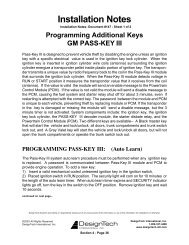
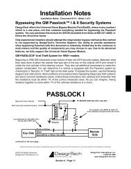
VATS:<br />
Before performing this set up, make sure the vehicle will start with the transmitter<br />
if you leave the ignition key in the key cylinder.<br />
1. Put dip switch 1, 7 and 8 into the OFF (up) position<br />
2. Measure the resistance of the key. It should be between 392 ohms and 11,800<br />
ohms. To do this, put the ohm meter probes on each side of the key pellet. This<br />
value should be close to one of the following (all values in ohms): 392, 523, 681,<br />
887, 1.13K, 1.47K, 1.87K, 3.01K, 3.74K, 4.75K, 6.04K, 7.5K, 9.53K, 11.8K.<br />
3. Locate the closest value which is less than your desired value on the chart on<br />
page 8. Set dip-switches 2 through 6 as shown on page 8.<br />
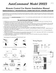
4. Put your ohm meter (multi-meter) probes on the two silver resistance measuring<br />
pads through the opening shown in the drawing -- making good contact with<br />
these two silver pads on the board. (See drawing on page 1). Or put your two<br />
probes into the two holes on the bottom of the case making contact with the<br />
underside of the silver pads. Either contact point method will work.<br />
5. With the probes held firmly, finish reaching the final resistance value needed<br />
for your system by turning the screw on the variable resistor on the side of the<br />
unit next to the dip switches. Turn the screw until the resistance value matches<br />
the resistance value of the key.<br />
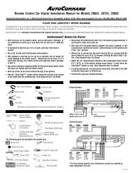
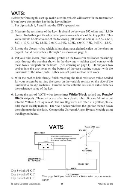
6. Locate the pair of VATS wires (sometimes White/Black striped and Purple/<br />
Black striped). These wires are often in a plastic tube. Be careful not to cut<br />
into the Yellow Air Bag wires! The Air Bag wires are often in a yellow plastic<br />
tube that is clearly marked. The VATS wires run from the ignition switch down<br />
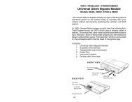
the column under the dash. Connect the Universal Alarm Bypass Module using<br />
the diagram below.<br />
Dip Switch #1 Off<br />
Dip Switch #7 Off<br />
Dip Switch #8 Off<br />
White/Green to Status wire<br />
*See page 16 if you do not have a Status wire on your remote<br />
starter<br />
© 2006 Directed Electronics N20402 08-06