passlock 1 - Ready Remote
passlock 1 - Ready Remote
passlock 1 - Ready Remote

Create successful ePaper yourself
Turn your PDF publications into a flip-book with our unique Google optimized e-Paper software.
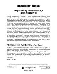
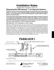
PASSLOCK 1:<br />
1. Put dip switches 1 and 7 in the ON (down) position and dip switch 8 in the OFF<br />
(up) position.<br />
2. Remove the bottom half of the steering column shroud.<br />
3. Locate the small three wire harness (with White, Black and Yellow wires)<br />
running down from the ignition key cylinder on the top right hand side of the<br />
steering column into the instrument panel. These wires are usually the smallest<br />
wires in the harness.<br />
4. Cut the Yellow wire in half and strip back both ends. Remove some of the<br />
insulation on the Black wire without cutting the wire. The White wire is not<br />
used.<br />
5. Turn the ignition key to the “ON” or “RUN” position and place the vehicle into<br />
reverse.<br />
6. With the ignition key still in and turned to the “RUN” position, measure the<br />
resistance between the key side of the Yellow wire (connected to the + positive<br />
lead of your digital meter) and the Black wire (connected to the - negative side<br />
of your digital meter).<br />
7. Turn the ignition key to the “START” position and release it. Denote the<br />
resistance reading as this will be the resistance that will need to be duplicated.<br />
Repeat this step several times to verify that you have a consistent reading.<br />
8. When you have identified the correct resistance use the chart on page 8 to set<br />
the resistance on the bypass module. Locate the closest value which is less than<br />
your desired value. Set dip-switches 2 through 6 to match the chart on page 8<br />
for this value.<br />
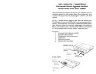
9. Put your ohm meter (multi-meter) probes on the two silver resistance measuring<br />
pads through the opening shown in the drawing -- making good contact with<br />
these two silver pads on the board. (See drawing on page 1). Or put your two<br />
probes into the two holes on the bottom of the case making contact with the<br />
underside of the silver pads. Either contact point method will work.<br />
10. With the probes held firmly -- dial-in the final resistance value needed for your<br />
system by turning the screw on the variable resistor on the side of the unit<br />
next to the dip switches. Turn the screw until the resistance value matches the<br />
resistance value of the key.<br />
11. Locate the Black “Bulb Test” wire on the left side of the steering column in<br />
cavity “D” or “E” of the Black 5-way connector, just above the main ignition<br />
switch connector. This is a different wire than the Black wire mentioned in<br />
the above steps.<br />
12. Connect the bypass module using the diagram below. Be sure to tape over any<br />
connections to not leave any exposed wires.<br />
N20402 08-06 0 © 2006 Directed Electronics