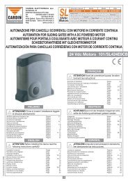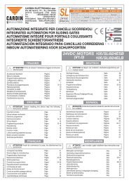
1 - Cardin Elettronica
1 - Cardin Elettronica
1 - Cardin Elettronica

Create successful ePaper yourself
Turn your PDF publications into a flip-book with our unique Google optimized e-Paper software.
IMPORTANT REMARKS IMPORTANT REMARKS IMPORTANT REMARKS<br />
READ THE FOLLOWING REMARKS CAREFULLY BEFORE PROCEEDING WITH THE INSTALLATION.<br />
PAY PARTICULAR ATTENTION TO ALL THE PARAGRAPHS MARKED WITH THE SYMBOL . NOT READING THESE<br />
IMPORTANT INSTRUCTIONS COULD COMPROMISE THE CORRECT WORKING ORDER OF THE SYSTEM AND CREATE<br />
DANGER SITUATIONS FOR THE USERS OF THE SYSTEM. SAVE THESE INSTRUCTIONS FOR FUTURE USE.<br />
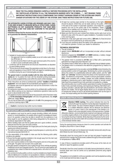
THE INTEGRATED CARDIN SYSTEMS ARE DESIGNED AND BUILT ONLY<br />
TO BE USED IN MADE TO MEASURE METALLIC STRUCTURES. CARDIN<br />
ELETTRONICA DO NOT GUARANTEE PRODUCTS THAT HAVE BEEN<br />
INSTALLED IN A WAY THAT DOES NOT CONFORM TO THE SUPPLIED<br />
INDICATIONS.<br />
It therefore follows that the structure should be constructed in such a way<br />
as to guarantee the following characteristics:<br />
A<br />
B<br />
• Suitable for housing electronic appliances:<br />
- the upper part must be completely sealed, so as not to allow water infiltration<br />
(IP55) (det. A);<br />
- Air vents should be fitted in both the upper and lower parts of the columns<br />
in order to avoid condensate build up (det. B);<br />
• Conformity with the dimensional and structural characteristics as stipulated<br />
by good building practice<br />
• The end structure should respect the parameters as laid down by the standards<br />
and regulations in force UNI EN 12453 with regard to maintaining safety<br />
conditions during the use of motorized gates and doors.<br />
The geared motor is normally installed with the drive shaft pointing upwards<br />
(det. A). To position the motor with the driveshaft pointing downwards<br />
(det. C) create a supplementary cover within the column where necessary.<br />
• These instructions are aimed at professionally qualified "installers of electrical<br />
equipment" and must respect the local standards and regulations in force.<br />
All materials used must be approved and must suit the environment in which the<br />
installation is situated.<br />
• All maintenance operations must be carried out by professionally qualified technicians.<br />
Before carrying out any cleaning or maintenance operations make sure the<br />
power is disconnected at the mains.<br />
• This appliance must be used exclusively for the purpose for which it has been made.<br />
"i.e. for the automation of hinged gates" with one or two gate leaves, max. length<br />
1,8 m max. weight 150 kg.<br />
The unit may be fitted both to the right and to the left of the passageway and has<br />
a maximum opening angle of 180°.<br />
Caution! a mechanical stop buffer must be installed.<br />
IMPORTANT SAFETY INSTRUCTIONS<br />
• This appliance must never be used by people (including children) with physical,<br />
sensory or mental disabilities or by people without specific knowledge and experience<br />
in its operation unless they are able to benefit from the experience or are<br />
being taught to use the appliance whilst being safeguarded by the presence of<br />
somebody responsible for their safety.<br />
• Before installing make sure that the guided parts are in good condition, correctly<br />
balanced and that they open and close correctly.<br />
• Avoid becoming trapped between the hinged parts and the fixed parts during the<br />
opening and closing movements.<br />
• The motor’s power cable must be made of polychloroprene in conformity with the<br />
international standard 60245 IEC 57.<br />
It is the responsibility of the installer to make sure that the following public safety<br />
conditions are satisfied:<br />
1) Ensure that the gate operating installation is far enough away from the main road<br />
to eliminate possible traffic disruptions.<br />
2) The motor must be installed on the inside of the property and not on the public side<br />
of the gate. The gates must not open onto a public area.<br />
3) The gate operator is designed for use on gates through which vehicles are passing.<br />
Pedestrians should use a separate entrance. The unit cannot be used together with<br />
a pedestrian door unless it is fitted with a separate device with which to control the<br />
pedestrian door.<br />
4) The controls (including safety controls ) must be installed at a height between<br />
1,5 and 1,8 m and in a location not accessible to children. Controls installed<br />
externally must be protected by a safety device inhibiting unauthorised use.<br />
C<br />
12<br />
5) At least two warning signs (similar to the example on the right)<br />
should be placed, where they can be easily seen by the public,<br />
in the area of the system of automatic operation. One inside the<br />
property and one on the public side of the installation. These<br />
signs must be indelible and not hidden by any objects (such as<br />
tree branches, decorative fencing etc.).<br />
6) Make sure that the end-user is aware that children and/or pets must not be<br />
allowed to play within the area of a gate installation. If possible include this<br />
in the warning signs.<br />
7) Whenever a fully open gate leaf comes within ≤ 500 mm of a fixed structure<br />
the space must be protected by an anticrush buffer.<br />
8) If you have any questions about the safety of the gate operating system, do<br />
not install the operator. Contact your dealer for assistance.<br />
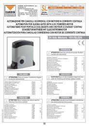
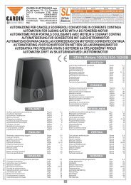
TECHNICAL DESCRIPTION<br />
• The set consists of:<br />
2 geared motors 200/BLi824 with an incorporated encoder without onboard<br />
electronics;<br />
1 electronic programmer CC242EINT with NiMH batteries, a battery charger<br />
and an integrated S449 radio frequency module.<br />
• The geared motor is powered by 24 Vdc and is fitted with a permanently<br />
lubricated four-stage epicycloid reduction unit.<br />
• The geared motor is fitted with an Allen key operated manual release system.<br />
• The geared motor is connected to the electronic programmer by means of a<br />
6 wire cable.<br />
• Electronic programmer for two encoder-controlled 24 Vdc motors that allow the<br />
precise position control of hinged gates. Monitoring the current consumption<br />
allows the control of a sophisticated anticrush safety system, and the "soft<br />
start" and "soft stop" functions reduce the stress on the mechanical components.<br />
The electronic components , housed in a shock-proof plastic container<br />
IP55, come complete with a battery charger and buffer batteries allowing<br />
emergency manoeuvring and a radio frequency module for remote control.<br />
Gate travel time programming is fully automatic and guided by a display.<br />
Dip-switches allow you to set the system parameters including: the sequential<br />
button mode, automatic reclosing, warning lamp pre-flashing, intermittent warning<br />
lamp activation, indicator light and photoelectric cell function setting and<br />
electric lock enable. The six figure display allows you to visualise the number<br />
of manoeuvres carried out and to set several parameters such as the type of<br />
motor, the torque setting and the limited opening distance.<br />
USER INSTRUCTIONS<br />
WARNING<br />
AUTOMATIC OPENING<br />
KEEP CLEAR<br />
CHILDREN OR PETS MUST NOT<br />
BE ALLOWED TO PLAY ON OR<br />
NEAR THE INSTALLATION<br />
Attention! WEEE marking. This symbol indicates that once the<br />
products life-span has expired it must be disposed of separately from<br />
other rubbish. The user is therefore obliged to either take the product<br />
to a suitable differential collection site for electronic and electrical<br />
goods or to send it back to the manufacturer if the intention is to<br />
replace it with a new equivalent version of the same product. Suitable<br />
differential collection, environmental friendly treatment and disposal contributes<br />
to avoiding negative effects on the ambient and consequently health as well as<br />
favouring the recycling of materials. Illicitly disposing of this product by the owner<br />
is punishable by law and will be dealt with according to the laws and standards<br />
of the individual member nation.<br />
During the opening/closing manoeuvre check for correct operation and activate the<br />
emergency stop button in case of danger.<br />
During blackouts the gate can be released and manually manoeuvred using the supplied<br />
release key (see manual release pag. 13).<br />
Periodically check the moving parts for wear and tear and grease if required using<br />
lubricants which maintain their friction levels unaltered throughout time and are suitable<br />
for temperatures of -20 to +70°C.<br />
In case of failure or operational anomalies switch off the power at the mains do not<br />
attempt to repair the appliance yourself.<br />
Periodically check the correct operation of all safety devices (photoelectric cells etc.).<br />
Eventual repair work must be carried out by specialised personnel using original<br />
spare parts.<br />
The appliance is not suitable for continuous operation and must be adjusted according<br />
to the model (see technical data on page 48).