1 - Cardin Elettronica
1 - Cardin Elettronica
1 - Cardin Elettronica

Create successful ePaper yourself
Turn your PDF publications into a flip-book with our unique Google optimized e-Paper software.
INSTRUCTIONS FOR USE<br />
• This device has been created to be integrated into the structure of specially made<br />
hinged gates. The geared motor is fitted with screw type attachments that allow it<br />
to be fitted inside metal profiles.<br />
• The drive shaft can accommodate transmission brackets and adjustable articulated<br />
joints. The device is extremely compact and allows it to be integrated either into the<br />
gate's upright or into the gate support column.<br />
Note: If you build the motor into the gate support column, the movement generated<br />
by the propulsion unit will have to be transmitted to the gate leaf by a pinion or pulley<br />
that is protected by an external case.<br />
• The propulsion unit can be fitted either to the upper part or to the lower part of the<br />
upright using the geared motor in both senses of rotation.<br />
• When building the motor into the gate leaf the axis of rotation must correspond to<br />
that of the gate hinge.<br />
ASSEMBLY PROCEDURE<br />
The unit may be positioned either to the right or to the left of the passageway:<br />
• Respect the following limits:<br />
- maximum gate weight per leaf is 150 kg;<br />
- maximum gate length is 1,8 m;<br />
The builder must make sure that the closing system respects the technical indications<br />
supplied by the standards and laws in force:<br />
- Opening and closing direction mechanical stops;<br />
- Safety margins;<br />
- Correct risk analysis at possible crushing points etc.<br />
See: www.cardin.it - archive - installation and certification guide.<br />
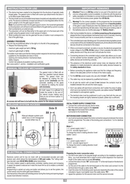
MANUAL RELEASE MECHANISM<br />
The geared motor is fitted with an<br />
Allen key operated manual release<br />
system. The geared motor can<br />
be released by rotating the hexagonal<br />
socket clockwise and the<br />
automatic resetting of the gears<br />
is obtained by rotating the socket<br />
anti-clockwise.<br />
In both cases it is sufficient to<br />
rotate the socket to the end of<br />
its natural course making sure<br />
that you do not force it (about 12<br />
rotations).<br />
An access slot will have to be built into the column for the release mechanism.<br />
RELEASE SYSTEM ACCESS<br />
Side A<br />
33<br />
Manual release system activated<br />
via a 3 mm hexagonal<br />
socket (Allen key 3)<br />
33<br />
Side B<br />
IMPORTANT REMARKS<br />
Attention! There is no 230 Vac contact on any part of the electronic card:<br />
only low voltage safety current is available. In conformity with the electrical<br />
safety standards it is forbidden to connect binding posts 9 and 10 directly<br />
to a circuit that receives power greater than 30 Vac/dc.<br />
Warning! For the correct operation of the programmer the incorporated<br />
batteries must be in good condition: the programmer will lose the position<br />
of the gate in case of blackouts when the batteries are flat, the alarm will<br />
sound and repositioning will take place. Check the good working order of<br />
the batteries every six months (see page 18 "Battery check").<br />
• After having installed the device, and before powering up the programmer,<br />
release the door (manual release mechanism) and move it manually, checking<br />
that it moves smoothly and has no unusual points of resistance.<br />
• The controlled load output (binding post 15) is aimed at reducing battery power<br />
consumption (if they are installed) during blackouts; photocells and other safety<br />
devices should be connected to this output.<br />
• When a command is received, via radio or via wire, the electronic programmer<br />
routes voltage to the CTRL 30 Vdc output. It then evaluates the state of the<br />
safety devices and if they are at rest it will activate the motor.<br />
• Connecting devices to the controlled output contact also allows you to carry<br />
out the autotest function (enabled using DIPs 7 and 8) and check that the<br />
safety devices are functioning correctly.<br />
• The presence of the electrical current sensor does not dispense with the<br />
obligation to install photoelectric cells and other safety devices foreseen by<br />
the safety standards in force.<br />
• Before connecting the appliance make sure that the voltage and frequency<br />
rated on the data plate conform to those of the mains supply.<br />
• For the 230 Vac power supply only use a 2 x 1.5 mm 2 + cable.<br />
• The cable may only be replaced by qualified technicians.<br />
• An all pole trip switch with at least 3 mm between the contacts must be<br />
installed between the unit and the mains supply.<br />
• Don't use cables with aluminium conductors; don't solder the ends of cables<br />
which are to be inserted into the binding posts; use cables marked T min 85°C<br />
and resistant to atmospheric agents.<br />
• The terminal wires must be positioned in such a way that both the wire and<br />
the insulating sheath are tightly fastened (a plastic jubilee clip is sufficient).<br />
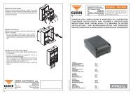
230 Vac POWER SUPPLY CONNECTION<br />
• Connect the control and security device wires.<br />
• Run the mains power supply to the separate<br />
two-way terminal board that is already<br />
connected to the transformer.<br />
MOTOR/ENCODER CONNECTION<br />
• you must scrupulously respect the motor connection sequence between the motors<br />
and the programmer. The order of the binding post connections 1 to 6 is identical<br />
on both;<br />
N<br />
L<br />
115<br />
3<br />
109<br />
Motor 1<br />
1- 2 - power supply motor 1<br />
3-4-5-6 - encoder signal input 1<br />
To change the motor's rotating direction invert<br />
cables 1 and 2<br />
Motor 2<br />
1- 2 - power supply motor 2<br />
3-4-5-6 - encoder signal input 2<br />
To change the motor's rotating direction invert<br />
cables 1 and 2<br />
PC<br />
M1 ENCODER 1<br />
Bl Gr Gy Yw<br />
1 2<br />
3 4 5 6<br />
ELECTRICAL CONNECTION<br />
Electronic control unit for two dc motor with an incorporated encoder and radio<br />
receiver card, which allows the memorisation of 300 user codes. The "rolling code"<br />
type decoder uses 433.92 MHz (S449) series transmitters.<br />
The motor rotation speed is electronically controlled, starting slowly and increasing<br />
in speed; the speed is reduced as it nears the travel limit so as to enable a controlled<br />
smooth stop.<br />
Programming is carried out using one button and allows you to set the system, the<br />
current sensor and the entire gate travel distance.<br />
The intervention of the anticrush/antidrag sensor during the closing and opening stages<br />
causes travel direction inversion.<br />
Preparing the motor connection wires<br />
• Cut the 6-wire cable to the required length according to the installation specifications;<br />
you must remember that in order to avoid current dispersion the maximum<br />
length of the cable must not exceed 20 metres.<br />
• connect the wires of motor "M1" and encoder "1" to the main board on the electronic<br />
programmer;<br />
• run the end of the cable to the terminal board on the motor and connect it to the<br />
terminal block through a cable clamp "PC".<br />
• insert the wires into the binding posts rigorously respecting the order of the colours<br />
indicated in figure 4 and tighten down the cable clamp "PC";<br />
• repeat the operation for the second motor and the second encoder.<br />
13