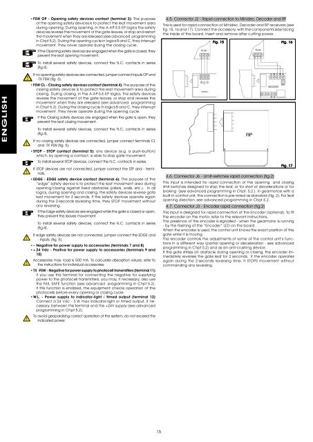
ENGLISH• FSW OP - Opening safety devices contact (terminal 3): The purposeof the opening safety devices is to protect the leaf movement areaduring opening. During opening, in the A-AP-S-E-EP logics the safetydevices reverse the movement of the gate leaves, or stop and restartthe movement when they are released (see advanced programmingin Chpt 5.2). During the opening cycle in logics B and C, they interruptmovement. They never operate during the closing cycle.If the Opening safety devices are engaged when the gate is closed, theyprevent the leaf opening movement.To install several safety devices, connect the N.C. contacts in series(fig.4).If no opening safety devices are connected, jumper connect inputs OP and-TX FSW (fig. 5).• FSW CL - Closing safety devices contact (terminal 4): The purpose of theclosing safety devices is to protect the leaf movement area duringclosing. During closing, in the A-AP-S-E-EP logics, the safety devicesreverse the movement of the gate leaves, or stop and reverse themovement when they are released (see advanced programmingin Chpt 5.2). During the closing cycle in logics B and C, they interruptmovement. They never operate during the opening cycle.If the Closing safety devices are engaged when the gate is open, theyprevent the leaf closing movement.To install several safety devices, connect the N.C. contacts in series(fig.4).If no closing safety devices are connected, jumper connect terminals CLand -TX FSW (fig. 5).• STOP - STOP contact (terminal 5): any device (e.g. a push-button)which, by opening a contact, is able to stop gate movement.To install several STOP devices, connect the N.C. contacts in series.If STOP devices are not connected, jumper connect the STP and - terminals.• EDGE - EDGE safety device contact (terminal 6): The purpose of the“edge” safety device is to protect the leaf movement area duringopening/closing against fixed obstacles (pillars, walls, etc.). In alllogics, during opening and closing, the safety devices reverse gateleaf movement for 2 seconds. If the safety devices operate againduring the 2-seconds reversing time, they STOP movement withoutany reversing.If the Edge safety devices are engaged while the gate is closed or open,they prevent the leaves movement.To install several safety devices, connect the N.C. contacts in series(fig.4).If edge safety devices are not connected, jumper connect the EDGE and- inputs. (fig. 5).• – Negative for power supply to accessories (terminals 7 and 8)• + 24 Vdc - Positive for power supply to accessories (terminals 9 and10)Accessories max. load is 500 mA. To calculate absorption values, refer tothe instructions for individual accessories.• TX -FSW - Negative for power supply to photocell transmitters (terminal 11)If you use this terminal for connecting the negative for supplyingpower to the photocell transmitters, you may, if necessary, also usethe FAIL SAFE function (see advanced programming in Chpt 5.2).If this function is enabled, the equipment checks operation of thephotocells before every opening or closing cycle.• W.L. - Power supply to indicator-light / timed output (terminal 12)Connect a 24 Vdc - 3 W max indicator-light or timed output, if necessary,between this terminal and the +24V supply (see advancedprogramming in Chpt 5.2).To avoid geopardising correct operation of the system, do not exceed theindicated power.4.5. Connector J2 - Rapid connection to Minidec, Decoder and RPThis is used for rapid connection of Minidec, Decoder and RP receivers (seefig. 15, 16 and 17). Connect the accessory, with the components side facingthe inside of the board. Insert and remove after cutting power.Fig. 15 Fig. 16Fig. 174.6. Connector J6 - Limit-switches rapid connection (fig.2)This input is intended for rapid connection of the opening and closinglimit-switches designed to stop the leaf, or for start of decelerations or forbraking (see advanced programming in Chpt. 5.2.). In gearmotors with abuilt-in control unit, this connection is pre-wired as standard (fig. 2). For leafopening direction, see advanced programming in Chpt 5.2.4.7. Connector J3 - Encoder rapid connection (fig.2)This input is designed for rapid connection of the Encoder (optional). To fitthe encoder on the motor, refer to the relevant instructions.The presence of the encoder is signalled - when the gearmotor is running- by the flashing of the “Encoder” LED on the board.When the encoder is used, the control unit knows the exact position of thegate while it is moving.The encoder controls the adjustments of some of the control unit’s functionsin a different way (partial opening or deceleration - see advancedprogramming in Chpt 5.2) and as an anti-crushing device.If the gate strikes an obstacle during opening or closing, the encoder immediatelyreverses the gate leaf for 2 seconds. If the encoder operatesagain during the 2-seconds reversing time, it STOPS movement withoutcommanding any reversing.15
5. PROGRAMMINGTo program operation of the automated system, you have to access the“PROGRAMMING” mode.Programming is split into two parts: BASIC and ADVANCED.5.1. BASIC PROGRAMMINGTo access BASIC PROGRAMMING, press key F:• if you press it (and hold it down), the display shows the name of the firstfunction.• if you release the key, the display shows the value of the function that canbe modified with keys + and -.• if you press F again (and hold it down), the display shows the name ofthe next function, etc.• when you reach the last function, press F to exit the program, and thedisplay resumes showing the gate status.The following table shows the sequence of functions accessible in BASICPROGRAMMING:BASIC PROGRAMMINGDisplay Function DefaultLOFUNCTION LOGICS (see tab. 3/a - h):A =AutomaticAP =“Stepped” automaticS = “Safety” AutomaticE = Semi-automaticEP = “Stepped” Semi-automaticC = Dead-manEP= “B” Semi-automaticPAF0d1StbbC = Mixed Log. (b opening / C closing)PAUSE TIME:This has effect only if the automatic logic wasselected. Adjustable from 0 to 59 sec. in onesecondsteps.Subsequently, display changes to minutes andtens of seconds (separated by a point) and timeis adjusted in 10-second steps, up to the maximumvalue of 4.1 minutes.E.g. if the display shows 2.5, pause time is 2 min.and 50 sec.FORCE:Adjusts Motor thrust.01 = minimum force50 = maximum forceOPENING DIRECTION:Indicates the gate opening movement andmakes it possible not to change the motor andlimit-switch connections on the terminal board.-3 = Right-hand opening movementE- = Left-hand opening movementGATE STATUS:Exit from programming and return to gate statusviewing.00 = Closed01 = Now opening02 = Stopped03 = Open04 = Pause05 = “FAIL SAFE” tripped (chpt. 5.2)06 = Now closing07 = Now reversing08 = Photocells trippedF2.050-35.2. ADVANCED PROGRAMMINGTo access ADVANCED PROGRAMMING, press key F and, as you hold itdown, press key +:• if you release key + , the display indicates the name of the first function.• if you release key F too, the display shows the value of the function thatcan be modified with keys + and -.• if you press key F (and hold it down), the display shows the name of thenext function, and if you release it, the value that can be modified withkeys + and - is shown.• when you reach the last function, press F to exit the program, and thedisplay resumes showing the gate status.The following table shows the sequence of functions accessible in ADVAN-CED PROGRAMMING:ADVANCED PROGRAMMING F + +Display Function Defaultb0MAXIMUM TORQUE AT INITIAL THRUST:The motor operate at maximum torque (ignoringthe torque setting) at start of movement. Usefulfor heavy leaves.Y = Activeno = DisabledYADVANCED PROGRAMMING F + +Display Function DefaultbrFSPFSPPhoPFINAL BRAKING:When the gate engages the opening or closinglimit-switch, a braking stroke can be selectedto ensure the leaf is stopped immediately. Ifdecelerations are selected, braking starts whenthey finish.At 00 value, braking is disabled.Time can be adjusted from 01 to 20 sec. in 0.1-second steps.E.g. if the display indicates 10, braking time is 1second.00 = Braking disabledfrom 01 to 20 = Timed brakingFAIL SAFE:If this function is activated, it enables a functiontest of the photocells before any gate movement.If the test fails (photocells not serviceable signalledby value 05 on the display), the gate doesnot start moving.Y = Activeno = DisabledPRE-FLASHING (5 s):Activates the flashing lamp for 5 seconds beforestart of movement.no = DisabledoP = Only before openingCL = Only before closingOC = Before every movementINDICATOR-LIGHT:If 00 is selected, the output functions as a standardindicator-light (lighted at opening andpause, flashing at closing, and off when gateclosed).Courtesy light: Different figures correspond to timedactivation of the output, which can be used(by a relay) to power a courtesy lamp. Time canbe adjusted from 0 to 59 sec. in 1-second steps,and from 1.0 to 4.1 min. in 10-second steps.Electric lock command and ‘traffic lights’ functions:If you press key - from the 00 setting, thecommand for the E1 closing electric lock isactivated;If you press - again, the command for the E2closing and opening electric lock is set;if you press the - key again, you can set the‘traffic lights’ functions E3 and E4.00 = Standard indicator-lightfrom 01 to 4.1 = Timed output.E1 = electric lock command before openingmovementE2 = electric lock command before opening andclosing movementsE3 = ‘traffic lights’ function: the output is activein “open” and “open on pause” status and isdisabled 3 seconds before the closing manoeuvrestarts.there is 3 seconds of pre-flashing before theclosing manoeuvre.E4 = ‘traffic lights’ function: the output is activeonly in “closed” status.Do not exceed the output’s maximum load(24Vdc-3W). If necessary, use a relayand a power supply source outside theequipment.CLOSING PHOTOCELLS LOGIC:Select the tripping mode of the closing photocells.They operate for the closing movement only: theystop movement and reverse it when they arereleased, or they reverse it immediately.Y = Reverse on releaseno = Reverse immediately when openingOPENING PHOTOCELLS LOGIC:Select the tripping mode of the opening photocells.They operate for the opening movement only:they stop the movement and restart it when theyare released, or they reverse it immediately.Y = Reverse immediately when closingno = Restart movement on release05nono00nonoENGLISH16