41884. Installazione IS 12-14-16-19.p65 - Mase Generators of North ...
41884. Installazione IS 12-14-16-19.p65 - Mase Generators of North ...
41884. Installazione IS 12-14-16-19.p65 - Mase Generators of North ...
- No tags were found...

You also want an ePaper? Increase the reach of your titles
YUMPU automatically turns print PDFs into web optimized ePapers that Google loves.
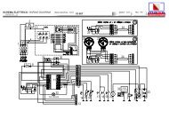
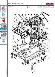
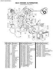
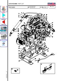
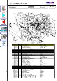
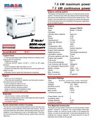
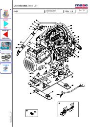
GENERATORSGB<strong>IS</strong> <strong>12</strong>-<strong>14</strong>-<strong>16</strong>-196.4. Generator - Mains switchingA switch should be placed on the line to switch the userappliances from the generator to an external power line.The switch should be dimensioned according to the size<strong>of</strong> the loads: a general diagram is shown in fig.18.7 HANDLINGFor handling and lifting <strong>of</strong> the generator only use the liftinghook located on the engine.Hooking the generator at points different from thatindicated may cause damage to the generator or bedangerous to the operators.8 WIRING DIAGRAM REFERENCESSee Fig.191 - Magnetothermal switch2 - Hour counter3 - Alternator4 - Rotor5 - Stator6 - Voltage regulator7 - Power terminal board8 - Insulators9 - Thermal switch10 - START / STOP- button11 - Engine protection module<strong>12</strong> - Terminal board13 - Connector for remote control panel connection<strong>14</strong> - Fuel level gauge15 - Oil pressure gauge<strong>16</strong> - Water temperature gauge17 - High water temperature sensor18 - High coolant temperature sensor19 - Oil pressure switch20 - Battery charger alternator21 - Stop electromagnet22 - Starter motor23 - Battery connection terminals24 - Panel connection cable25 - START / STOP- button26 - Oil pressure gauge instrument27 - Coolant temperature gauge instrument28 - Remote control panel kit with instruments29 - Remote control panel kit- 21 -