41964 MAN INSTALIS3.5-5.0.p65 - Mase Generators of North America
41964 MAN INSTALIS3.5-5.0.p65 - Mase Generators of North America
41964 MAN INSTALIS3.5-5.0.p65 - Mase Generators of North America
- No tags were found...

You also want an ePaper? Increase the reach of your titles
YUMPU automatically turns print PDFs into web optimized ePapers that Google loves.
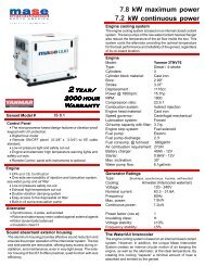
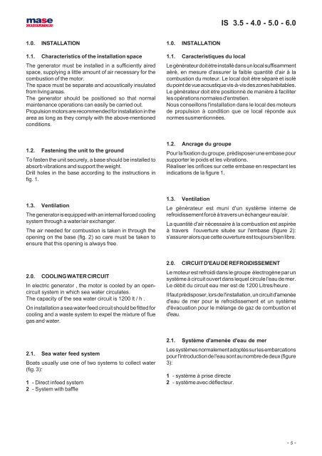
IS 3.5 - 4.0 - 5.0 - 6.01.0. INSTALLATION1.1. Characteristics <strong>of</strong> the installation spaceThe generator must be installed in a sufficiently airedspace, supplying a little amount <strong>of</strong> air necessary for thecombustion <strong>of</strong> the motor.The space must be separate and acoustically insulatedfrom living areas.The generator should be positioned so that normalmaintenance operations can easily be carried out.Propulsion motors are recommended for installation in thearea as long as they comply with the above-mentionedconditions.1.0. INSTALLATION1.1. Caracteristiques du localLe gènèrateur doit ètre installè dans un local suffisammentaèrè, en mesure d'assurer la faible quantitè d'air à lacombustion du moteur. Le local doit ètre sèparè et isolèdu point de vue acoustique vis-à-vis des zones habitables.Le gènèrateur doit ètre positionnè de manière à faciliterles opèrations normales d'entretien.Nous conseillons l'installation dans le local des moteursde propulsion à condition que ce local rèponde auxnormes susmentionnèes.1.2. Fastening the unit to the groundTo fasten the unit securely, a base should be installed toabsorb vibrations and support the weight.Drill holes in the base according to the instructions infig. 1.1.2. Ancrage du groupePour la fixation du groupe, prèdisposer une embase poursupporter le poids et les vibrations.Rèaliser les orifices sur cette embase en respectant lesindications de la figure 1.1.3. VentilationThe generator is equipped with an internal forced coolingsystem through a water/air exchanger.The air needed for combustion is taken in through theopening on the base (fig. 2) so care must be taken toensure that this opening is always free.1.3. VentilationLe gènèrateur est muni d'un système interne derefroidissement forcè à travers un èchangeur eau/air.La quantitè d'air nècessaire à la combustion est aspirèeà travers l'ouverture situèe sur l'embase (figure 2):s'assurer alors que cette ouverture est toujours bien libre.2.0. COOLING WATER CIRCUITIn electric generator , the motor is cooled by an opencircuitsystem in which sea water circulates.The capacity <strong>of</strong> the sea water circuit is 1200 lt / h .On installation a sea water feed circuit should be fitted forcooling and a waste system to expel the mixture <strong>of</strong> fluegas and water.2.0. CIRCUIT D'EAU DE REFROIDISSEMENTLe moteur est refroidi dans le groupe èlectrogène par unsystème à circuit ouvert dans lequel circule l'eau de mer.Le dèbit du circuit eau mer est de 1200 Litres/heure .Il faut prèdisposer, lors de l'installation, un circuit d'amenèed'eau de mer pour le refroidissement et un systèmed'èvacuation pour le mèlange de gaz de combustion etd'eau.2.1. Sea water feed systemBoats usually use one <strong>of</strong> two systems to collect water(fig. 3):1 - Direct infeed system2 - System with baffle2.1. Système d'amenèe d'eau de merLes systèmes normalement adoptès sur les embarcationspour l'introduction de l'eau sont au nombre de deux (figure3):1 - système à prise directe2 - système avec dèflecteur.- 5 -