USER MANUAL English Français Español - Mcarterbrown.com
USER MANUAL English Français Español - Mcarterbrown.com
USER MANUAL English Français Español - Mcarterbrown.com

Create successful ePaper yourself
Turn your PDF publications into a flip-book with our unique Google optimized e-Paper software.
<strong>USER</strong> <strong>MANUAL</strong><strong>English</strong>FrançaisEspañol
<strong>English</strong>.68 Caliber Semi Automatic Paintball MarkerTABLE OF CONTENTSIMPORTANT SAFETY GUIDELINES 1OPERATION GUIDE / START UP 2CO2 / COMPRESSED AIR TANK WARNINGS 3INSTALLING / REMOVING / CO2 / COMPRESSED AIR TANK 3-4PROPER USE OF BARREL BLOCKING DEVICE 4VELOCITY ADJUSTMENT INCREASE / DECREASE 4-5A JAMMED PAINTBALL 5QUICK CLEAN / DISASSEMBLE / REASSEMBLE REAR INTERNALS 5-6CUP SEAL REMOVAL GUIDE 7AIR LEAK 8TROUBLESHOOTING 9SONIX PARTS LIST 10SONIX SCHEMATIC 11WARRANTY STATEMENT 12
IMPORTANT SAFETY GUIDELINESWARNING• This paintball marker is NOT a toy. It can cause serious injury or death.• Kingman re<strong>com</strong>mends that the customer be at least 18 years of age to purchase this product.• Read this manual and air tank warnings before using this product.• Any modifications or tampering of original factory parts will void all warranties and liabilitiesfrom Kingman.• Kingman re<strong>com</strong>mends using a barrel blocking device when the marker is not in operation.• To ensure proper adjustment of velocity (fps), Kingman strongly re<strong>com</strong>mends using achronograph for paintball use located at most paintball stores and paintball fields.• Before / after use of the marker, make sure to fasten all screws. Screws may be<strong>com</strong>e loose dueto vibration. Loose screws can be dangerous and cause injury.• Kingman STRONGLY re<strong>com</strong>mends that any person using this product or within range of thisproduct while it is in use MUST wear EYE/FACE PROTECTION designed specifically for thesport of paintball. This includes, but is not limited to, performing a maintenance check and duringtarget practice.• Kingman reminds the user that it is YOUR RESPONSIBILITY to protect your eyes/face at alltimes, and will not be held liable for injuries sustained when failing to wear the appropriateprotection.• Never shoot or point your marker at a person that is not in a designated paintball facility andwithout proper paintball protection.• Treat every paintball marker as if it were loaded.• Never look down the barrel of a loaded or unloaded marker.• Always keep the paintball marker in SAFE or OFF mode until ready to operate.• Always remove the gas source before disassembly.• Fire only 0.68 caliber paintballs with this product.• Always make certain the bolt is in the un-cocked position when marker is not in use.• Using a paintball marker outside of a non designated paintball field can be illegal, and is subjectto law enforcement penalties if property damage is caused by the user.• Never point or shoot your marker at an animal.• Transfer this instruction manual upon change of marker ownership.1
<strong>English</strong>OPERATION GUIDE / START UPWARNING: Always keep the marker powered OFF or on SAFE until you are ready to fire.1.2.3.4.5.6.7.8.9.10.11.12.13.Kingman re<strong>com</strong>mends having the marker in the “SAFE” position before use. To operate, push the safetybutton from the “PUSH SAFE” side of the trigger frame. This will position the marker in a lock safe mode. Todisengage the safety button in a safely manner, point the marker in a safe direction, and push the safety buttontowards the “PUSH FIRE” side of the trigger frame.Place the barrel plug or barrel blocking device over the barrel for safety precaution when the marker is not inuse.Attach the CO2 / Compressed air tank to the C/A Adapter. HELPFUL TIP: Make sure to have the CO2 /Compressed air tank filled before attaching. Tighten the tank clockwise in the markers C/A Adapter until it issnug. If an air leak occurs between the tank and the C/A Adapter, replace with a urethane bottle o-ring. NOTE:O-rings in the markers parts kit are not supplied to attach with a CO2 / Compressed Air Tank. IMPORTANT:You should never need to use any hand tool to attach a CO2 / Compressed Air Tank to the C/A Adapter.Attach the elbow and a paintball loader to the markers feed neck. (* Not Pictured) NOTE: Fill your paintballloader with only .68 caliber paint.Cocking the marker. Pull the Top Cocking Knob (#STK002) rearward until the Delrin Bolt latches. CAUTION:Should you let go of the Top Cocking Knob before it latches, your marker may fire.Remove barrel plug or barrel blocking device over the barrel.CAUTION: With the safety button released in the FIRE position the marker is LIVE. By pulling the trigger(#TRS003) will fire a paintball. IMPORTANT: In a safe direction or in a designated playing field should youonly test the markers capability.Performing a velocity (fps) check. Turning the Velocity Adjuster & Spring Guide (#VTA007 or #VTA0016)clockwise will increase the velocity (fps). Counter-clockwise will decrease the velocity (fps). NOTE: Yourmarker is intended to be used in a paintball facility with the proper paintball protection. IMPORTANT: Kingmanre<strong>com</strong>mends using a chronograph to ensure the marker’s Velocity is under 300 (fps).Detach the paintball loader and all paintballs from the marker. When finished playing remove the paintballloader and vertical elbow from the marker. CAUTION: There may be a paintball in the markers breach; take acouple of shots in a safe direction to make sure the barrel and Receiver are empty.Place the barrel plug or barrel blocking device over the barrel for safety precaution when the marker is not inuse. This will help avoid any accidental discharge.Kingman re<strong>com</strong>mends having the marker in the “SAFE” position after use.Unscrew the CO2 / Compressed air tank from the markers C/A Adapter. By turning the tank counter-clockwisewill detach from the markers C/A Adapter. CAUTION: Never expose any skin underneath the C/A Adaptersbleed hole when removing the tank. This can run the risk of getting skin burn from the releasing of the GAS.IMPORTANT: You should never need to use any hand tool to detach a CO2 / Compressed Air Tank.Store the marker in a paintball bag or in a safe place. HELPFUL TIP: Before / after use of the marker, makesure to fasten all Screws. Screws can be<strong>com</strong>e loss cause of vibration. It’s a good practice to lubricate yourmarker before and after each use, especially when storing the marker for an extended period of time. Add afew drops of paintball gun oil on the Striker O-ring (#ORG001) (SEE DISSEMBLE / REASSEMBLE). Beforestoring the marker, make sure to have the marker in the uncocked position. This way the main spring does notlose its tension.IMPORTANT••••Firing velocity may vary according to altitude and climate conditions.Before using your marker in play, you must always first perform a “SAFE VELOCITY TEST”. This can only beac<strong>com</strong>plished by using a testing device called a “Velocity Chronograph” and can be performed at a paintballdealership or a local playing field. NOTE: This product is intended to be used at a velocity no greater than 300feet per second (FPS). This product is NOT intended to be used at any distance less than 25 feet.This paintball marker may have excess gas after the removal of the CO2 / Compressed air tank. Please removeall paintballs and discharge the remaining gas safely.Never store a CO2 / Compressed air tank attached on the marker while not supervised.2
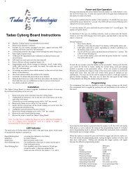
CO2 / COMPRESSED AIR TANK WARNINGSASA007ASA025SAFEWARNING:UNSAFEDANGERThe CO2 or Compressed Air Tank can fly off with enough force to cause seriousinjury or death if the Valve unscrews from the cylinder head. LOOK at the Valvewhen removing the cylinder from the marker. Be sure that the valve is turningwith the cylinder rather than remaining stationary with the marker. STOP if theValve starts to unscrew from the cylinder. If in doubt, screw the cylinder backonto the marker and contact a trained person for repair.CO2 / COMPRESSED AIR TANK WARNINGS• All valves must only be installed or removed by a qualified airsmith.• See CO2 / Compressed Air tank labels for retest dates. Cylinder tanks must be retestedperiodically.• Improper use, filling, storage or disposal of all air cylinders may result in death, personal injuryand/or property damage.• Always keep cylinders out of reach from children or any inexperienced person(s).• Only properly trained personnel in accordance with CGA Pamphlets P.1 and G-6.3 must fill all aircylinders. Pamphlets are available from the Compressed Gas Association or www.CGANET.<strong>com</strong>.• Never alter the cylinder in any way.• DO NOT expose pressurized cylinders to temperatures in excess of 130˚F (54˚C).• Cylinders heated to an excess of 250˚F (121˚C) must be condemned or requalified in accordancewith test defined in CFR-49.• The valve should NEVER be detached from the canister. Please seek immediate assistance from atrained airsmith should this occur.• Any tank packed with the product is intended for paintball use only.• Confirm that there is an attached urethane O-ring on the CO2 / Compressed Air tank valve beforeattaching the tank to the marker. The tank will leak air as soon as it is secured to the marker, if theO-ring is missing from the valve.• A urethane O-ring is highly re<strong>com</strong>mended before attaching any air supply to the marker.• NEVER over pressurize a CO2 / Compressed Air cylinder.• Avoid any direct skin exposure to the escaping gas, when installing or removing any air supply.• Never expose cylinders to corrosive materials or clean with any caustic cleaners.3INSTALLING A CO2 / COMPRESSED AIR TANKFirmly screw the CO2 / Compressed Air Tank clockwise into the markers C/A Adapter (#ASA007 or #ASA025).HELPFUL TIP: Before installing a CO2 / Compressed Air Tank, make sure that the tank is full and that it has aurethane bottle on the top of the valve to prevent air leaks.IMPORTANT: You should never need to use any hand tool to attach a CO2 / Compressed Air Tank to the C/A Adapter.
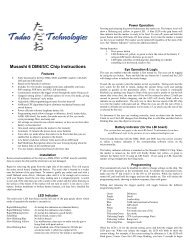
REMOVING A CO2 / COMPRESSED AIR TANKFirmly unscrew the CO2 / Compressed Air Tank by turning the tank counter-clockwise until it <strong>com</strong>es out of the C/AAdapter. HELPFUL TIP: After firing the marker, you should ALWAYS remove the CO2 / Compressed Air Tank beforestoring. When the tank is being removed, excess air will release from the C/A Adapter (#ASA007 or #ASA025)CAUTION: Never expose any skin to the C/A Adapters bleed hole when removing the tank. This is to avoid the risk ofgetting skin burn from the escaping GAS.IMPORTANT: You should never need to use any hand tool to detach a CO2 / Compressed Air Tank from the C/AAdapter. If you cannot remove a tank by hand please see a certified airsmith for assistance.<strong>English</strong>PROPER USE OF YOUR BARREL BLOCKING DEVICEA Barrel Blocking Device or “BBD” is an essential part of your paintball safety equipment. The Barrel Blocking Deviceis designed to stop a paintball from exiting a paintball marker accidentally. Improper use of the Barrel Blocking Devicewill render this device useless.BARREL SOCK/BAG TYPE DEVICEPlace the bag/sock part of the Barrel Blocking Device over the end of your barrel and wrap the elastic cord around theback end of your marker.Adjust the length of the elastic cord to make sure your Barrel Blocking Device fits securely over your markers barrel.NOTE: If the elastic cord is too long you can tie a couple of knots around the cord to shorten its length.BARREL PLUG TYPE DEVICEInsert the barrel plug securely into the end of your markers barrel before proceeding to load paintballs and screwing inyour tank to your marker.The barrel plug should fit firmly into the barrel with a significant amount of resistance. NOTE: The barrel plug shouldnot be easy to remove and always inspect the O-rings to make sure they are not worn or cut.Remove the Barrel Blocking Device only when you are getting ready to begin play or have been instructed to do so bya field safety official.Always keep your Barrel Blocking Device on your marker after you have finished playing. Keep it in placeeven after you have emptied all paintballs and removed your air tank from your paintball marker.WARNING: Inspect your Barrel Block Device regularly for wear and any tear if it is worn, replace it immediately.Always have your Barrel Blocking Device in place on your markers barrel to insure safety and prevent accidents thatmay cause permanent injury or even death.VELOCITY ADJUSTMENT INCREASE / DECREASESTP007STP025Increase VelocityDecrease VelocityVTA007VTA016To INCREASE your velocity FPS (Feet Per Second)using the Allen wrench turn the Velocity Adjuster / SpringGuide (#VTA007 or #VTA016) clockwise.To DECREASE your velocity FPS (Feet Per Second)using the Allen wrench turn the Velocity Adjuster / SpringGuide (#VTA007 or #VTA016) counter-clockwise.4
VELOCITY ADJUSTMENT INCREASE / DECREASE CONT.WARNING•••••The re<strong>com</strong>mended Velocity speed should be no greater then 300 fps. Not doing so can cause serious injury ifthe Velocity is dangerously high.Paintball markers are not intended to shoot any person less then 25 feet.Never point a loaded marker at any person who is not wearing the proper face protection.Never at any point should you look down the barrel, whether the marker is loaded or not.Using a paintball marker outside a non designated paintball field can be illegal, and is subject to lawenforcement penalties if property damage is caused by the user.A JAMMED PAINTBALLIn the event of a paintball break and the Bolt jams, follow these steps to help un-jam the marker. The markersbreach is located where the barrel starts to thread in the Receiver and underneath the markers feed neck. Beforeattempting to un-jam the Bolt you should always have your Goggles or Safety Glasses on. Make sure the marker isin the SAFE / OFF position before attempting to un-jam the Bolt. Remove the CO2 / Compressed Air Tank beforeattempting to un-jam the marker. Remove all paintballs and the loader from the feed neck. Have the barrel removedfrom the Receiver to allow the paintball(s) to exit. With enough force tension on the Top Cocking Knob, pull backto release the Bolt from the jammed position. Another method is to use a “Straight Shot Squeegee” or the end of awood dowel rod; push against the face of the Bolt with enough force to release the jammed Bolt. Always clean thepaint from the breach and barrel to enhance the performance of your marker.IMPORTANT: Never look down the barrel of the marker when loaded or unloaded. Remove the attached CO2 /Compressed Air Tank before attempting to un-jam the Bolt.NOTE: Never use a metal rod or screwdriver as a tool to push on the Bolt, anything metal will scratch and damagethe inside of the marker.QUICK CLEAN & DISASSEMBLE / REASSEMBLE REAR INTERNALSSTK002VTB005STP007STP025STF001STB002SPR004VTA007VTA016RPN0085
<strong>English</strong>Quick Clean DisassembleLift upward on the Top Cocking knob (#STK002). This will allow the Delrin Bolt (#VBT005) sliding from the rearof the Receiver. HELPFUL TIP: With the Delrin Bolt removed out of the Receiver, this allows easy access to cleanwith a squeegee. NOTE: Make sure the hole on the Striker Bolt (#STB002) is facing upright when looking thru theReceiver. This will allow the Top Cocking Knob (#STK002) to correctly fasten with the Striker Bolt. HELPFUL TIP:Please note how the parts are removed for easy reassemblyDisassemble Rear InternalsSTEP 1 Lift upward on the Top Cocking knob (#STK002). This will allow the Delrin Bolt (#VBT005) slide out fromthe rear of the Receiver.STEP 2 Remove the Quick Disconnect Pin (#RPN008). This will allow the Striker Plug (#STP007 or #STP025)and the markers internals to side from the rear of the Receiver. NOTE: Remove the Quick Disconnect Pin when themarkers in the de-cocked position. This way, the tension of the Striker Spring does not allow the markers internalsto spring out. HELPFUL TIP: Placing your finger behind the Striker Plug before removing the Quick Disconnect Pinwill prevent the markers internals to spring out.STEP 3 Remove items in order; Striker Plug (#STP007 or #STP025) w / Velocity Adjuster (#VTA007 or#VTA016), Striker Spring (#SPR004) and Striker Buffer (#STF001).STEP 4 Slide the Striker Bolt (#STB002) out of the rear of the Receiver. HELPFUL TIP: When the internals areremoved it would be wise to clean any dirt or paint from the inside of the Receiver with a squeegee. Wipe clean theDelrin Bolt with a rag or paper towel. Apply some paintball gun on the Striker O-ring periodically.Reassemble Rear InternalsSTEP 1 Insert the Striker Bolt thru the rear of the Receiver with the o-ring facing towards the front of the marker.NOTE: When inserting the Striker Bolt, apply pressure behind the Striker Bolt and at the same time pull on theTrigger (#TRF003) to allow entry of the Striker Bolt. NOTE: The hole on the Striker Bolt should be facing uprightwhen looking thru the Receiver. This will allow the Top Cocking Knob to correctly fasten with the Striker Bolt.STEP 2 Insert the Striker Buffer flush with the Receiver and place the Striker Spring thru the Striker Buffer.STEP 3 Place the Striker Plug w / Velocity Adjuster & Spring Guide to the rear of the Receiver.STEP 4 Insert the Quick Disconnect Pin thru the Receiver to hold the Striker Plug in place.STEP 5 Insert the Delrin Bolt thru the rear of the Receiver with the Top Cocking Knob. Press downward on theTop Cocking Knob to gain entry with the Striker Bolt. NOTE: If the Striker Bolt hole is not aligned upright, the TopCocking Knob will not fasten correctly with the Striker Bolt. HELPFUL TIP: Use a small tool devise to align the holeupright should the Striker Bolt turn when positioned back in the Receiver. IMPORTANT: The Quick Disconnect Pinmust be properly placed thru the Receiver. The ball bearing on the pin must be visible thru the opposite end of theReceiver.To assure marker is assembled properly, follow the schematic drawing or position parts in order during disassembly.Parts assembled backwards or improper parts installed will / can cause the marker to malfunction.WARNINGNever attempt to remove the markers internals while the CO2 / Compressed Air Tank is attached. Make sure toremove all paintballs and loader before disassembling the marker.6
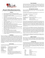
CUP SEAL REMOVALREC023REC025VRT023VRT025ITP012ITP011SPR006ITP013SCR016FRG007FRG025ASA007ASA025SCR019The following steps will provide easy access to the Cup Seal (#ITP012). The sign of a worn out Cup Seal is thepresence of CO2 / Compressed Air leaking down the barrel.STEP 1 Loosen both C/A Adapter Screws (#SCR019) from the C/A Adapter (#ASA007 or #ASA025).STEP 2 Loosen the Vertical Screw M5x12 (#SCR016).STEP 3 Remove the Vertical Adapter (#VRT023 or #VRT025) and Fore Grip Handle (#FRG007 or #FRG025) outthe front of the Receiver (#REC023 or #REC025).STEP 4 Once the Vertical Adapter has been removed the Valve Spring (#SPR006) Valve Pin (#ITP013) Cup SealGuide (#ITP011) and Cup Seal (#ITP012) would be attached with the Vertical Adapter.STEP 5 Detach the Valve Spring from the Vertical Adapter, and then unscrew the Cup Seal from the Valve Pin.Replace the Cup Seal with a new one supplied in the Spare Parts Kit.Once these steps have been <strong>com</strong>pleted, replace the damaged Cup Seal and reassembly all parts back in the Receiver.HELPFUL TIP: Please note how the parts are removed for easy reassembly.CAUTION: Use the proper Allen wrenches to fasten all screws and never apply more force than necessary.IMPORTANT: Always remove the Air Tank before any disassembly of your marker. Do not remove the Valve Body(#ITP014) unless specific Valve Body repairs are needed. Do not remove the Valve Body with a screwdriver as it willdamage the Valve Body Lip and cause air leaks. NOTE: The Valve Body Screw (#SCR015) screw must be removedprior to taking out the Valve Body.7
AIR LEAKIMPORTANT: Always remove the air tank before any disassembling of the marker.••••••Air leaking from the Vertical Adapter means the O-ring (s) (#ORG002) will need to be oiled or replaced.Air leaking down the barrel is usually caused by a worn or damaged Cup Seal (#ITP012). (SEE CUP SEALREMOVAL) should the Cup Seal need to be replaced?Never remove or tamper with the Valve Body (#ITP014) unless specifically repairs are needed.A nick or scratch on the lip of the Valve Body can cause an internal air leak. (SEE CUP SEAL REMOVAL)should the Valve Body need to be replaced?Air leaking thru the Receiver and out of the Trigger Frame would indicate the Valve Body O-ring (s)(#ORG002) will need to be replaced.<strong>English</strong>Air leaking thru the opposite end of the hose fittings please check the following. The Female end of theHose must have a plastic washer (#HSF004) installed inside the hose collar and be tightened properly. TheMale end of the Hose must have a hose o-ring (#ORG004) at the end of the male side of the hose at alltimes.IMPORTANT: The hose line supplied has a Metric Female and Metric Male ends. This will not install into American(NPT) threaded fittings. If installed incorrectly it’s possible to damage the entire attachment fittings and hose line.To assure marker is assembled properly, follow the schematic drawing or position parts in order during disassembly.Parts assembled backwards or improper parts installed will / can cause the marker to malfunction.TROUBLESHOOTINGOne ore more of the following may cause recocking related issues:••••Need lubrication on the following O-ring (#ORG001) (See Disassemble / Reassemble).The pressure in the tank is too low and possibly needs to be refilled.Striker O-ring (#ORG001) is damaged or missing. Replace with a new Kingman approved Striker O-ring.NOTE: The Striker O-ring cannot be substituted with a black or urethane bottle o-ring.Dirt or broken paint shell fragments in the Receiver can cause the marker to have recocking issues. Using asqueegee thru the upper portion of the Receiver will remove most of the dirt or broken shell fragments. Shouldthis issue continue please (See Disassemble / Reassemble) to remove the markers internals for <strong>com</strong>pletecleaning• Using low quality paintballs can cause the marker to experience recocking issues cause of the shape of thepaintballs.HELPFUL TIP: Paintballs have a shelf life and can be<strong>com</strong>e too fragile for use. Paintballs can take a different shapein time so would be wise to size the paintball with your barrel.8
SONIX PARTS LISTASA007 C/A Adapter SH (matte titanium)ASA025 C/A Adapter SH (matte olive grey)BAR007 9 1/2” Barrel (matte titanium)BAR025 9 1/2” Barrel (matte olive grey)BLS004 Detent Cover w/Ball Bearing (curve)FND023 Direct Feed (matte titanium)FND025 Direct Feed (matte olive grey)FRG005 Gas Thru Foregrip Adapter (matte titanium)FRG024 Gas Thru Foregrip Adapter (matte olive grey)FRG007 Gas Thru Foregrip (matte titanium)FRG025 Gas Thru Foregrip (matte olive grey)GRP003 Rubber Grip Cover (black)GRP005+ Straight Rubber Grip Cover (black)HSE003 Disconnect Hose 8.5”HSF001 FilterHSF004 Plastic WasherHSF006 Male to Male Adapter (MET x MET)ITP011 Cup Seal GuideITP012 Cup SealITP013 Valve PinITP014 Valve BodyITP015 Nut ScrewORG001 Striker O-ringORG002 O-ring #015 80DORG003 Barrel O-ringORG004 #011 O-ringORG008 #010 O-ring* PAK002 Spare Parts KitREC023 Sonix 08 Receiver (matte titanium)REC025 Sonix 08 Receiver (matte olive grey)RPN004 Trigger Roll PinRPN005 Sear Roll PinRPN006 Secondary Sear Roll PinRPN007RPN008SAB001Valve Body Roll PinQuick Disconnect Pin w/ bearing (black)Safety Button (C)SCR013 M4 x 8 Screw (+)SCR014 M4 x 6 Screw (+)SCR015SCR016SCR017Valve Body ScrewM5 x 12 Screw (ASH)M5 x 12 Screw (ABH)SCR018 Grip Screw M4 x 6 Screw (+)SCR019SER002SPR004SPR006SPR008SPR011STB002STF001STK002STP007STP025TRF003TRF005+TRS003VBT002VBT003VBT004VBT005VRT023VRT025VTA007VTA016C/A Adapter M5 x 16 Screw (A)SearStriker SpringValve SpringSear SpringTrigger SpringStriker BoltStriker BufferTop Cocking Knob (semi)Striker Plug (matte titanium)Striker Plug (matte olive grey)Composite Trigger Frame (black)Composite Stright Trigger Frame (black)Double Trigger (black)Delrin Bolt Locking ScrewDelrin Bolt Locking BearingDelrin Bolt Locking SpringDelrin Bolt (semi)Vertical Adapter (matte titanium)Vertical Adapter (matte olive grey)Velocity Adjuster & Spring Guide (matte titanium)Velocity Adjuster & Spring Guide (matte olive grey)9* Item Not Pictured+ Sonix Pro Marker
10SONIX SCHEMATICS<strong>English</strong>SAB001RPN004RPN005 SER002 RPN006SPR008SPR011BAR007BAR025ORG003SCR013FND023FND025REC023REC025VBT005STK002VBT003VBT004VBT002STP007STP025STF001ORG008SPR004VTA007VTA016STB002ORG001RPN008SCR014RPN007BLS004ITP015SCR016ORG002ITP014ITP013ITP012ITP011SPR006ORG002VRT023VRT025FRG005FRG024FRG007FRG025ORG004HSE003HSF004HSF006ORG014ORG004HSF001SCR019ASA007ASA025SCR017TRS003TRF003TRF005+SCR017SCR018GRP003GRP005+
WARRANTY STATEMENTKingman warrants the original retail purchaser that this product is free from defects in material andworkmanship under normal use and service for a period of (1) year from the original date of purchase.Any Electronic Components in an Electronic Spyder marker are warranted for (6) months from theoriginal date of purchase. Kingman agrees to repair or replace (at its discretion) any product within (areasonable period of time). This warranty does not cover o-rings, cup seals, 9.6v rechargeable battery,charger, scratches, nicks, normal wear and tear of parts, any modifications, normal fading of anodizingand damage caused by dropping or hitting of products. This warranty shall not apply if it is shown bya Kingman Technician that the consumer caused the defect or malfunction because of misuse. Thiswarranty only covers original factory parts. Any modifications or tampering of original factory partswill VOID warranty and liabilities from Kingman. Any damage caused by water will not be coveredunder warranty. Warranty repair can only be conducted by Kingman technician or Kingman authorizedtechnician. For warranty to be effective, consumer must return the enclosed warranty registrationcard filled out, along with a copy of the purchase receipt, within (15) days of the original purchasedate. This warranty is not transferable. Paintball markers are non-refundable. This warranty will notcover pick up, shipping, delivery, and/or house calls. If product needs repair, consumer will packageit carefully and send together with your name, address, phone number and a brief description of themalfunction to:KINGMAN GROUPAttn: Tech Department14010 Live Oak AvenueBaldwin Park, CA 91706 U.S.A.www.kingman.<strong>com</strong>» Warranty Registration is also available at www.spyder.tvFOR TECHINICAL SUPPORTOur Technical Support Department is open Monday through Friday, from 8am to 5pm (PST), and can bereached at (626) 430-2300.www.spyder.tv11
13 15
FrançaisMarqueur De Paintball Semi Automatique De Calibre .68TABLE DES MATIERESIMPORTANTES CONSIGNES DE SECURITE 15GUIDE DES OPERATIONS / MISE EN ROUTE 16CONSIGNE DE SECURITE SUR LA BOUTEILLE DE CO2/AIR COMPRIME 17MONTER ET DEMONTER LA BOUTEILLE DE CO2 / AIR COMPRIME 17-18UTILISATION APPROPRIEE DU BOUCHON DE CANON 18REGLAGE DE LA VELOCITE 18-19BILLE COINCEE DANS LA DESCENTE DE BILLE 19DEMONTAGE/NETTOYAGE/ REMONTAGE DES PIECES INTERNES 19-20DEMONTAGE DU CUP SEAL 21FUITE DE GAZ 22QUESTIONS / REPONSES 22LISTE DES PIECES DU SPYDER SONIX 23SCHÈMAS DU SPYDER SONIX 24POLICE DE GARANTIE 2514
IMPORTANTES CONSIGNES DE SECURITE••••••••••••••••••WARNINGCe lanceur de paintball n’est pas un jouet, il peut provoquer des blessures grave voirla mort.Kingman re<strong>com</strong>mande que le client soit agé d’au moins 18 ans pour acheter ceproduit.Lisez le manuel attentivement et les précautions d’emploi de la bouteille d’air avantd’utiliser ce produit.Toute modification du produit ou de ses pièces d’origines entraînera l’annulation de lagarantie ainsi que la responsabilité de Kingman.Kingman re<strong>com</strong>mande d’utiliser un bouchon de canon quand le lanceur n’est pasutilisé.Pour s’assurer de la vélocité du lanceur kingman re<strong>com</strong>mande fortement d’utiliserun chronographe spécifique au paintball disponible dans la plupart des boutiquesspécialisées ou les terrains de paintball.Avant et après l’utilisation du lanceur, vérifiez que toutes les vis sont bien serrées.Les vis peuvent se dévisser à cause vibrations. Une vis mal serrée peut êtredangereuse et pourrait causer des blessures.Kingman re<strong>com</strong>mande fortement que toute personne utilisant ce produit ou a laportée de ce produit pendant son utilisation doit porter un masque de protectionintégrale qui protège les yeux et le visage conçu spécifiquement pour la pratiquedu paintball. Il est également primordial de porter cette protection non seulementpendant le jeu mais aussi pendant la maintenance, la vérification du lanceur et mêmependant du tir sur cible.Kingman rappel aux usagers qu’il est votre responsabilité de protéger vos yeux etvotre visage tout le temps, et ne sera pas tenu responsable d’accident par négligenceen ne portant pas les protections adéquat.Ne tirez jamais ou ne visez jamais une personne qui ne porte pas les protectionsadéquates au paintball et qui ne se trouve pas sur un terrain conçu à la pratique dusport.Considérez toujours votre lanceur <strong>com</strong>me si il était chargé et armé.Ne regardez jamais dans le canon que le lanceur soit chargé ou déchargé.Toujours garder son lanceur éteint ou sur le mode “safe” jusqu’a son utilisation.Toujours démonter la source de gaz du lanceur avant tout démontage.Tirez exclusivement des billes de paintball de calibre 0.68 avec ce lanceur.Assurez vous toujours que la culasse soit en position désarmée quand vous n’utilisezpas le lanceur.Utiliser un lanceur de paintball en dehors d’une zone faite pour le paintball peutêtre illégal, et peut être passible de poursuites si des dégâts ont été causés par sonutilisateur.Transférez le manuel de l’utilisateur au nouveau propriétaire en cas de vente.15
FrançaisIMPORTANTES CONSIGNES DE SECURITE / MISE EN ROUTE1.2.3.4.5.6.7.8.9.10.11.12.13.ATTENTION: Toujours garder son lanceur éteint ou sur le mode “safe” jusqu’a son utilisation.Kingman re<strong>com</strong>mande d’avoir le lanceur en position “SAFE” avant l’utilisation. Pour verrouiller la sécurité,pousser le bouton du coté “PUSH SAFE” de la poignée. Cela enclenchera la sécurité. Pour désengager lasécurité d’une manière sécurisée, pointer le lanceur dans une direction sans risque et poussez le bouton ducoté “PUSH FIRE” de la poignée.Placer le bouche canon sur le canon par précaution quand le lanceur n’est pas utilisé.Attacher la bouteille de CO2 ou d’air <strong>com</strong>primé à l’adaptateur. CONSEIL: Assurez-vous que la bouteille deCO2 ou d’air <strong>com</strong>primé soit remplie avant de la monter au lanceur. Vissez la bouteille dans le sens des aiguillesd’une montre dans l’adaptateur jusqu’à ce que la valve s’ouvre. Si vous constatez une fuite entre la valve de labouteille et l’adaptateur, remplacez les joints toriques uréthane. NOTE: Les joints toriques uréthane ne sontpas fournis dans le kit de réparation, ces joints ne sont pas faits pour la valve de la bouteille. IMPORTANT:Vous ne devriez jamais avoir à utiliser des outils pour monter ou démonter la bouteille de CO2 ou d’air<strong>com</strong>primé sur l’adaptateur.Attacher un coude et un chargeur électrique à la descente de bille (non représenté) NOTE: Remplissez lechargeur uniquement avec des billes de paintball de calibre 0.68.Armement du marqueur. Armez le marqueur en tirant la tirette d’armement (#STK002) vers l’arrière jusqu’àce que la culasse en Delrin s’enclenche. ATTENTION: Si vous lâchez la culasse avant qu’elle ne s’enclenche, uncoup pourrait partir.Enlever le bouchon de canon.PRECAUTION: Si le bouton de sécurité est enclenché, le lanceur est en mode « live », appuyer sur la détente(#TRS003) déclenchera le tir d’une bille. IMPORTANT: Toujours tester le lanceur dans une direction sure oudans une aire de jeu approprié et vous ne devrez que tester les capacités du lanceur.Effectuez un TEST DE VELOCITÉ (fps). Tourner l’ajusteur de vélocité / guide ressort (#VTA007 or #VTA016)dans le sens des aiguilles d’une montre augmentera la vélocité (fps). NOTE: Votre marqueur est destiné à êtreutilisé uniquement sur un <strong>com</strong>plexe de paintball avec les protections appropriées à la pratique du paintball.IMPORTANT: Kingman re<strong>com</strong>mande l’utilisation d’un chronographe pour s’assurer que la vélocité du marqueursoit en dessous de 300 pieds par seconde (fps).Le jeu terminé, retirez toutes les billes de paintball du chargeur puis retirez le chargeur de billes de paintball etle coude vertical du marqueur. ATTENTION: Il est possible qu’une bille de paintball se trouve dans la descentede billes; appuyez sur la détente à quelques reprises en pointant le marqueur dans une direction sûre pour vousassurer que le canon et la descente de billes soient vides.Replacez le bouchon de canon / chaussette à canon, sur le canon quand le lanceur n est pas utilisé. Ceciévitera tout tir accidentel.Kingman re<strong>com</strong>mande de mettre le marqueur en position “SAFE” après utilisation.Dévissez la bouteille de CO2 / air <strong>com</strong>primé de l’adaptateur C/A du marqueur. Dévissez dans le sens opposédes aiguilles d’une montre. ATTENTION: Ne jamais exposer une partie du corps non protégée sous le troud’évacuation de CO2 / air <strong>com</strong>primé de l’adaptateur C/A lorsque vous enlevez la bouteille. Ceci peut entraînerdes risques de brûlure venant de l’évacuation du gaz. IMPORTANT: Vous ne devriez jamais avoir besoin derecourir à l’utilisation d’outils pour détacher la bouteille de CO2 / air <strong>com</strong>primé.Placez le marqueur dans un sac de paintball ou dans un endroit sûr. CONSEIL PRATIQUE: Due aux vibrationsles vis peuvent se desserrer et se perdre. Assurez-vous de resserrer toutes les vis avant et après utilisation dumarqueur. Il est conseillé de lubrifier le marqueur avant et après chaque utilisation, surtout lorsque le marqueurn’a pas servi pendant un long laps de temps. Ajoutez quelques gouttes d’huile pour marqueur de paintball surle joint de marteau (#ORG001). (Voir guide de démontage/ remontage). Avant de ranger le marqueur, assurezvous d’avoir votre marqueur en position désarmée. Ceci évitera que le ressort principal ne perde sa tension.IMPORTANT• La vélocité peut varier selon l’altitude et les conditions climatiques• Avant d’utiliser le lanceur il est impératif de procéder à un « test de sécurité de vélocité ». Pour cela utilisez un appareil appelé« chronographe de vélocité » spécifique au paintball disponible dans la plupart des boutiques spécialisées ou les terrains depaintball. NOTE: ce lanceur est conçu pour être utilisé a une vélocité inférieure a 300 pieds par seconde (fps).Ce produit ne doitpas être utilisé sur une personne a moins de 25 pieds.• Ce lanceur de paintball peut contenir après le démontage de la bouteille de CO2 ou d’air <strong>com</strong>primé un excédent de gaz toujoursprésent dans le lanceur, toujours enlever les billes du lanceur et tirer quelque coups pour vider l’éventuel excédent de gaz, ens’assurant de le faire prudemment.• Ne jamais laissé monté une bouteille de CO2 ou d’air <strong>com</strong>primé sur le lanceur si ce dernier n’est pas sous surveillance.16
CONSIGNE DE SECURITE SUR LA BOUTEILLE DE CO2/AIR COMPRIMEASA007ASA025SAFEWARNING:UNSAFEDANGERLa bouteille de CO2 ou d’air <strong>com</strong>primé peut partir avec assez de force pourcauser des blessures graves ou la mort si la valve se détache de la bouteille.Toujours regarder la valve en devisant la bouteille, en s’assurant que la valvetourne avec la bouteille et ne reste pas sans bouger contre l’adaptateur on/off.Arrêter le démontage si la valve <strong>com</strong>mence à se dévisser de la bouteille. Dansle doute, revisser la bouteille (sens des aiguilles d’une montre) et contactez unepersonne <strong>com</strong>pétente pour la réparation.CONSIGNE DE SECURITE SUR LA BOUTEILLE DE CO2/AIR COMPRIME• Toute valve doit être installée et désinstallée par une personne <strong>com</strong>pétente en pneumatique.• Reportez vous au label sur la bouteille pour les dates de ré épreuve .Les bouteilles doivent être réprouverpériodiquement..• Une utilisation, remplissage, conservation inadaptée a la bouteille peut provoquer la mort, des blessures ou / etdes dégradation au matériel.• Toujours garder les bouteilles hors de porter des enfants ou de personnes non expérimentées.• Seulement les personnes ayant suivi un stage de remplissage avec la CGA PamphletsP.1 et G-6.3 sontautorisées à remplir les bouteilles. Les Pamphlets sont disponible au près de l association « COMPRESSED GASASSOCIATION » ou sur le site www.CGANET.<strong>com</strong>.• Ne jamais modifier la bouteille d’aucune manière que ce soit.• Ne JAMAIS exposer une bouteille sous pression a une température supérieure a 130F (54C)• Une bouteille chauffée à une température supérieure a 250F (121C) doit être jetée ou ré éprouvée enconformité avec le test défini dans le CFR-49• La valve ne devrait jamais être détachée de la bouteille, demander immédiatement une assistance à unepersonne <strong>com</strong>pétente si cela se produit.• Toute bouteille inclue avec ce produit doit être utilisée exclusivement pour la pratique du paintball et rien d’autre.• Vérifiez que le joint torique uréthane est bien présent sur la valve de la bouteille de CO2 ou d’air <strong>com</strong>primé avantde monter la bouteille sur le lanceur. Si le joint torique est manquant, la bouteille se mettra à fuire du momentque la bouteille sera attachée au lanceur.• Il est fortement conseillé d’utiliser exclusivement des joints torique uréthane.• Ne jamais monter la bouteille de CO2 ou d’air <strong>com</strong>primé en surpression.• Evitez toute exposition directe de la peau au gaz purgé, en montant ou démontant la bouteille du lanceur.• Ne jamais exposer la bouteille a des substances corrosives ou produits caustiques.MONTER UNE BOUTEILLE DE CO2/AIR COMPRIMEVisser fermement la bouteille de CO2 ou d’air <strong>com</strong>primé dans le sens des aiguilles d’une montre dans l’adaptateur(#ASA007 or #ASA025). CONSEIL: Toujours vérifier que la bouteille de CO2 ou d’air <strong>com</strong>primé soit pleine et que lejoint uréthane soit présent sur la valve pour éviter des fuites. IMPORTANT: Vous ne devriez jamais avoir à utiliser desoutils pour monter ou démonter la bouteille de CO2 ou d’air <strong>com</strong>primé sur l’adaptateur.17
FrançaisDEMONTER UNE BOUTEILLE DE CO2/AIR COMPRIMEDévisser la bouteille de CO2 ou d’air <strong>com</strong>primé de l’adaptateur en tournant dans le sens inverse des aiguilles d’unemontre. CONSEIL: Après l’utilisation vous devriez toujours démonter la source de gaz de votre lanceur. Quandla bouteille est démontée de l’adaptateur (#ASA007 or #ASA025), un excèdent de gaz est purge par le dessous.PRECAUTION: Ne jamais exposer la peau en dessous de l’adaptateur où se trouve le trou d évacuation lors dudémontage. Ceci peut provoquer des brûlures de la peau au moment de la purge du gaz. IMPORTANT: Vous ne devriezjamais avoir à utiliser des outils pour monter ou démonter la bouteille de CO2 ou d’air <strong>com</strong>primé sur l’adaptateur.UTILISATION APPROPRIEE DU BOUCHON DE CANONLe bouchon de canon est une partie essentielle à la sécurité de votre équipement .Le bouchon de canon est un outilservant a empêcher les billes de sortir du canon. Mal utilisé le bouchon de canon ne sert à rien.TYPE CHAUSSETTE A CANONPlacer la chaussette du bouchon de canon par dessus le bout du canon et tirez l’élastique pour l’accrocher à l’arrière dulanceur.Ajuster l’élastique de manière à ce que la tension soit suffisante pour arrêter une bille sortant du canon. NOTE: sil’élastique est trop long, vous pouvez faire des nœuds pour raccourcir l’élastique.BARREL PLUG TYPE DEVICEInsérer le bouchon de canon au bout du canon en vous assurant qu il tient bien avant de charger les billes dans lelanceur et de visser la bouteille de gaz au lanceur.Le bouchon de canon doit rester fermement en place avec une certaine résistance. NOTE: le bouchon de canon ne doitpas être facile a enlever et il faut toujours inspecter les joints toriques pour s’assurer qu’ils ne soient pas abîmés oucoupées.N’enlevez le bouchon de canon que quand vous êtes prêt à jouer ou si un agent de sécurité du terrain vous donnel’autorisation de le faire.Gardez toujours votre bouchon de canon sur votre lanceur après avoir fini de jouer et gardez le, même après avoir vidéle lanceur des billes de paintball et démonté la bouteille de gaz de votre lanceur.ATTENTION : Pensez à inspecter régulièrement votre bouchon de canon, si vous observez une usure, remplacezleimmédiatement. Toujours avoir votre bouchon de canon sur votre lanceur pour prévenir un éventuel accident quipourrait causer de blessures grave ou même la mort.REGLAGE DE LA VELOCITE, AUGMENTER / DIMINUERSTP007STP025Diminuer la VélocitéVTA007VTA016Augmenter la VélocitéPour AUGMENTER la vélocité FPS (feet per second= pieds par seconde) utilisez la clef six pans et tournezla pièce VELOCITY ADJUSTER/SPRING GUIDE(#VTA007 or #VTA016) dans le sens des aiguilles d’unemontre.Pour DIMINUER la vélocité, tournez dans le sensinverse des aiguilles d’une montre. NOTE: La pièceVELOCITY ADJUSTER/SPRING GUIDE (#VTA007 or#VTA016) ne se démonte pas par l’arrière du bouchon dela pièce STRIKER PLUG (#STP007 or #STP025).18
VELOCITY ADJUSTMENT INCREASE / DECREASE CONT.MISE EN GARDE•••••La vélocité de ne doit jamais excédée 300 fps, une vélocité plus importante est dangereuse et peu causée desérieuses blessures.Les lanceurs de paintball ne sont pas faits pour être utilisés contre des personnes à moins de 25 pieds.Ne jamais pointer le lanceur en direction d’une personne qui ne porte pas une protection faciale adaptée a lapratique du paintball.Ne regardez jamais dans le canon à aucun moment que le lanceur soit chargé ou non.Utiliser un lanceur de paintball en dehors d’une zone faite pour le paintball peut être illégal, et peut êtrepassible de poursuites si des dégâts ont été causés par son utilisateur.BILLE COINCEE DANS LA DESCENTE DE BILLEDans l’éventualité ou une bille serait coincée par la culasse et la bloquerai, suivez cette procédure pour débloquerla bille. La chambre de la bille est située juste avant le canon en dessous de la descente de bille. Avant d’essayer dedébloquer la bille vous devez porter votre masque de protection. Assurez-vous d’avoir mis le lanceur en position offou enclenché la sécurité. Démontez la bouteille de CO2 ou d’air <strong>com</strong>primé, enlevez le chargeur de billes, et assurezvous qu’il ne reste plus de billes dans le lanceur. Dévissez le canon du lanceur pour permettre à la bille coincée desortir. Tirez avec une force suffisante sur la goupille de réarmement vers l’arrière jusqu’à débloquer la culasse. Sivous n’arrivez toujours pas par ce moyen à décoincer la culasse, une autre méthode consiste a prendre une tigede nettoyage droite et rigide ou bien une tige en bois et pousser la culasse vers l’arrière en poussant avec la tigedepuis l’avant du lanceur en faisant attention que la surface en contact avec le devant de la culasse soit plat pourne pas endommager la culasse ou l’alésage du corps. Après avoir débloqué la culasse d’une manière ou d’une autre,nettoyez la chambre de la bille et la culasse si nécessaire pour assurer des performances optimums.IMPORTANT: Ne regardez jamais dans le canon que le lanceur soit chargé ou non. Toujours démonter la source degaz avant d’entreprendre le décoinçage de la culasse.NOTE: Ne jamais utiliser une tige en métal pour pousser la culasse, cela pourrait rayer le corps ou la culasse.DEMONTER / REMONTER & NETTOYER LES PIECES INTERNES.STK002VTB005STP007STP025STF001STB002SPR004VTA007VTA016RPN00819
Demontage Pour Nettoyage RapideFrançaisTirez la goupille de réarmement vers le haut (#STK002), cela permettra à la culasse en Delrin (#VBT005) decoulisser par l’arrière du lanceur. Le Bolt Delrin étant enlevé cela permet l’accès à un squeegee pour nettoyer lelanceur. NOTE: Le trou situé sur le cote du marteau (Striker Bolt) (#STB002) doit toujours être situe vers le hautdu lanceur .Vous devez pouvoir le voir depuis le haut du lanceur. Cela permet à la goupille de réarmement de venir seloger dedans quand vous remonterez la culasse. ASTUCE: Notez <strong>com</strong>ment les pièces se démontent pour faciliter leremontage.Demonter Les Pieces InternesETAPE 1 Tirez la goupille de réarmement vers le haut (#STK002), cela permettra à la culasse en Delrin (#VBT005)de coulisser par l’arrière du lanceur.ETAPE 2 Tirez la goupille d’attache rapide (#RPN008) .Cela permettra à la pièce « Striker Plug » (#STP007 or#STP008) et aux pièces interne de sortir par l’arrière du lanceur. NOTE: Enlevez la goupille d’attache rapide lorsquele marqueur est en position désarrmé. De cette façon, les pièces internes du marqueur ne seront pas éjectées sousla tension du ressort de marteau. CONSEIL PRATIQUE: Placez votre doigt derrière le cache marteau (#STP007or #STP025) et l’ajusteur de vélocité (#VTA007 or #VTA016) avant de retirer la goupille d’attache rapide, celaempêchera les pièces internes du marker d’être éjectées.ETAPE 3 Retirez les pièces dans l’ordre suivant : le cache marteau Striker Plug (#STP007 or #STP025) avecl’ajusteur de vélocité Velocity Adjuster (#VTA007 or #VTA016) et le ressort de marteau Striker Spring (#SPR004)et l’amortisseur de marteau Striker buffer (#STF001).ETAPE 4 Retirez le marteau (#STB002) par l’arrière du marqueur. CONSEIL PRATIQUE: Quand les piècesinternes sont retirées, il est conseillé de nettoyer la terre ou la peinture de l’intérieur du corps avec une tige denettoyage. Essuyez proprement la culasse en Delrin avec une serviette en papier. Appliquez de l’huile pour marqueursur le joint du marteau régulièrement.Remonter Les Pieces InternesETAPE 1 Insérez le marteau Striker Bolt (#STB002) par l’arrière du lanceur, le joint torique orienté vers l’avantdu marqueur. NOTE: Lorsque vous insérez le marteau, appuyez avec votre doigt sur l’arrière du marteau et appuyezsur la détente (#TRF003) en même temps pour permettre au marteau de rentrer. NOTE: Le trou situé sur le cote dumarteau (Striker Bolt) doit toujours être situe vers le haut du lanceur .Vous devez pouvoir le voir depuis le haut dulanceur. Cela permet à la goupille de réarmement de venir se loger dedans quand vous remonterez la culasse.ETAPE 2 Insérez l’amortisseur de marteau (#STF001) bien droit dans le corps et placez le ressort de marteau(#SPR004) à travers l’amortisseur de marteau.ETAPE 3 Placez le cache marteau Striker Plug (#STP007 or #STP025) avec l’ajusteur de vélocité et le guideressort Velocity Adjuster (#VTA007 or VTA#016) à l’arrière du corps.ETAPE 4 Insérez la goupille d’attache rapide (#RPN008) à travers le corps pour maintenir en place le cachemarteau (#STP011).ETAPE 5 Insérez la culasse en Delrin dans la chambre supérieure du corps du lanceur. Pressez la goupillede réarmement vers le bas pour la connecter au marteau (Striker Bolt). NOTE: Si le marteau n’est pas alignécorrectement la culasse ne pourra pas se connecter au marteau. CONSEIL PRATIQUE: Utilisez un petit outil pouraligner le marteau dans le corps de manière à être sur de pouvoir connecter la culasse au marteau. IMPORTANT: Lagoupille d’attache rapide doit être installée correctement à travers le corps. La bille située dans la goupille doit êtrevisible du cote opposé du corps.Pour vous assurer que le marqueur est assemblé correctement, suivez les schémas et positionnez les pièces dansl’ordre lors du démontage. Des pièces assemblées à l’envers ou installer les mauvaises pièces vont / peuvent causerune mal fonction du marqueur.ATTENTIONNe démontez jamais les pièces internes si le lanceur est sous pression, assurez vous avant le démontage que labouteille de gaz ne soit pas connectée au lanceur et qu’il n’y a plus de billes dans le lanceur.20
GUIDE DE DEMONTAGE DU CUP SEALREC023REC025VRT023VRT025ITP012ITP011SPR006ITP013SCR016FRG007FRG025ASA007ASA025SCR019Les étapes suivantes vous permettrons d’accéder facilement au « Cup Seal » (#ITP012). Une fuite d’air ou de CO2au canon est le signe d’ un « Cup Seal » abîmé.ETAPE 1 Dévisser les deux vis du C/A Adapter (#SCR019) du C/A Adapter (#ASA007 or #ASA0).EAPE 2 Dévisser les vis vertical M5X12 (#SCR016)ETAPE 3 Détacher l’ Gaz Thru Foregrip Adaptateur (#FRG007 or #FRG025) et la poignée avant du corps(#REC023 or #REC025).ETAPE 4 Une fois l’ Gaz Thru Foregrip adaptateur enlevé retirer le ressort de valve (#SPR006) attaché au «CupSeal »(#ITP012).ETAPE 5 Retirer le ressort de valve de sur le guide de Cup Seal. Puis dévisser le « Cup Seal » de sur sa tige.Une fois que toutes les étapes ont été exécutées, remplacer le « Cup Seal » endommagé et remontez les pièces aulanceur. HELPFUL TIP: Please note how the parts are removed for easy reassembly.ATTENTION: Utiliser la clef Allen à la bonne taille de la vis et ne jamais serrer les vis plus fort qu’il n’est nécessaire.IMPORTANT: Toujours démonter la bouteille de sur le lanceur avant de démonter le lanceur. Ne pas démonter lavalve (#ITP014) à moins qu’une réparation de la valve soit nécessaire. N’utilisez pas de tourne vis pour démonter lavalve, cela pourrait faire des marques sur la valve qui provoqueraient des fuites. NOTE: La vis de valve (#SCR015)doit être démontée avant de sortir la valve du corps du lanceur.21
FUITE D’AIRIMPORTANT: Toujours démonter la bouteille de sur le lanceur avant de démonter le lanceur.••••••Fuite d’air venant de l’adaptateur vertical signifie qu’il faut changer ou huiler le joint torique (#ORG002)FrançaisUne fuite au canon est généralement le signe d’un cup seal abîmé (#ITP012).Si le cup seal doit être changé,reportez vous au chapitre GUIDE DE DEMONTAGE DU “CUP SEAL”Ne pas démonter la valve (#ITP014) a moins qu’une réparation de la valve soit nécessaire.N’utilisez pas de tourne vis pour démonter la valve, cela pourrait faire des marques sur la valve quiprovoqueraient des fuites.Une fuite d’air entre le corps et la poignée du lanceur indique que le(s) joint(s) de la valve (#ORG002) doit êtreremplacé.Une fuite d’air aux extrémités du flexible. Coté femelle: La rondelle en plastique doit être présente(#HSF004). Coté Male: il doit y avoir un joint torique chargé de faire l’étanchéité.IMPORTANT: Le flexible fourni est à filetage Métrique. Par conséquent, il ne peut pas se monter sur un filetageaméricain type NPT. Mal installé cela pourrait endommager les filetages du flexible.Pour vous assurer que le marqueur est assemblé correctement, suivez les schémas et positionnez les pièces dansl’ordre lors du démontage. Des pièces assemblées à l’envers ou installer les mauvaises pièces vont / peuvent causerune mal fonction du marqueur.QUESTION REPONSEUne ou plusieurs de ces causes peuvent causer des problèmes de réarmement:•••Le joint torique (#ORG001) doit être lubrifié.La pression dans la bouteille est trop basse, et doit être remplie.Le Joint torique (#ORG001) est endommagé ou est manquant. Remplacez le par un nouveau joint toriqueapprouvé par Kingman. NOTE: Le joint torique (#ORG001) ne peut pas être substitué par un joint de bouteille(#ORG002).• Après de la casse de bille dans le canon ou dans la chambre, démontez toutes les pièces de la chambresupérieure, nettoyez les pièces. Et remontez les pièces dans le corps. Assurez vous aussi de nettoyer le canonavec un squeegee.ASTUCE: La coquille des billes ont une durée de vie limitée, et peuvent devenir trop fragile. La géométrie de la billeainsi que sa taille peut être altérée avec le temps, il est donc conseiller de s assurer que la bille puisse rentrer dans lecanon.22
LISTE DES PIECES DU SPYDER SONIXASA007 C/A Adapter SH (matte titanium)RPN007 Valve Body Roll PinASA025 C/A Adapter SH (matte olive grey)RPN008 Quick Disconnect Pin w/ bearing (black)BAR007 9 1/2” Barrel (matte titanium)SAB001 Safety Button (C)BAR025 9 1/2” Barrel (matte olive grey)SCR013 M4 x 8 Screw (+)BLS004 Detent Cover w/Ball Bearing (curve)SCR014 M4 x 6 Screw (+)FND023 Direct Feed (matte titanium)SCR015 Valve Body ScrewFND025 Direct Feed (matte olive grey)SCR016 M5 x 12 Screw (ASH)FRG005 Gas Thru Foregrip Adapter (matte titanium)SCR017 M5 x 12 Screw (ABH)FRG024 Gas Thru Foregrip Adapter (matte olive grey)SCR018 Grip Screw M4 x 6 Screw (+)FRG007 Gas Thru Foregrip (matte titanium)SCR019 C/A Adapter M5 x 16 Screw (A)FRG025 Gas Thru Foregrip (matte olive grey)SER002 SearGRP003 Rubber Grip Cover (black)SPR004 Striker SpringGRP005+ Straight Rubber Grip Cover (black)SPR006 Valve SpringHSE003 Disconnect Hose 8.5”SPR008 Sear SpringHSF001 FilterSPR011 Trigger SpringHSF004 Plastic WasherSTB002 Striker BoltHSF006 Male to Male Adapter (MET x MET)STF001 Striker BufferITP011 Cup Seal GuideSTK002 Top Cocking Knob (semi)ITP012 Cup SealSTP007 Striker Plug (matte titanium)ITP013 Valve PinSTP025 Striker Plug (matte olive grey)ITP014 Valve BodyTRF003 Composite Trigger Frame (black)ITP015 Nut ScrewTRF005+ Composite Stright Trigger Frame (black)ORG001 Striker O-ringTRS003 Double Trigger (black)ORG002 O-ring #015 80DVBT002 Delrin Bolt Locking ScrewORG003 Barrel O-ringVBT003 Delrin Bolt Locking BearingORG004 #011 O-ringVBT004 Delrin Bolt Locking SpringORG008 #010 O-ringVBT005 Delrin Bolt (semi)* PAK002 Spare Parts KitVRT023 Vertical Adapter (matte titanium)REC023 Sonix 08 Receiver (matte titanium)VRT025 Vertical Adapter (matte olive grey)REC025 Sonix 08 Receiver (matte olive grey)VTA007 Velocity Adjuster & Spring Guide (matte titanium)RPN004 Trigger Roll PinVTA016 Velocity Adjuster & Spring Guide (matte olive grey)RPN005 Sear Roll PinRPN006 Secondary Sear Roll Pin* Item Not Pictured23 + Sonix Pro Marker
24FrançaisSCHÈMAS DU SPYDER SONIXSAB001RPN004RPN005 SER002 RPN006SPR008SPR011BAR007BAR025ORG003SCR013FND023FND025REC023REC025VBT005STK002VBT003VBT004VBT002STP007STP025STF001ORG008SPR004VTA007VTA016STB002ORG001RPN008SCR014RPN007BLS004ITP015SCR016ORG002ITP014ITP013ITP012ITP011SPR006ORG002VRT023VRT025FRG005FRG024FRG007FRG025ORG004HSE003HSF004HSF006ORG014ORG004HSF001SCR019ASA007ASA025SCR017TRS003TRF003TRF005+SCR017SCR018GRP003GRP005+
POLICE DE GARANTIEKingman garanti au client original ce produit pour une période de 1 ans à partir de la date d’achat,garantie pièce et main d’œuvre en cas de défaillance sous réserve que le produit est été utilisé dansdes conditions normales. Toute pièce électronique dans les lanceurs Spyder électronique est garantie 6mois à partir de la date d’achat. Kingman accepte de réparer ou remplacer à sa discrétion tout produitdans une période de temps raisonnable. Cette garantie ne couvre pas les joints toriques, cup seals, pile9.6V rechargeable, chargeur de pile, rayures, les usures normales, toute modification, délavage normalde l’anodisation, et coups ou dommages à la suite de choques. Le produit de sera pas garanti si un destechnicien de Kingman prouve que le client est responsable de la panne ou de l’usure. Cette garantiene couvre que les pièces d’origine. -Toute modification du produit ou de ses pièces d’origines entraîneral’annulation de la garantie ainsi que la responsabilité de Kingman. Tout dommage causé par de l’eau nesera pas couvert. Les réparations sous garanties doivent être effectuées par un technicien de Kingmanou un technicien approuvé par Kingman. Pour que la garantie soit valide, le client doit retourner lecoupon de garantie ci joint dûment <strong>com</strong>plété, avec une copie du reçu du vendeur sous 15 jours aprèsl’achat. Cette garantie n’est pas transférable. Les lanceurs de paintball ne sont pas remboursables.Cette garantie ne couvre pas les frais d’envoie, d’enlèvement ou encore les téléphones. Si le lanceura besoin d’être réparé, le client emballera le lanceur et l’enverra avec le nom, l’adresse, le numéro detéléphone et une brève description du problème à l’adresse suivante:KINGMAN GROUPAttn: Tech Department14010 Live Oak AvenueBaldwin Park, CA 91706 U.S.A.www.kingman.<strong>com</strong>» L’enregistrement de la garantie est aussi disponible sur le site Internet www.spyder.tvSUPPORT TECHNIQUENotre support technique est ouvert de Lundi à Vendredi de 8 heure à 17 heures (heure cote ouest desUSA) et peux être joint au (626) 430-2300.www.spyder.tv25
EspañolMarcador de paintball semi automático del calibre .68TABLA DE CONTENIDOSDIRECTRICES IMPORTANTES DE SEGURIDAD 29GUÍA DE USO/ INICIO 30ADVERTENCIAS DEL ALIMETADOR DE CO2 DE AIRE COMPRIMIDO 31LA INSTALACIÓN Y RETIRADA DEL ALIMENTADOR DE CO2 DE AIRE COMPRIMIDO 32USO APROPIADO DEL DISPOSITIVO DE BLOQUEO DEL CAÑÓN 32AJUSTE DE VELOCIDAD 32-33UN PAINTBALL ATASCADO EN LA ENTRADA DEL CAÑÓN 33MONTAJE, DESMONTAJE Y LIMPIEZA DE LOS COMOPONENTES TRASEROS 33-34RETIRO DEL CUP SEAL 35AGUJEROS DE AIRE 36SOLUCIONES 36DE PIEZAS SONIX 37SONIX ESQUEMÁTICO 38CONDICIONES DE GARANTÍA 3928
DIRECTRICES IMPORTANTES DE SEGURIDADADVERTENCIA••••••••••••••••••Esta pistola de paintball no es un juguete. Puede causar lesiones de gravedad o incluso la muerteKingman re<strong>com</strong>ienda que el cliente sea mayor de edad (al menos 18 años) para <strong>com</strong>prar este producto.Es importante leer este manual así <strong>com</strong>o las advertencias sobre el tanque de aire antes de usareste producto.Cualquier modificación o manipulación de los <strong>com</strong>ponentes originales de fábrica suprimirántodas las garantías y responsabilidades de Kingman.Kingman re<strong>com</strong>ienda el uso de un dispositivo que bloquee el cañón cuando la pistola se esté usando.Para ajustar de forma apropiada de la velocidad (fps), Kingman re<strong>com</strong>ienda el uso de uncronógrafo disponible en la mayoría de establecimientos especializados en paintball así <strong>com</strong>oen los campos de paintball.Antes y después del uso de la pistola, asegúrese de que todos los tornillos están bien fijados.Los tornillos pueden aflojarse o soltarse debido a la vibración. Los tornillos sueltos pueden serpeligrosos y causar lesiones.Kingman RECOMIENDA que cualquier persona que use este producto o se encuentre cercade este producto mientras está en uso haga uso de la máscara PROTECTORA DE OJO/CARAdiseñada expresamente para el deporte de paintball. Esta re<strong>com</strong>endación se extiende a larealización del mantenimiento de la pistola y durante ejercicios con objetivos.Kingman recuerda que el usuario ES EL ÚNICO RESPONSABLE de proteger sus ojos/cara y nose hace responsable de cualquier lesión que se produzca <strong>com</strong>o consecuencia de prescindir dealguna de las medidas de seguridad que en este manual se re<strong>com</strong>ienda.Nunca dispare o apunte su pistola hacia una persona que no está en una instalación destinada ala práctica del paintball o que no lleve la protección apropiada.Trate cada pistola de paintball <strong>com</strong>o si estuviese cargada.Nunca mire por el cañón de una pistola cargada o descargada.Mientras la pistola no esté en uso manténgase siempre en el modo “SAFE” u “OFF”.Extraíga siempre la fuente propelente (alimentador de gas) antes del desmontaje.Este producto es sólo apto para calibres de 0.68 de pistolas paintball.Asegúrese de que la pistola está siempre en la posición de disparo sencillo cuando esta no éstano está en uso.La utilización de pistolas de paintball fuera un recinto designado para la práctica del paintballpuede ser ilegal, y es susceptible de acarrear consecuencias penales si el usuario provoca algúndaño, ya sea físico o material.Nunca dispare o apunte su marcador hacia un animal.• Si la pistola cambia de propietario asegúrese de que el nuevo propietario reciba este manual.29
EspañolIMPORTANTES CONSIGNES DE SECURITE / MISE EN ROUTEADVERTENCIA: Mantenga siempre la pistola en el modo “ON” u “OFF” hasta que usted esté listo para disparar.1.2.3.4.5.6.7.8.9.10.11.12.13.Kingman re<strong>com</strong>ienda mantener la pistola en la posición “SAFE“ antes su uso. Para operar, empuje el botónde seguridad “PUSH SAFE” del lado del marco. Este colocará la pistola en un modo seguro. Para soltar elbotón de seguridad en un sin peligro manera, señale el pistola en una dirección segura, y empuje el botón deseguridad hacia “PUSH FIRE” lado del marco.Ate siempre un dispositivo que bloquee el cañón (o chupete) en el extremo del cañón <strong>com</strong>o medida deseguridad mientras no esté usando la pistola.Sujete el Alimentador de CO2 de Aire Comprimido al adaptador C/A. CONSEJO: Asegúrese de que elAlimentador CO2 de Aire Comprimido está lleno antes de incorporarlo a la pistola. Si se produjese un agujerode aire ocurre entre el Alimentador de CO2 y el adaptador C/A sustituya la arandela. NOTA: Las arandelasproporcionadas con el equipo no son para utilizarlas con el Alimentador de CO2 de Aire Comprimido.IMPORTANTE: Nunca use ningún instrumento casero para sujetar el Alimentador de CO2 de Aire Comprimidoal adaptador C/A.Ate el codo y un cargador paintball al feed neck de la pistola (ninguna imagen). NOTA: Use exclusivamentecargadores de paintball de calibres 0,68.Posición de amartillado. Tire del Top Cocking Knob (#STK002) hacia atrás hasta los pestillos de Cerrojo deDelrin. PRECAUCIÓN: Si el seguro no está activado, su pistola estaría lista para disparar.Quite el dispositivo de bloqueo del cañón.PRECAUCIÓN: Con el interruptor en modo ON, la pistola estará lista para disparar. El accionamiento del gatillo(#TRS003) provocará el disparo de un paintball. IMPORTANTE: UNICAMENTE pruebe su pistola en unadirección segura o en un campo específico para ello.Control de velocidad (fps). Manipulando el controlador de velocidad o Spring Guide (#VTA007 or #VTA016)aumentará/disminuirá la velocidad (fps). NOTA: Esta pistola está equipada con un disco Regulador quepuede ajustar la presión de 0 a 600psi. (ver el Ajuste del regulador / Mantenimiento) NOTA: Su pistola hade ser usada en una instalación de paintball con la protección paintball apropiada. IMPORTANTE: Kingmanre<strong>com</strong>ienda la utilización de un cronógrafo para asegurar que la velocidad está por debajo de bajo 300 (fps).Cuándo haya terminado de usar la pistola, vacíe el cargador. PRECAUCIÓN: Puede quedar un paintball enel cañón de la pistola; dispare un par de veces en una dirección segura para asegurarse de que el cañón y larecámara están vacíos.Coloque el dispositivo que tapona el cañón en el estremo del mismo. Esto evitará cualquier incidente quepudiese provocar un disparo casual o no deseado.Kingman re<strong>com</strong>ienda mantener la pistola en la posición “SAFE“ o “OFF“ después de su uso.Desatornille el Alimentador de CO2 de Aire Comprimido del adaptador C/A de la pistola. PRECAUCIÓN: Nuncase exponga a un contacto directo al adaptador C/A. Ello podría provocar quemaduras en la piel. IMPORTANTE:Nunca utilice usar ningún instrumento no previsto para ello para separar el Alimentador de CO2 de Aire Comprimido.Guarde la pistola en un bolso de paintball o en un lugar seguro. ADVERTENCIA: Antes y después del uso de lapistola, asegúrese para de que todos los tornillos están bien sujetos. Los tornillos pueden aflojarse o inclusosoltarse <strong>com</strong>o consecuencia de la vibración. Los tornillos sueltos pueden ser peligrosos y causar lesiones.CONSEJO: Se re<strong>com</strong>ienda lubricar la pistola antes y después de cada uso, sobre todo cuando se vaya aalmacenar la pistola durante un amplio período de tiempo. Añada unas gotas de aceite específico de paintballsobre la arandela o Striker O-ring (#ORG001) (ver la Guía Desmontaje / Montaje). Antes de almacenar lapistola, asegúrese de que la pistola está en la posición de no amartillado. Esto ayudará al muelle principal amantener su tensiónIMPORTANTE• La velocidad de disparo puede variar según las condiciones climáticas y la altitud.• Antes de usar su marcador, realice “una PRUEBA DE VELOCIDAD SEGURA”. Este sólo puede ser llevado acabo usando un dispositivo de pruebas llamado “Cronógrafo de Velocidad” que encontrará en tiendasespecializadas o en campos de paintball. NOTA: se re<strong>com</strong>ienda no usar una velocidad superior a 300 pies porsegundo (fps). Este producto no es intentado para disparar a ninguna persona menos de 25 pies sin protecciónde OJO/CARA.• Pude quedar gas en el marcador después que retire el Tanque de CO2 /de Aire Comprimido. Por favor retiretodos los paintballs y asegúrese que el marcador está totalmente descargado de gas.• Nunca almacenar un tanque del CO2 / Aire Comprimido atado en el marcador mientras que no estásupervisado.30
ADVERTENCIAS DEL ALIMENTADOR DE CO2 DE AIRE COMPRIMIDOASA007ASA025SAFE ADVERTENCIAPELIGROEl CO2 o Alimentador de Aire Comprimido puede salir expulsado con bastantefuerza provocando graves lesiones o incluso la muerte si la Válvula no está bienatornillada a la culata. Asegúrese que la válvula gira con el cilindro en vez depermanecer inmóvil. CESE de disparar si la Válvula del Alimentador <strong>com</strong>ienza adesatornillarse del cilindro. En caso de duda, atornille el cilindro y póngase encontacto con personal cualificado.CO2 / ADVERTENCIAS EL ALIMENTADOR DE AIRE COMPRIMIDO••••••••••••••Las válvulas deben ser manipuladas por personal calificado.Este pendiente de las fechas de control de mantenimiento del Alimentador de CO2 AireComprimidas indicadas en las etiquetas adheridas al mismo. Los depósitos de los cilindros deben serrevisados periódicamente.El uso inadecuado, el relleno, almacenaje o disposición de todos los cilindros de aire puede causardaños personales y/o materiales.Mantenga los cilindros fuera del alcance de niños y/o cualquier persona inexperta.Los cilindros de aire sólo podrán ser manipulados por personal cualificado de acuerdo con loestablecido en los Folletos CGA P.1 y G-6.3. Dichos folletos están disponibles en la web de laAsociación de Aire Comprimido: www.CGANET.<strong>com</strong>.Nunca manipule el cilindro sin criterio alguno.No exponga los cilindros presurizados a temperaturas superiores a 130°F (54°C).Cilindros que alcancen temperaturas excesivas superiores a los 250°F (121°C) deben ser revisadosde acuerdo con la prueba definida en el CFR-49.La válvula NUNCA debe ser separada del tubo. Si esto se produjese, por favor busque recibirsoporte de personal cualificado.Todo depósito de CO2 que venga con el producto ha de ser utilizado únicamente para el uso delpaintball.Asegúrese de que existe una arandela o un O-ring junto a la válvula del alimentador de CO2 de AireComprimido antes de incorporar el alimentador a la pistola. Se escapará el aire <strong>com</strong>primido si falla laarandela un O-ring de la válvula.NUNCA presurizar un cilindro de CO2 de Aire Comprimido.Evite cualquier exposición directa de la piel al gas que se escapa a la hora de instalar o retirar elalimentador de aire <strong>com</strong>primido.• Nunca exponer los cilindros a materiales corrosivos de limpieza.31
EspañolLA INSTALACIÓN DEL ALIMENTADOR DE CO2 DE AIRE COMPRIMIDOAtornille con firmeza el Alimentador de CO2 de Aire Comprimido al adaptador C/A (#ASA007 or #ASA025) de lapistola. CONSEJO: Antes de instalar un Alimentador de CO2 de Aire Comprimido, asegúrese que el depósito estélleno. IMPORTANTE: Nunca utilice ningún instrumento no apto para ello para enganchar el Alimentador de CO2 deAire Comprimido al adaptador C/A.RETIRAR EL ALIMENTADOR DE CO2 DE AIRE COMPRIMIDODesatornille el Alimentador de CO2 de Aire Comprimido girando el depósito hasta que se desacople del adaptador C/A.CONSEJO: Después de usar la pistola, quite el Alimentador de CO2 de Aire Comprimido antes del almacenaje. Cuandoel tanque está siendo quitado, el aire de exceso liberará del C/A adaptador (#ASA007 or #ASA025). PRECAUCIÓN:Nunca se exponga a cualquier tipo de contacto directo al agujero de evacuación del adaptador C/A al retirar elalimentador de gas. De lo contrario podría sufrir quemaduras en la piel provocadas por el gas liberado.IMPORTANTE: Nunca use ningún instrumento casero para separar el Alimentador de CO2 de Aire Comprimido deladaptador C/A. Si no puede retirar el alimentador a mano por favor póngase en contacto con personal especializado.PROPER USE OF YOUR BARREL BLOCKING DEVICEEl dispositivo de bloqueo del cañón BBD o “chupete” es un <strong>com</strong>ponente esencial de seguridad activa de su paintball.Este dispositivo ha sido diseñado para evitar que ningún paintball sea proyectado por casualidad. El uso impropio deldispositivo de bloqueo del cañón lo hará inútil.BARREL SOCKColoque El dispositivo de bloqueo del cañón en el extremo del cañón y ate la cuerda elástica alrededor de la partetrasera de su pistola.Ajuste la longitud de la cuerda elástica de manera que el dispositivo de bloqueo del cañón se pueda acoplar de formaadecuada al extremo del cañón. NOTA: Si la cuerda elástica es demasiado larga haga un par de nudos alrededor de lacuerda para acortar su longitud.BARREL PLUGInserte su enchufe de canon al extremidad del canon antes de cargar su pistola y antes de poner el tanque en elpistola.Asegúrese que el dispositivo de bloqueo del cañón encaja bien en el cañón con muy resistencia El enchufe no deberíaser fácil a quitarlo y siempre verificar los O-rings si no son defectuosas.Quite el dispositivo de bloqueo del cañón sólo cuando usted se prepara a <strong>com</strong>enzar el juego o ha sido instruido dehacer así por un funcionario de seguridad.Siempre guarde su dispositivo de bloqueo del cañón en su pistola después de que usted ha terminado de jugar.Guárdelo en el lugar hasta después de que usted ha vaciado todo paintballs y ha quitado su tanque de aire de supistola de paintball.Always keep your Barrel Blocking Device on your marker after you have finished playing. Keep it in placeeven after you have emptied all paintballs and removed your air tank from your paintball marker.ADVERTENCIA: Inspeccione su dispositivo de bloqueo del cañón con regularidad para cualquier rasgón si es llevadopuesto, sustitúyalo inmediatamente. Siempre tienen su dispositivo de bloqueo del cañón en el lugar en su barril depistolas para asegurar la seguridad y prevenir accidentes que pueden causar la herida permanente o hasta muerte.AJUSTE DE VELOCIDAD AUMENTO/ DISMINUCIÓNSTP007STP025Aumentar la VelocidadDisminuir su VelocidadVTA007VTA016Para AUMENTAR la velocidad FPS (Pies Por Segundo)es necesaria utilizar de la Llave Allen girando elcontrolador de velocidad / Spring Guide (#VTA007 or#VTA016).Para DISMINUIR su velocidad FPS (Pies Por Segundo)es necesaria utilizar de la Llave Allen girando elcontrolador de velocidad / Spring Guide (#VTA007 or#VTA016) en sentido contrario contrario.32
VELOCITY ADJUSTMENT INCREASE / DECREASE CONT.ADVERTENCIA•••••Se re<strong>com</strong>ienda configurar una velocidad siempre inferior a 300 fps. Velocidades superiores podrían causarlesiones.Nunca disparar a una persona a una distancia inferior de 25 pies.Nunca apunte con la pistola cuando esta está cargada a una persona que no posee la protección adecuada.Nunca miré a través del cañón de la pistola este ésta cargada o no.La utilización de pistolas de paintball fuera un recinto designado para la práctica del paintball puede ser ilegal,y es susceptible de acarrear consecuencias penales si el usuario provoca algún daño, ya sea físico o material.UN PAINTBALL ATASCADO EN LA ENTRADA DEL CAÑÓNEn caso de la ruptura de paintball, siga estos pasos para no dañar la pistola. Antes de intentar desatascar el Delrinbolt haga uso de gafas que le prtejan los ojos. Asegúrese que la pistola está en la posición SAFE / OFF antesde llevar a cabo cualquier manipulación. Quite el Alimentador de CO2 de Aire Comprimido. Vacíe el cargador depaintballs. Desacople el cañón del receptor para permitir que el paintball atascado salga. Con bastante tensión enel Cocking Knob, retírese para liberar el Delrin bolt de la posición atascada. Otro método es usar directamente un“enjuagador de tiro”. Siempre limpie la pintura de la entrada del cañón y el cañón para aumentar la precisión y elalcance de su pistola.IMPORTANTE: Nunca mire en el interior del cañón de la pistola ya esté cargada o descargada.Quite Alimentador de CO2 de Aire Comprimido antes de intentar desatascar el Delrin Bolt.NOTA: Nunca utilizar una vara metálica o destornillador <strong>com</strong>o un instrumento para desatascar ya que dañaría elinterior de la pistola.DESMONTAJE / MONTAJE & LIMPIEZA DE LOS COMPONENTES TRASEROSSTK002VTB005STP007STP025STF001STB002SPR004VTA007VTA016RPN00833
EspañolDesmontaje Rápido Para LimpiezaLevante hacia arriba el Top Cocking Knob (#STK002). Esto permitirá que el cerrojo de Delrin (#VBT005) se desliceen sentido contrario al receptor. CONSEJO: Quitar el cerrojo de Delrin del receptor permitirá fácil acceso al escobillapara que limpie. NOTA: Asegúrese que el agujero en el Striker Bolt (#STB002) apareciendo a través del Receptor.Esto permitirá que el Top Cocking Knob (#STK002) sujete correctamente el Striker Bolt. CONSEJO: Nota <strong>com</strong>o laspartes se desmontan para el montaje fácil.Desmontaje De Los Componentes TraserosPASO 1 Levante hacia arriba el Top Cocking knob (#STK002) para permitir que el Delrin Bolt (#VBT005) se desliceen sentido contrario al Receptor.PASO 2 Suelte el Quick Disconnect Pin (#RPN008). Esto permitirá al Striker Plug (#STP007 or #STP025) y laspartes internas se deslicen en sentido contrario al receptor. NOTA: Quite el Quick Disconnect Pin cuando la pistolaesté en posición de no amartillado. La tensión del Striker Spring no permitirá que los <strong>com</strong>ponentes internos salten.CONSEJO: Colocar el dedo detrás del Striker Plug antes de quitar el Quick Disconnect Pin trasero evitará que saltenlos <strong>com</strong>ponentes internos de la pistola.PASO 3 Quite los siguientes <strong>com</strong>ponentes en este;Striker Plug (#STP005 or #STP008) w/Velocity Adjuster(#VTA007 or #VTA025), Striker Spring (#SPR004) y Striker Buffer (#STF001).PASO 4 Deslice el Striker Bolt (#STB002) en sentido contrario al Receptor con el O-ring en frente del pistolaCONSEJO: Cuando los internals son quitados sería sabio limpiar cualquier suciedad o pintura del interior delReceptor con una escobilla. Limpie el Delrin Bolt con un trapo o toallita. Aplíquese aceite de paintball sobre elStriker O-ring periódicamente.Montaje De Los Componentes TraserosPASO 1 Inserte de nuevo el Striker Bolt con el Striker O-ring que se vuelve hacia el frente de la pistola con elpunto llano del Striker Bolt hacía el frente. Presión con el pulgar detrás del Bolt y al mismo tiempo pónga el gatillo(#TRS003) para permitir entrada al Striker Bolt. NOTA: El agujero del Striker Bolt debería aparecer a través delReceptor. Esto permitirá al Top Cocking Knob de sujetar correctamente con el Striker Bolt.PASO 2 Inserte el Striker Buffer flush con el receptor y coloque al Striker Spring a través del Striker Buffer.PASO 3 Coloque el Striker Plug w / Velocity Adjuster & Spring Guide en sentido contrario al Receptor.PASO 4 Encarte el Quick Disconnect Pin a través del Receptor para sostener al Striker Plug lugar.PASO 5 Inserte el Delrin Bolt en sentido contrario al Receptor con el Top Cocking Knob. Presione hacia abajo en elTop Cocking Knob para poder introducir el Striker Bolt. NOTA: Si el agujero de Striker Bolt no está alineado arriba,el Top Cocking Knob no no sujetará correctamente con el Stricker Bolt CONSEJO: Uso que un pequeño instrumentoidea para alinear el agujero arriba debería la Stricker Bolt cuando colocado atrás en el Receptor.IMPORTANTE: El Quick Disconnect Pin debe ser correctamente colocado a través del Receptor. El cojinete en elalfiler debe ser visible a través del extremo opuesto del Receptor.To assure marker is assembled properly, follow the schematic drawing or position parts in order during disassembly.Parts assembled backwards or improper parts installed will / can cause the marker to malfunction.ADVERTENCIANunca la tentativa de quitar los traseros mientras el CO2 / el Tanque de Aire Comprimido es atado. Asegúrese paraquitar todo paintballs y el cargador antes de desmontar la pistola.34
RETIRO DEL CUP SEALREC023REC025VRT023VRT025ITP012ITP011SPR006ITP013SCR016FRG007FRG025ASA007ASA025SCR019Los pasos siguientes proporcionarán el acceso fácil al Cup Seal (#ITP012).). El signo de que el Cup Seal estádesgastado es la presencia de CO2 / Aire Comprimido que se escapa por el cañón.PASO 1 Suelte a ambos Tornillos de Adaptador C/A (#SCR019) del Adaptador C/A (#ASA007 or #ASA025).PASO 2 Suelte el Tornillo Vertical M5x12 (#SCR016).PASO 3 Quite el Gas Thru Adaptador (#FRG007 or #FRG025) el frente del Receptor (#REC023 or #REC025).PASO 4 Una vez que el Gas Thru Adaptador ha sido quitado la Valve Spring (#SPR006) se aferraría al Cup Seal(#ITP012).PASO 5 Desate la Valve Spring de la Guía del Cup Seal (#ITP011). Entonces suelte el Cup Seal del Valve Pin(#ITP013).Una vez <strong>com</strong>pletados los pasos, sustituya el Cup Seal dañado y la nueva sesión todas las partes atrás en elReceptor. CONSEJO: Por favor observe <strong>com</strong>o se desmontan los <strong>com</strong>ponentes para que luego le resulte más fácilvolver a montarlos.PRECAUCIÓN: Use las Llaves Allen apropiadas para sujetar todos los tornillos y nunca aplicar más fuerza de lanecesaria.IMPORTANTE: Quite Siempre el alimentador de gas antes de cualquier desmontaje o mantenimiento de su pistola.No quite el Cuerpo de Válvula (#ITP014) a menos que las reparaciones de Cuerpo de Válvula específicas seannecesarias. No quite el Cuerpo de Válvula con un destornillador ya que podría dañar el Cuerpo de Válvula y causaragujeros de aire. NOTA: El Tornillo de Valve Body (#SCR015) debe ser quitado antes de quitar el Valve Body.35
AGUJEROS DE AIREIMPORTANTE: Siempre quite el alimentador de gas antes de cualquier manipulación de la pistola.••••••Si se escapa aire del Reservoir Chamber significa que el O-ring (#ORG002) tendrá que ser engrasado osustituido.Si se escapa aire por el cañón por lo general se debe a que un cup seal (#ITP012) está dañado y hay quereemplazarlo (ver el RETIRO DEL CUP SEAL) si el cup seal debe ser sustituido.Nunca quitan el cuerpo de válvula (#ITP014) a menos que las reparaciones específicas sean necesarias.EspañolUna mella o rasguño en el labio del cuerpo de válvula puede causar un agujero de aire interno reemplazarlo(ver el RETIRO DEL CUP SEAL). El cuerpo de válvula tiene que ser sustituido.Aire que se escapa a través del Receptor y del Trigger Frame indicaría que las arandelas del cuerpo de válvula(#ORG002) tendrán que ser sustituidas.Si el aire se escapa a través del extremo opuesto de los accesorios de manguera, por favor <strong>com</strong>pruebe losiguiente: El polo hembra de la Manguera: debe tener una arandela de plástico (#HSF004) instaladodentro del cuello de la manguera y estar apretado correctamente. Final macho de la Manguera: Debe tenerun o-anillo de manguera (#ORG004) al final de lado macho de la manguera siempre.IMPORTANTE: La línea de manguera suministrada tiene unos finales de Macho Femeninos y Métricos Métricos.Este no instalará en el americano los accesorios enhebrados (de NPT). De ser instalado incorrectamente es posibledañar los accesorios enteros y la línea de manguera.Para asegurarse de que la pistola se ensamblado correctamente, siga el dibujo esquemático durante el desmontaje.De lo contrario la pistola podría funcionar inadecuadamente.SOLUCIONESUno o varios de lo siguientes problemas pueden causar amartillando:••••Necesito la lubricación en el O-ring siguiente # (ORG001) (ver desmontaje / montaje y limpieza de<strong>com</strong>ponentes internos).La presión en el tanque es demasiado baja y posiblemente tiene que ser rellenada.El Striker O-ring (#ORG001) está dañado o simplemente no está. Sustitúyalo por el Striker O-ring ofiacial eKingman. NOTA: El Striker O-ring no puede ser substituido por una arandela u o-ring de botella.La suciedad o los fragmentos de cáscara de pintura rotos en el receptor pueden hacer que la pistola tengaamartillando. La utilización de un limpiador a través de la parte superior del receptor quitará la mayor partede la suciedad o fragmentos de cáscara rotos. Si persiste el problema, ver desmontaje / montaje y limpieza de<strong>com</strong>ponentes internos desmonte la pistola para una limpieza <strong>com</strong>pleta.• Usando la calidad baja el paintballs puede hacer que la pistola experimente problemas de amartillando debidoa la forma del paintballs.CONSEJO: Los Paintballs tienen un durabilidad determinada antes de la venta y pueden volverse demasiadofrágiles para el uso. El Paintballs puede adoptar una forma diferente con el tiempo, entonces será aconsejableadaptar el tamaño del paintball a su cañón.36
DE PEIZAS SONIXASA007 C/A Adapter SH (matte titanium)ASA025 C/A Adapter SH (matte olive grey)BAR007 9 1/2” Barrel (matte titanium)BAR025 9 1/2” Barrel (matte olive grey)BLS004 Detent Cover w/Ball Bearing (curve)FND023 Direct Feed (matte titanium)FND025 Direct Feed (matte olive grey)FRG005 Gas Thru Foregrip Adapter (matte titanium)FRG024 Gas Thru Foregrip Adapter (matte olive grey)FRG007 Gas Thru Foregrip (matte titanium)FRG025 Gas Thru Foregrip (matte olive grey)GRP003 Rubber Grip Cover (black)GRP005+ Straight Rubber Grip Cover (black)HSE003 Disconnect Hose 8.5”HSF001 FilterHSF004 Plastic WasherHSF006 Male to Male Adapter (MET x MET)ITP011 Cup Seal GuideITP012 Cup SealITP013 Valve PinITP014 Valve BodyITP015 Nut ScrewORG001 Striker O-ringORG002 O-ring #015 80DORG003 Barrel O-ringORG004 #011 O-ringORG008 #010 O-ring* PAK002 Spare Parts KitREC023 Sonix 08 Receiver (matte titanium)REC025 Sonix 08 Receiver (matte olive grey)RPN004 Trigger Roll PinRPN005 Sear Roll PinRPN006 Secondary Sear Roll PinRPN007RPN008SAB001Valve Body Roll PinQuick Disconnect Pin w/ bearing (black)Safety Button (C)SCR013 M4 x 8 Screw (+)SCR014 M4 x 6 Screw (+)SCR015SCR016SCR017Valve Body ScrewM5 x 12 Screw (ASH)M5 x 12 Screw (ABH)SCR018 Grip Screw M4 x 6 Screw (+)SCR019SER002SPR004SPR006SPR008SPR011STB002STF001STK002STP007STP025TRF003TRF005+TRS003VBT002VBT003VBT004VBT005VRT023VRT025VTA007VTA016C/A Adapter M5 x 16 Screw (A)SearStriker SpringValve SpringSear SpringTrigger SpringStriker BoltStriker BufferTop Cocking Knob (semi)Striker Plug (matte titanium)Striker Plug (matte olive grey)Composite Trigger Frame (black)Composite Stright Trigger Frame (black)Double Trigger (black)Delrin Bolt Locking ScrewDelrin Bolt Locking BearingDelrin Bolt Locking SpringDelrin Bolt (semi)Vertical Adapter (matte titanium)Vertical Adapter (matte olive grey)Velocity Adjuster & Spring Guide (matte titanium)Velocity Adjuster & Spring Guide (matte olive grey)37* Item Not Pictured+ Sonix Pro Marker
38EspañolSONIX ESQUEMÁTICOSAB001RPN004RPN005 SER002 RPN006SPR008SPR011BAR007BAR025ORG003SCR013FND023FND025REC023REC025VBT005STK002VBT003VBT004VBT002STP007STP025STF001ORG008SPR004VTA007VTA016STB002ORG001RPN008SCR014RPN007BLS004ITP015SCR016ORG002ITP014ITP013ITP012ITP011SPR006ORG002VRT023VRT025FRG005FRG024FRG007FRG025ORG004HSE003HSF004HSF006ORG014ORG004HSF001SCR019ASA007ASA025SCR017TRS003TRF003TRF005+SCR017SCR018GRP003GRP005+
GARANTÍAKingman garantiza al <strong>com</strong>prador que este producto está libre de defectos materiales y operativos parasu normal uso y servicio por el periodo de un año a partir de la fecha original de la <strong>com</strong>pra. CualquierComponente Electrónico en una pistola Spyder Electrónico está garantizado durante 6 meses apartir de la fecha original de la <strong>com</strong>pra. Kingman se hace cargo de llevar a cabo las reparaciones osustituciones de <strong>com</strong>ponentes de cualquier producto dentro de un período razonable del tiempo. Estagarantía no cubre tuercas u o-anillos, cup seals, baterías recargables, cargadores, rasguños, mellas,el desgaste normal de los <strong>com</strong>ponentes, modificaciones, la decoloración normal o el daño causado porgolpes. Esta garantía no se aplicará si un Técnico de Kingman demuestra que el consumidor causóel defecto o el funcionamiento defectuoso debido al mal uso. Esta garantía sólo cubre <strong>com</strong>ponentesoriginales de fábrica. Cualquier modificación de los <strong>com</strong>ponentes originales de fábrica ANULARÁtanto la garantía <strong>com</strong>o las responsabilidades de Kingman. Cualquier daño causado por el echar aguano será cubierto por la garantía. La reparación de garantía sólo puede ser llevada a cabo por untécnico de Kingman o autorizado por Kingman. Para que la garantía sea aplicable, el consumidor debeaportar la tarjeta de registro de garantía rellenada, junto con una copia del recibo de <strong>com</strong>pra. Laspistolas de Paintball no son reintegrables. Esta garantía no cubrirá elección, embarque, entrega, y/ollamadas de casa. Si se requiere de una reparación, el consumidor embalará el producto con cuidadoy lo enviará junto con su nombre y apllidos, dirección, número de teléfono y una breve descripción delfuncionamiento defectuoso:KINGMAN GROUPAttn: Tech Department14010 Live Oak AvenueBaldwin Park, CA 91706 U.S.A.www.kingman.<strong>com</strong>» Regsitro de Garantía También Disponible en www.spyder.tvPARA APOYO TÉCNICONuestro Departamento de Apoyo Técnico está abierto de lunes a viernes, de 8:00 a 17:00 (horario deLos Angeles), telf: (626) 430-2300.www.spyder.tv39
Español40
VIII H