Schaltgeräte Appareils de commutation - Elbro AG
Schaltgeräte Appareils de commutation - Elbro AG
Schaltgeräte Appareils de commutation - Elbro AG
- No tags were found...
Create successful ePaper yourself
Turn your PDF publications into a flip-book with our unique Google optimized e-Paper software.
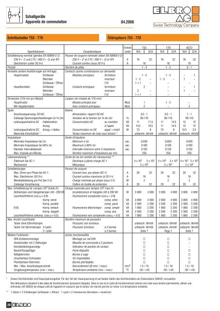
Schaltgeräte<strong>Appareils</strong> <strong>de</strong> <strong>commutation</strong>04.2006Schrittschalter T55 - T70Télérupteurs T55 - T70Einheit T55 T70 ACT2Spezifikationen Caractéristiques Unité 16A 32A 16A 32A 16A 32ASchaltleistung nominal (gemäss EN 60669-2-2) Pouvoir <strong>de</strong> coupure nominale (selon EN 60669-2-2)250 V~ (1 und 2 P) / 400 V~ (3 und 4P) 250 V~ (1 et 2 P) / 400 V~ (3 et 4P) A 16 32 16 32 16 32Gleichstrom (unter 30 V=) Courant continu (sous 30 V=) A 16 16 16Polzahl Nombre <strong>de</strong> pôles 1 - 4 1 - 3 0 - 1Kontakte (an<strong>de</strong>re Ausführungen auf Anfrage) Contacts (autres combinaisons sur <strong>de</strong>man<strong>de</strong>)Hauptmodule Schliesser Modules principaux fermeture 1 - 2 1 - 3 – 1Wechsler inverseur 1 - 2 – 1 - 3 – 1 –Schliesser / Öffner F/O 1 + 1 – – –Hauptkontakte Schliesser Contacts principaux fermeture 2 – – 1Wechsler inverseur 2 – – 1 –Schliesser / Öffner F/O 1 + 1 – – –Dimension (17.6 mm pro Modul)Largeur (en module <strong>de</strong> 17.6 mm)Hauptmodul Module principal seul Mod. 1 1 - 2 –Mit Hauptkontakte Avec contacts principaux Mod. 2 – 2SpuleBobineAnschlussspannung: DC/AC Alimentation: rapport DC/AC 0.5 : 1 0.5 : 1 1 : 1Zulässige Spannungsschwankungen (in % Un) Variation <strong>de</strong> la tension (en % <strong>de</strong> Un) % 90-110 90-110 90-110Leistungsaufnahme AC Haltefunktion Consommation AC au maintien VA 11 11.5 11 14.5 12 12Anzug à l’appel VA 14.5 16.5 11 14.5 12 12Leistungsaufnahme DC Anzug + Halten Consommation en DC appel + maint W 7.5 8 7.5 8 12.5 2.5Maximale Einschaltzeit * Temps maximum <strong>de</strong> mise sous tension * unbeschr. illimité unbeschr. illimité unbeschr. illimitéImpulsdauerDurée d’impulsionMinimale Impulsdauer bei Un Minimum à Un sec. 0.050 0.050 0.050Minimale Impulsdauer bei 90% Un Maximum à 90% Un sec. 0.100 0.100 0.100Kleinster Intervallabstand Intervalle minimum entre 2 impulsions sec. 0.150 0.150 0.150Max. Impulse pro Minute Nombre maximum d’impulsions par min. 250 250 250Lebenserwartung ** Durée <strong>de</strong> vie (en nombre <strong>de</strong> manoeuvres) **Elektrisch bei AC-1 Electrique à pleine charge AC-1 4 x 10 5 3 x 10 5 4 x 10 5 3 x 10 5 4 x 10 5 3 x 10 5Mechanisch Mécanique 2 x 10 6 2 x 10 6 2 x 10 6SchaltleistungenPouvoir <strong>de</strong> coupureMax. Strom pro Phase bei AC-1 Courant max. par phase (AC-1) A 20 32 20 32 20 32Max. Gleichstrom (30 V=) Courant continu maximum (à 30 V=) A 16 16 16Min<strong>de</strong>stbelastung pro Pol (bei 5 V) Charge minimale par phase (sous 5 V) W 2 2 2Zulässige Vorsicherung Calibre du fusible <strong>de</strong> protection A 20 32 20 32 20 32Max. Schaltleistung für Lampen (10 3 Schalt./h) Charge maximale pour lampes (10 3 man./h)Glühlampen und Halogenlampen (40 –200 W) Incan<strong>de</strong>scence et halogène (40 à 200 W) W 3 000 4 000 3 000 4 000 3 000 4 000Leuchtstoffröhren (cos ϕ = 0.9) Fluorescence compensée (cos ϕ = 0.9)Komp. seriel comp. série VA 3 000 4 000 3 000 4 000 3 000 4 000Komp. parallel comp. paral. VA 2 500 3 200 2 500 3 200 2 500 3 200EVG Komp. einfach Fluorescence éléctronique comp. simple VA 1 800 2 200 1 800 2 200 1 800 2 200Komp. doppelt comp. duo VA 2 500 3 200 2 500 3 200 2 500 3 200Leuchtstoffröhren unkomp. (cos ϕ = 0.5) Fluorescence non compensée (cosϕ = 0.5) VA 1 800 2 200 1 800 2 200 1 800 2 200Max. Anzahl LeuchttasterNombre maximum <strong>de</strong> poussoirsTaster ohne Glimmlampen Poussoirs non lumineux unbeschr. illimité unbeschr. illimité unbeschr. illimitéTaster mit Glimmlampen 3-Leiter Poussoirs lumineux à 3 bornes unbeschr. illimité unbeschr. illimité unbeschr. illimité2- Leiter à 2 bornes Seite 7 Page 7 Seite 7Weitere FunktionenAutres fonctionnalitésDIN-Schienenmontage Montage sur rail DIN Handschalter mit 2 Stellungen Manette <strong>de</strong> comman<strong>de</strong> à 2 positions –Kontaktstellungsanzeige Indicateur <strong>de</strong> position <strong>de</strong> contact –Beschriftungsträger Porte-étiquette Käfigklemmen Bornes à cage Unverlierbare Schrauben Vis imperdables Plombierbare Klemmen Bornes plombables Min. / Max. Anschlussquerschnitt Raccor<strong>de</strong>ment (Ø mini. / maxi.) mm 2 1.5 / 10 1.5 / 10 1.5 / 10Umgebungstemperatur (min. / max.) Température ambiante (min. / max.) °C -20 / +45 -20 / +45 -20 / +45* Unsere Schrittschalter sind Dauerspannungsfest. Für <strong>de</strong>n Fall <strong>de</strong>r Dauerspannung ist auf bei<strong>de</strong>n Seiten <strong>de</strong>s Schrittschalters ein Distanzstück (56932) vorzusehen.Nos télérupteurs résistent à <strong>de</strong>s aléas <strong>de</strong> fonctionnement (poussoirs bloqués). Dans le cas où le cycle <strong>de</strong> fonctionnement prévoit une mise sous tension permanente, utiliser uneentretoise (réf 56932) <strong>de</strong> chaque coté <strong>de</strong> l’appareil et s’assurer que le facteur <strong>de</strong> marche permet un retour à la température ambiante.** 1 Zyklus = 2 Schaltungen (schliessen + öffnen) 1 cycle = 2 manoeuvres (fermeture + ouverture)20


