BlackandDecker Meuleuse Petit Diamètre- Kg901 - Type 1 - Instruction Manual (Européen)
BlackandDecker Meuleuse Petit Diamètre- Kg901 - Type 1 - Instruction Manual (Européen)
BlackandDecker Meuleuse Petit Diamètre- Kg901 - Type 1 - Instruction Manual (Européen)
Create successful ePaper yourself
Turn your PDF publications into a flip-book with our unique Google optimized e-Paper software.
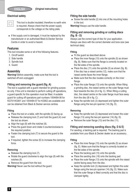
ENGLISH<br />
(Original instructions)<br />
Electrical safety<br />
#<br />
This tool is double insulated; therefore no earth wire<br />
is required. Always check that the power supply<br />
corresponds to the voltage on the rating plate.<br />
u If the supply cord is damaged, it must be replaced by the<br />
manufacturer or an authorised Black & Decker Service<br />
C<strong>en</strong><strong>tre</strong> in order to avoid a hazard.<br />
Features<br />
This tool includes some or all of the following features.<br />
1. On/off switch<br />
2. Side handle<br />
3. Spindle lock<br />
4. Guard<br />
Assembly<br />
Warning! Before assembly, make sure that the tool is<br />
switched off and unplugged.<br />
Fitting and removing the guard (fig. A)<br />
The tool is supplied with a guard int<strong>en</strong>ded for grinding purposes<br />
only. If the unit is int<strong>en</strong>ded to perform cutting off operations,<br />
a guard specific for this operation must be fitted. A suitable<br />
guard for cutting off operations part numbers 1004484-06 for<br />
KG701/KG901 and 1004484-07 for KG902 are available and<br />
can be obtained from Black & Decker service c<strong>en</strong><strong>tre</strong>s.<br />
Fitting<br />
u Place the tool on a table, with the spindle (5) facing up.<br />
u Release the clamping lock (7) and hold the guard (4) over<br />
the tool as shown.<br />
u Align the lugs (8) with the notches (9).<br />
u Press the guard down and rotate it counterclockwise to<br />
the required position.<br />
u Fast<strong>en</strong> the clamping lock (7) to secure the guard to the<br />
tool.<br />
u If required, tight<strong>en</strong> the screw (6) to increase the clamping<br />
force.<br />
Removing<br />
u Release the clamping lock (7).<br />
u Rotate the guard clockwise to align the lugs (8) with the<br />
notches (9).<br />
u Remove the guard from the tool.<br />
Warning! Never use the tool without the guard.<br />
Fitting the side handle<br />
u Screw the side handle (2) into one of the mounting holes<br />
in the tool.<br />
Warning! Always use the side handle.<br />
Fitting and removing grinding or cutting discs<br />
(fig. B - D)<br />
Always use the correct type of disc for your application.<br />
Always use discs with the correct diameter and bore size (see<br />
technical data).<br />
Fitting<br />
u Fit the guard as described above.<br />
u Place the inner flange (10) onto the spindle (5) as shown<br />
(fig. B). Make sure that the flange is correctly located on<br />
the flat sides of the spindle.<br />
u Place the disc (11) onto the spindle (5) as shown (fig. B).<br />
If the disc has a raised c<strong>en</strong><strong>tre</strong> (12), make sure that the<br />
raised c<strong>en</strong><strong>tre</strong> faces the inner flange.<br />
u Make sure that the disc locates correctly on the inner<br />
flange.<br />
u Place the outer flange (13) onto the spindle. Wh<strong>en</strong> fitting<br />
a grinding disc, the raised c<strong>en</strong><strong>tre</strong> on the outer flange must<br />
face towards the disc (A in fig. C). Wh<strong>en</strong> fitting a cutting<br />
disc, the raised c<strong>en</strong><strong>tre</strong> on the outer flange must face away<br />
from the disc (B in fig. C).<br />
u Keep the spindle lock (3) depressed and tight<strong>en</strong> the outer<br />
flange using the two-pin spanner (14) (fig. D).<br />
Removing<br />
u Keep the spindle lock (3) depressed and loos<strong>en</strong> the outer<br />
flange (13) using the two-pin spanner (14) (fig. D).<br />
u Remove the outer flange (13) and the disc (11).<br />
Fitting and removing sanding discs (fig. D & E)<br />
For sanding, a backing pad is required. The backing pad is<br />
available from your Black & Decker dealer as an accessory.<br />
Fitting<br />
u Place the inner flange (10) onto the spindle (5) as shown<br />
(fig. E). Make sure that the flange is correctly located on<br />
the flat sides of the spindle.<br />
u Place the backing pad (15) onto the spindle.<br />
u Place the sanding disc (16) onto the backing pad.<br />
u Place the outer flange (13) onto the spindle with the raised<br />
c<strong>en</strong><strong>tre</strong> facing away from the disc.<br />
u Keep the spindle lock (3) depressed and tight<strong>en</strong> the outer<br />
flange using the two-pin spanner (14) (fig. D). Make sure<br />
that the outer flange is fitted correctly and that the disc is<br />
clamped tightly.<br />
8


