ventilconvettore con inverter fan coil with inverter ventilo-convecteur ...
ventilconvettore con inverter fan coil with inverter ventilo-convecteur ...
ventilconvettore con inverter fan coil with inverter ventilo-convecteur ...

You also want an ePaper? Increase the reach of your titles
YUMPU automatically turns print PDFs into web optimized ePapers that Google loves.
VENTILCONVETTORE CON INVERTER<br />
FAN COIL WITH INVERTER<br />
VENTILO-CONVECTEUR AVEC INVERTER<br />
GEBLÄSEKONVEKTOR MIT INVERTER<br />
FAN COIL CON INVERTER<br />
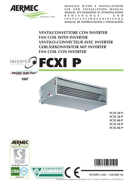
FCXI P<br />
MANUALE D’USO E INSTALLAZIONE<br />
USE AND INSTALLATION MANUAL<br />
MANUEL D’UTILISATION ET D’INSTALLATION<br />
B E D I E N U N G S - U N D<br />
INSTALLATIONSANLEITUNG<br />
MANUAL DE INSTRUCCIONES E INSTALACIÓN<br />
FCXI 20 P<br />
FCXI 30 P<br />
FCXI 40 P<br />
FCXI 50 P<br />
FCXI 80 P<br />
IFCXIPLJ 1203 - 5383900_04<br />
Sostituisce il Replace Remplace le n° Ersetzt Sustituye a: 5383900_03
INDICE INDEX TABLE DES MATIÈRES INHALTSVERZEICHNIS ÍNDICE<br />
DICHIARAZIONE DI CONFORMITÀ<br />
DECLARATION OF CONFORMITY<br />
DÉCLARATION DE CONFORMITÉ 3<br />
KONFORMITÄTSERKLÄRUNG<br />
DECLARACIÓN DE CONFORMIDAD<br />
Trasporto Simboli di sicurezza<br />
Transport Safety symbols<br />
Transport Symboles de sécurité 4<br />
Transport Sicherheitssymbole<br />
Transporte Símbolos de seguridad<br />
Italiano 5<br />
English 13<br />
Français 21<br />
Deutsche 29<br />
Español 37<br />
Dati dimensionali Dimensions Dimensions Abmessungen Dimensiones 45<br />
Schemi elettrici Wiring diagrams Schemas electriques Schaltpläne Esquemas eléctricos 48<br />
SOLUZIONE DEI PROBLEMI<br />
TROUBLE SHOOTING<br />
SOLUTION DES PROBLEMES 53<br />
PROBLEMLÖSUNG<br />
SOLUCIÓN DE PROBLEMAS<br />
Impostazioni di fabbrica della scheda Inverter Inverter card factory settings<br />
Réglages en usine de la platine <strong>inverter</strong> Werkeseinstellungen der Inverterplatine 54<br />
Configuraciones de fábrica de la ficha Inverter
AERMEC S.p.A.<br />
I-37040 Bevilacqua (VR) Italia – Via Roma, 996<br />
Tel. (+39) 0442 633111<br />
Telefax (+39) 0442 93730 – (+39) 0442 93566<br />
www.aermec.com - info@aermec.com<br />
DICHIARAZIONE DI CONFORMITÀ<br />
Noi, fi rmatari della presente, dichiariamo sotto la nostra esclusiva<br />
responsabilità, che il prodotto:<br />
VENTILCONVETTORE<br />
serie FCXI<br />
al quale questa dichiarazione si riferisce è <strong>con</strong>forme alle seguenti norme<br />
armonizzate:<br />
- CEI EN 60335-2-40 - CEI EN 55014-1<br />
- CEI EN 55014-2<br />
- CEI EN 61000-6-1<br />
- CEI EN 61000-6-3<br />
soddis<strong>fan</strong>do così i requisiti essenziali delle seguenti direttive:<br />
- Direttiva Bassa Tensione: LVD 2006/95/CE<br />
- Direttiva Compatibilità Elettromagnetica: EMC 2004/108/CE<br />
- Direttiva Macchine: 2006/42/CE<br />
FCXI CON ACCESSORI<br />
E’ fatto divieto di mettere in servizio il prodotto dotato di accessori<br />
non di fornitura Aermec.<br />
CERTIFICAT DE CONFORMITÉ<br />
Nous soussignés déclarons sous notre exclusive responsabilité que le<br />
produit:<br />
VENTILO-CONVECTEURS<br />
série FCXI<br />
auquel cette déclaration fait référence, est <strong>con</strong>forme aux normes<br />
harmonisées suivantes:<br />
- EN 60335-2-40 - EN 55014-1<br />
- EN 55014-2<br />
- EN 61000-6-1<br />
- EN 61000-6-3<br />
satisfaisant ainsi aux <strong>con</strong>ditions essentielles des directives suivantes:<br />
- Directive Basse Tension: LVD 2006/95/CE<br />
- Directive compatibilité électromagnétique: EMC 2004/108/CE<br />
- Directive Machines: 2006/42/CE<br />
FCXI PLUS ACCESSOIRES<br />
Il est interdit de faire fonctionner l'appareil avec des accessoires qui ne<br />
sont pas fournis de Aermec.<br />
DECLARACIÓN DE CONFORMIDAD<br />
Los que suscriben la presente declaran bajo la propia y exclusiva<br />
responsabilidad que el <strong>con</strong>junto en objeto, defi nido como sigue:<br />
FAN COIL<br />
serie FCXI<br />
al que esta declaración se refi ere, está en <strong>con</strong>formidad a las siguientes<br />
normas armonizadas:<br />
- EN 60335-2-40 - EN 55014-1<br />
- EN 55014-2<br />
- EN 61000-6-1<br />
- EN 61000-6-3<br />
al que esta declaración se refi ere, está en <strong>con</strong>formidad a las siguientes<br />
normas armonizadas:<br />
- Directiva de Baja de Tensión: LVD 2006/95/CE<br />
- Directiva Compatibilidad Clectromagnétic: EMC 2004/108/CE<br />
- Directiva Máquinas: 2006/42/CE<br />
FCXI CON ACCESORIOS<br />
Está prohibido poner en marcha el producto <strong>con</strong> accesorios<br />
no suministrados por Aermec.<br />
FCXI P<br />
CONFORMITY DECLARATION<br />
We the undersigned declare, under our own exclusive responsibility,<br />
that the product:<br />
FAN COIL<br />
FCXI series<br />
to which this declaration refers, complies <strong>with</strong> the following standardised<br />
regulations:<br />
- EN 60335-2-40 - EN 55014-1<br />
- EN 55014-2<br />
- EN 61000-6-1<br />
- EN 61000-6-3<br />
thus meeting the essential requisites of the following directives:<br />
- Low Voltage Directive: LVD 2006/95/EC<br />
- Electromagnetic Compatibility Directive: EMC 2004/108/EC<br />
- Machinery Directive: 2006/42/EC<br />
FCXI WITH ACCESSORIES<br />
It is not allowed to use the unit equipped <strong>with</strong> accessories not supplied<br />
by Aermec.<br />
KONFORMITÄTSERKLÄRUNG<br />
Wir, die hier Unterzeichnenden, erklären auf unsere ausschließlich<br />
Verantwortung, dass das Produkt:<br />
GEBLÄSEKONVEKTOR<br />
der Serie FCXI<br />
auf das sich diese Erklärung bezieht, den folgenden harmonisierten<br />
Normen entspricht:<br />
- EN 60335-2-40 - EN 55014-1<br />
- EN 55014-2<br />
- EN 61000-6-1<br />
- EN 61000-6-3<br />
womit die grundlegenden Anforderungen folgender Richtlinien erfüllt werden:<br />
- Niederspannungsrichtlinie: LVD 2006/95/EG<br />
- Richtlinie zur elektromagnetischen Verträglichkeit: EMC 2004/108/EG<br />
- Maschinenrichtlinie: 2006/42/EG<br />
FCXI + ZUBEHÖR<br />
Falls das Gerät mit Zubehörteilen ausgerüstet wird, die nicht von<br />
Aermec geliefert werden, ist dessen Inbetriebnahme solange untersagt.<br />
La persona autorizzata a costituire il fascicolo tecnico è: / The person authorized to compile the technical file is: / La personne autorisée à <strong>con</strong>stituer<br />
le dossier technique est: / Die Person berechtigt, die technischen Unterlagen zusammenzustellen: Pierpaolo Cavallo<br />
I-37040 Bevilacqua (VR) Italia - Via Roma, 996<br />
Bevilacqua, 01/01/2010 La Direzione Commerciale – Sales and Marketing Director<br />
Luigi Zucchi<br />
IFCXIPLJ 1203 - 5383900_04<br />
3
TRASPORTO CARRIAGE TRANSPORT TRANSPORT TRANSPORTE<br />
SIMBOLI DI SICUREZZA SAFETY SYMBOL SIMBOLES DE SECURITE<br />
SICHERHEITSSYMBOLE SÍMBOLOS DE SEGURIDAD<br />
4<br />
>25Kg<br />
NON bagnare. Tenere al riparo<br />
dalla pioggia<br />
Do NOT wet<br />
CRAINT l’humidité<br />
Vor Nässe schützen<br />
NO mojar<br />
Sovrapponibilità: <strong>con</strong>trollare sull’imballo per <strong>con</strong>oscere il numero di macchine impilabili<br />
Stacking: <strong>con</strong>trol the packing to know the number of machines that can be stacked<br />
Empilement: vérifier sur l’emballage pour <strong>con</strong>naître le nombre d’appareils pouvant être empilés<br />
Stapelung: Die Anzahl der stapelbaren Geräte, wird durch die Symbole auf den Verpackungen ermittelt<br />
Apilamiento: observe en el embalaje para saber cuántos equipos pueden apilarse<br />
Pericolo: Pericolo: Pericolo!!!<br />
Tensione Organi in movimento<br />
Danger: Danger: Danger!!!<br />
Power supply Movings parts<br />
Danger: Danger: Danger!!!<br />
Tension Organes en mouvement<br />
Gefahr ! Gefahr ! Gefahr!!!<br />
Spannung Rotierende Teile<br />
Peligro: Peligro: Peligro!!!<br />
Tensión Elementos en movimiento<br />
IFCXIPLJ 1203 - 5383900_04<br />
NON calpestare<br />
Do NOT step<br />
NE PAS marcher sur cet emballage<br />
Nicht betreten<br />
NO pisar<br />
NON lasciare gli imballi sciolti durante il trasporto - Non rovesciare<br />
Do NOT leave loose packages during transport<br />
ATTACHER les emballages pendant le transport<br />
Die Verpackungen nicht ungesichert transportieren<br />
NO lleve las cajas sueltas durante el transporte<br />
NON trasportare la macchina da soli se il suo peso supera i 25 Kg<br />
DO NOT handle the machine alone if its weight is over 25 Kg<br />
NE PAS transporter tout seul l’appareil si son poids dépasse 25 Kg<br />
Das Gerät NICHT alleine tragen, wenn sein Gewicht 25 Kg überschreitet<br />
NO maneje los equipos en solitario si pesan más de 25 kg<br />
Fragile, maneggiare <strong>con</strong> cura<br />
Fragile, handle <strong>with</strong> care<br />
Fragile, manipuler avec soin<br />
Zerbrechlich, mit Sorgfalt behandeln<br />
Frágil, manejar <strong>con</strong> cuidado<br />
Freccia: alto<br />
Arrow: high<br />
Flèche: haut<br />
Pfeil: hoch<br />
Flecha: alto
Realizzato <strong>con</strong> materiali di qualità superiore, nel rigoroso rispetto delle normative di sicurezza,<br />
FCXI è di facile utilizzo e vi accompagnerà a lungo nell'uso.<br />
Da oggi, grazie alla serie di ventil<strong>con</strong>vettori ad Inverter FCXI di Aermec, la tecnologia brushless<br />
fa il suo ingresso nel campo della climatizzazione ad acqua refrigerata, apportando notevoli<br />
vantaggi di risparmio energetico e di <strong>con</strong>trollo puntuale e preciso della temperatura e<br />
dell'umidità relativa dell'aria degli ambienti climatizzati.<br />
La serie di ventil<strong>con</strong>vettori ad Inverter FCXI è progettata per essere integrata nel sistema VMF.<br />
VMF (Variable Multi Flow) è il sistema in grado di gestire in modo intelligente un impianto<br />
idronico completo, composto quindi da un chiller/pompa di calore, una caldaia, una rete<br />
di ventil<strong>con</strong>vettori (plurivelocità o modulazione <strong>con</strong>tinua della velocità) suddivisi in zone<br />
(fino a 64), le pompe di circolazione (fino a 12) e i recuperatori di calore <strong>con</strong> sonda di<br />
qualità dell’aria (fino a 3), ottimizzando le prestazioni in <strong>con</strong>dizionamento e riscaldamento<br />
garantendo <strong>con</strong>fort e risparmio energetico.<br />
INDICE<br />
Dichiarazione di <strong>con</strong>formità 4<br />
Trasporto Simboli di sicurezza 5<br />
Informazioni importanti Manutenzione Imballo Uso 8<br />
Descrizione Versioni Limiti di funzionamento 9<br />
Componenti principali Descrizione dei componenti 10<br />
Informazioni per l'installazione Allarmi 11<br />
Installazione dell'unità Collegamenti idraulici Collegamenti scarico <strong>con</strong>densa 12<br />
Collegamenti elettrici Impostazione Dip Switch 13<br />
Rotazione della batteria 14<br />
Dimensioni 46<br />
Schemi elettrici 49<br />
SOLUZIONE DEI PROBLEMI 55<br />
OSSERVAZIONI<br />
Conservare i manuali in luogo asciutto, per evitare il deterioramento,<br />
per almeno 10 anni per eventuali riferimenti futuri.<br />
Leggere attentamente e completamente tutte le informazioni<br />
<strong>con</strong>tenute in questo manuale. Prestare particolarmente<br />
attenzione alle norme d’uso accompagnate dalle scritte<br />
“PERICOLO” o “ATTENZIONE” in quanto, se non osservate,<br />
possono causare danno alla macchina e/o a persone e cose.<br />
Per anomalie non <strong>con</strong>template da questo manuale, interpellare<br />
tempestivamente il Servizio Assistenza di zona.<br />
L'apparecchio deve essere installato in maniera tale da rende-<br />
re possibili operazioni di manutenzione e/o riparazione.<br />
La garanzia dell'apparecchio non copre in ogni caso i costi<br />
dovuti ad autoscale, ponteggi o altri sistemi di elevazione che<br />
si rendesero necessari per effettuare gli interventi in garanzia.<br />
AERMEC S.p.A. declina ogni responsabilità per qualsiasi danno<br />
dovuto ad un uso improprio della macchina, ad una lettura<br />
parziale o superficiale delle informazioni <strong>con</strong>tenute in questo<br />
manuale.<br />
Il numero di pagine di questo manuale è: 56.<br />
IFCXIPLJ 1203 - 5383900_04<br />
5<br />
Italiano
Italiano<br />
INFORMAZIONI IMPORTANTI E MANUTENZIONE<br />
ATTENZIONE: il <strong>ventil<strong>con</strong>vettore</strong> è<br />
collegato alla rete elettrica ed al circuito<br />
idraulico, un intervento da parte<br />
di personale non provvisto di specifica<br />
competenza tecnica può causare danni<br />
allo stesso operatore, all’apparecchio ed<br />
all’ambiente circostante.<br />
ALIMENTARE IL VENTILCONVETTO-<br />
RE SOLO CON TENSIONE 230 VOLT<br />
MONOFASE<br />
Utilizzando alimentazioni elettriche<br />
diverse il <strong>ventil<strong>con</strong>vettore</strong> può subire<br />
danni irreparabili.<br />
NON USARE IL VENTILCONVETTORE<br />
IN MODO IMPROPRIO<br />
Il <strong>ventil<strong>con</strong>vettore</strong> non va utilizzato per<br />
allevare, far nascere e crescere animali.<br />
VENTILARE L'AMBIENTE<br />
Si <strong>con</strong>siglia di ventilare periodicamente<br />
l'ambiente ove è installato il <strong>ventil<strong>con</strong>vettore</strong>,<br />
specialmente se nel locale<br />
risiedono parecchie persone o se sono<br />
presenti apparecchiature a gas o sorgenti<br />
di odori.<br />
REGOLARE CORRETTAMENTE LA TEM-<br />
PERATURA<br />
La temperatura ambiente va regolata in<br />
modo da <strong>con</strong>sentire il massimo benessere<br />
alle persone presenti, specialmente se<br />
si tratta di anziani, bambini o ammalati,<br />
evitando sbalzi di temperatura tra interno<br />
ed esterno superiori a 7 °C in estate.<br />
In estate una temperatura troppo bassa<br />
comporta maggiori <strong>con</strong>sumi elettrici.<br />
ORIENTARE CORRETTAMENTE IL<br />
GETTO D'ARIA<br />
L'aria che esce dal <strong>ventil<strong>con</strong>vettore</strong> non<br />
deve investire direttamente le persone;<br />
infatti, anche se a temperatura maggiore<br />
di quella dell'ambiente, può provocare<br />
sensazione di freddo e <strong>con</strong>seguente<br />
disagio.<br />
NON USARE ACQUA TROPPO CALDA<br />
Per pulire il <strong>ventil<strong>con</strong>vettore</strong> usare panni<br />
o spugne morbidi bagnati in acqua al<br />
massimo a 40 °C. Non usare prodotti<br />
chimici o solventi per nessuna parte del<br />
<strong>ventil<strong>con</strong>vettore</strong>. Non spruzzare acqua<br />
sulle superfici esterne o interne del <strong>ventil<strong>con</strong>vettore</strong><br />
(si potrebbero provocare<br />
dei corti circuiti).<br />
PULIRE PERIODICAMENTE IL FILTRO<br />
Una pulizia frequente del filtro garantisce<br />
una maggiore ef fi cienza di funzio-<br />
IMBALLO<br />
I ventil<strong>con</strong>vettori vengono spediti <strong>con</strong> imballo standard costituito da gusci di polistirolo espanso e cartone.<br />
USO<br />
Consultare il manuale del pannello comandi per le modalità d'uso e di installazione.<br />
6<br />
IFCXIPLJ 1203 - 5383900_04<br />
namento.<br />
Controllare se il filtro risulta molto sporco:<br />
nel caso ripetere l’operazione più<br />
spesso.<br />
Pulire frequentemente, togliere la polvere<br />
accumulata <strong>con</strong> un aspiratore.<br />
Quando il filtro è pulito rimontarlo sul<br />
<strong>ventil<strong>con</strong>vettore</strong> procedendo al <strong>con</strong>trario<br />
rispetto allo smontaggio.<br />
PULIZIA STRAORDINARIA<br />
La possibilità di rimuovere le coclee<br />
dei ventilatori ispezionabili (eseguibile<br />
solo da personale provvisto di specifica<br />
competenza tecnica) <strong>con</strong>sente di eseguire<br />
una pulizia accurata anche delle<br />
parti interne, <strong>con</strong>dizione necessaria per<br />
installazioni in luoghi molto affollati o<br />
che richiedono uno standard elevato di<br />
igiene.<br />
DURANTE IL FUNZIONAMENTO<br />
Lasciare sempre il filtro montato sul <strong>ventil<strong>con</strong>vettore</strong><br />
durante il funzionamento,<br />
altrimenti la polvere presente nell'aria<br />
andrà a sporcare le superfici della batteria.<br />
È NORMALE<br />
Nel funzionamento in raffreddamento<br />
può uscire del vapore acqueo dalla mandata<br />
del <strong>ventil<strong>con</strong>vettore</strong>.<br />
Nel funzionamento in riscaldamento un<br />
leggero fruscio d’aria può essere avvertibile<br />
in prossimità del <strong>ventil<strong>con</strong>vettore</strong>.<br />
Talvolta il <strong>ventil<strong>con</strong>vettore</strong> può emettere<br />
odori sgradevoli dovuti all'accumulo di<br />
sostanze presenti nell'aria dell'ambiente<br />
(specialmente se non si provvede a ventilare<br />
periodicamente la stanza, pulire il<br />
filtro più spesso).<br />
Durante il funzionamento si potrebbero<br />
avvertire rumori e scricchiolii interni<br />
all'apparecchio dovuti alle diverse<br />
dilatazioni termiche degli elementi<br />
(plastici e metallici), ciò comunque<br />
non indica un malfunzionamento e non<br />
provoca danni all’unità se non si supera<br />
la massima temperatura dell'acqua di<br />
ingresso.<br />
ATTENZIONE<br />
Si eviti che l'apparecchio sia utilizzato<br />
da bambini o persone inabili senza<br />
opportuna sorveglianza; si ricorda<br />
inoltre che l'apparecchio non deve<br />
essere usato dai bambini come gioco.
DESCRIZIONE DELL’UNITÀ<br />
SCOPO DELLA MACCHINA<br />
Il <strong>ventil<strong>con</strong>vettore</strong> è un terminale per il trattamento dell’aria di un ambiente sia nella stagione invernale sia in quella estiva.<br />
GRANDEZZE DISPONIBILI<br />
I ventil<strong>con</strong>vettori della serie FCXI_P sono disponibili in:<br />
5 grandezze <strong>con</strong> batteria a 3 ranghi<br />
FCXI 20 P<br />
FCXI 30 P<br />
FCXI 40 P<br />
FCXI 50 P<br />
FCXI 80 P<br />
Versione FCXI_P<br />
Ventil<strong>con</strong>vettore Inverter per installazione sia verticale, a parete che orizzontale, in <strong>con</strong>tro soffitto.<br />
Ampia gamma di accessori per raccordare il <strong>ventil<strong>con</strong>vettore</strong> a ogni tipo di canalizzazione dell'aria.<br />
Necessita di pannello comandi esterno (accessorio).<br />
LIMITI DI FUNZIONAMENTO<br />
Temperatura dell’acqua<br />
Al fine di evitare stratificazioni di aria<br />
nell’ambiente, ed avere quindi una<br />
migliore miscelazione, si <strong>con</strong>siglia di non<br />
alimentare il <strong>ventil<strong>con</strong>vettore</strong> <strong>con</strong> acqua<br />
Minima temperatura media dell’acqua<br />
Se il <strong>ventil<strong>con</strong>vettore</strong> funziona in<br />
modo <strong>con</strong>tinuativo in raffreddamento<br />
all’interno di un ambiente <strong>con</strong> elevata<br />
umidità relativa, si potrebbe avere<br />
formazione di <strong>con</strong>densa sulla mandata<br />
dell’aria e all’esterno dell’apparecchio.<br />
Tale <strong>con</strong>densa, potrebbe depositarsi<br />
sul pavimento e sugli eventuali oggetti<br />
sottostanti.<br />
FCXI 20 30 40 50 80<br />
Massima temperatura ingresso acqua °C 80°<br />
Massima temperatura ingresso acqua <strong>con</strong>sigliata °C 65°<br />
Massima pressione d’esercizio bar 8<br />
Minima portata d'acqua l/h 100 100 150 150 300<br />
Massima portata d'acqua l/h 750 750 1100 1150 2200<br />
Limiti di temperatura ambiente (Ta) °C 0° < Ta < 40°<br />
Limiti di umidità relativa nell'ambiente (U.R.) U.R. < 85%<br />
Alimentazione elettrica 230V ( ±10% ) ~ 50Hz<br />
Le prestazioni sono riferite alle seguenti <strong>con</strong>dizioni:<br />
- alla massima velocità motore;<br />
più calda di 65°C.<br />
L’uso di acqua <strong>con</strong> temperature elevate<br />
potrebbe provocare scricchiolii dovuti<br />
alle diverse dilatazioni termiche degli<br />
elementi (plastici e metallici), ciò<br />
Per evitare fenomeni di <strong>con</strong>densazione<br />
sulla struttura esterna dell’apparecchio<br />
<strong>con</strong> ventilatore in funzione, la<br />
temperatura media dell’acqua<br />
non deve essere inferiore ai limiti<br />
riportati nella tabella sottostante, che<br />
dipendono dalle <strong>con</strong>dizioni termoigrometriche<br />
dell’aria ambiente.<br />
I suddetti limiti si riferis<strong>con</strong>o al<br />
funzionamento <strong>con</strong> ventilatore in moto<br />
- la potenza assorbita totale è data dalla somma della potenza<br />
assorbita dall'unità <strong>con</strong> la potenza assorbita dagli accessori<br />
collegati e dichiarata nei relativi manuali.<br />
comunque non provoca danni all’unità<br />
se non si supera la massima temperatura<br />
di esercizio.<br />
alla minima velocità.<br />
In caso di prolungata situazione <strong>con</strong><br />
ventilatore spento e passaggio di<br />
acqua fredda in batteria, è possibile<br />
la formazione di <strong>con</strong>densa all’esterno<br />
dell’apparecchio, pertanto si <strong>con</strong>siglia<br />
l’inserimento dell’accessorio valvola a<br />
tre vie .<br />
MINIMA TEMPERATURA MEDIA ACQUA [°C]<br />
21<br />
Temperatura a bulbo secco dell’aria ambiente<br />
23 25 27 29 31<br />
15 3 3 3 3 3 3<br />
17 3 3 3 3 3 3<br />
Temperatura a bulbo umido<br />
dell’aria ambiente<br />
19 3 3 3 3 3 3<br />
21 6 5 4 3 3 3<br />
23 - 8 7 6 5 5<br />
IFCXIPLJ 1203 - 5383900_04<br />
7<br />
Italiano
Italiano<br />
COMPONENTI PRINCIPALI<br />
1 Mandata dell'aria<br />
2 Batteria di scambio termico<br />
3 Collegamenti idraulici<br />
4 Sfiati d'aria sulla batteria<br />
5 Scarico <strong>con</strong>densa<br />
FCXI 40 P<br />
3 4<br />
Tipologie d’impianto<br />
I ventil<strong>con</strong>vettori sono progettati per<br />
impianti a 2 e 4 tubi, nelle varianti:<br />
- 3R e 4R: senza valvola;<br />
- 3R e 4R: <strong>con</strong> valvola acqua (VCF);<br />
- 3R: <strong>con</strong> batteria ad acqua calda (BV) e<br />
2 valvole (VCF).<br />
Ventilazione<br />
La ventilazione a velocità variabile può<br />
essere comandata sia manualmente che<br />
automaticamente dal pannello comandi.<br />
BATTERIA DI SCAMBIO TERMICO<br />
Batteria <strong>con</strong> tu bo di rame e alettatura in<br />
alluminio bloccata mediante espansione<br />
meccanica dei tubi. I collettori so no<br />
corredati di attacchi femmina e sfiati aria<br />
nella parte alta della batteria.<br />
SEZIONE FILTRANTE<br />
Filtro <strong>con</strong> classe di filtrazione G2, autoestinguenza<br />
B1 (DIN 4102).<br />
Facilmente estraibile e costruito <strong>con</strong><br />
materiali rigenerabili, può essere pulito<br />
mediante lavaggio.<br />
VENTILATORI<br />
È costituito da ventilatori centrifughi a doppia<br />
aspirazione <strong>con</strong> pale sviluppate in lunghezza<br />
per ottenere elevata portata <strong>con</strong> basso<br />
numero di giri. I ventilatori sono direttamente<br />
accoppiati all'albero del motore elettrico<br />
"brushless" ammortizzato <strong>con</strong> supporti elastici.<br />
MOTORE ELETTRICO BRUSHLESS CON<br />
CONTROLLO INVERTER<br />
Il motore elettrico "brushless <strong>con</strong> sonde di<br />
8<br />
3<br />
4<br />
5<br />
DESCRIZIONE<br />
2<br />
IFCXIPLJ 1203 - 5383900_04<br />
6 Bacinella<br />
7 Filtro dell'aria (aspirazione)<br />
8 Ventilatore<br />
9 Motore elettrico <strong>con</strong> dispositivo<br />
Inverter<br />
1<br />
Hall" ed il sistema di <strong>con</strong>trollo utilizzato nei<br />
ventil<strong>con</strong>vettori FCXI di AERMEC nasce dalla<br />
fusione delle più sofisticate tecnologie nel<br />
campo della meccanica e dell'elettronica<br />
sviluppate completamente all'interno del<br />
gruppo industriale. Si tratta di un motore a<br />
magneti permanenti, <strong>con</strong> bassa corrente di<br />
spunto e facilmente regolabile in velocità.<br />
Non risente di disturbi elettromagnetici.<br />
Il fatto che sia senza spazzole permette<br />
minori attriti e una ridotta usura.<br />
Tramite il dispositivo <strong>inverter</strong> dedicato è<br />
possibile <strong>con</strong>trollare la velocità e la coppia<br />
del rotore in modo <strong>con</strong>tinuo, semplicemente<br />
agendo sulle correnti di statore.<br />
Il motore elettrico è ammortizzato <strong>con</strong> supporti<br />
elastici e l'albero in acciaio è montato<br />
su bronzine, la resistenza alla nebbia salina<br />
è testata se<strong>con</strong>do le norme ASTM B117/64.<br />
Il motore elettrico "brushless <strong>con</strong> sonde di<br />
Hall" utilizzato nei ventil<strong>con</strong>vettori modulanti<br />
FCXI di AERMEC presenta enormi vantaggi<br />
rispetto ai tradizionali motori a corrente<br />
alternata ed ai motori ibridi ed <strong>inverter</strong> (senza<br />
sonde di Hall) utilizzati normalmente su altri<br />
ventil<strong>con</strong>vettori modulanti:<br />
- Ridotta usura<br />
- Possibilità di regolare la velocità di rotazione<br />
in modo preciso e <strong>con</strong>tinuo (0-100%)<br />
- Maggiore rendimento energetico<br />
- Maggiore affidabilità e durata<br />
- Basso rumore magnetico<br />
- Controllo <strong>con</strong>tinuo della posizione del rotore<br />
questo implica maggiore efficienza e spunto<br />
garantito e <strong>con</strong>trollato<br />
- Velocità minima garantita 90 rpm (per<br />
ragioni termodinamiche tale limite è stato<br />
10 Pannello di chiusura frontale<br />
11 Ferma filtro<br />
12 Collegamenti elettrici<br />
13 Struttura portante<br />
6 7 8 9 8 10 11 12<br />
portato a 200 rpm).<br />
13<br />
STRUTTURA PORTANTE<br />
È realizzata in lamiera zincata di adeguato<br />
spessore. Nella parte posteriore<br />
ha i fori per il fissaggio a muro dell'apparecchio.<br />
Il gruppo ventilante è chiuso<br />
anteriormente da un pannello metallico.<br />
Ogni apparecchio è corredato di bacinelle<br />
raccolta <strong>con</strong>densa sia per l'installazione<br />
verticale che per l'installazione<br />
orizzontale.<br />
SCARICO CONDENSA<br />
Ogni apparecchio è corredato di bacinelle<br />
raccolta <strong>con</strong>densa <strong>con</strong> collegamento<br />
per la fuori uscita della <strong>con</strong>densa<br />
prodotta dall’unità in raffrescamento.<br />
COLLEGAMENTI IDRAULICI<br />
I collegamenti, posizionati nella fiancata<br />
sinistra, sono ad attacco femmina. È prevista<br />
la possibilità di ruotare la batteria.<br />
Raccordi per mandata ed aspirazione<br />
I ventil<strong>con</strong>vettori FCXI_P sono compatibili<br />
<strong>con</strong> tutti gli accessori già disponibili<br />
per i ventil<strong>con</strong>vettori della serie FCX_P<br />
PANNELLO COMANDI<br />
Utilizzare un pannello comandi <strong>con</strong> termostato<br />
e <strong>con</strong>trollo delle velocità di ventilazione<br />
<strong>con</strong> uscite 0-10V .<br />
Per l'installazione <strong>con</strong>sultare il manuale<br />
dell'accessorio.
INFORMAZIONI PER L'INSTALLAZIONE<br />
ATTENZIONE: prima di effettuare<br />
qualsiasi intervento, assicurarsi che<br />
l’alimentazione elettrica sia disinserita.<br />
ATTENZIONE: prima di effettuare<br />
qualsiasi intervento munirsi di<br />
opportuni dispositivi di protezione<br />
individuale.<br />
ATTENZIONE: L'apparecchio deve<br />
essere installato <strong>con</strong>formemente alle<br />
regole impiantistiche nazionali.<br />
ATTENZIONE: i collegamenti elettrici,<br />
l’installazione dei ventil<strong>con</strong>vettori<br />
e dei loro accessori devono essere<br />
eseguiti solo da soggetti in possesso<br />
dei requisiti tecnico-professionali<br />
di abilitazione all’installazione, alla<br />
trasformazione, all’ampliamento e<br />
alla manutenzione degli impianti ed in<br />
grado di verificare gli stessi ai fini della<br />
sicurezza e della funzionalità.<br />
ATTENZIONE: Installare un dispositivo,<br />
interruttore generale o spina elettrica<br />
che <strong>con</strong>senta di interrompere<br />
completamente l'alimentazione<br />
elettrica dall'apparecchio.<br />
ATTENZIONE: Consultare tutta la<br />
documentazione prima di iniziare<br />
l'installazione.<br />
Vengono qui riportate le indicazioni<br />
essenziali per una corretta installazione<br />
delle apparecchiature.<br />
Si lascia comunque all'esperienza<br />
dell'installatore il perfezionamento<br />
di tutte le operazioni a se<strong>con</strong>da delle<br />
esigenze specifiche.<br />
CODIFICA ALLARMI<br />
Questa sezione è riservata unicamente ai<br />
Centri di Assistenza.<br />
La scheda è posizionata all'interno<br />
dell'unità e ne richiede lo smontaggio.<br />
PERICOLO! Solo il personale<br />
qualificato alla manutenzione può<br />
accedervi.<br />
E’ necessario che le <strong>con</strong>dutture<br />
dell’acqua, dello scarico <strong>con</strong>densa e il<br />
circuito elettrico siano già stati previsti<br />
Il <strong>ventil<strong>con</strong>vettore</strong> deve essere installato<br />
in posizione tale che l’aria possa essere<br />
distribuita in tutta la stanza, che non<br />
vi siano ostacoli (tende o oggetti) al<br />
passaggio dell’aria dalle griglie di<br />
aspirazione.<br />
Il <strong>ventil<strong>con</strong>vettore</strong> deve essere installato<br />
in posizione tale da <strong>con</strong>sentire<br />
facilmente la manutenzione ordinaria<br />
(pulizia del filtro) e straordinaria, oltre<br />
che l’accesso alla valvola di sfiato<br />
dell’aria sulla fiancata del telaio (lato<br />
attacchi).<br />
Non installare l'unità in locali in cui<br />
sono presenti gas infiammabili oppure<br />
sostanze acide od alcaline che possano<br />
danneggiare irrimediabilmente gli<br />
scambiatori di calore in rame-alluminio<br />
o i componenti interni in plastica.<br />
Non installare l'unità in officine o<br />
cucine, dove i vapori d'olio miscelati<br />
all'aria trattata possono depositarsi<br />
sulle batterie di scambio, riducendone<br />
le prestazioni, o sulle parti interne<br />
dell’unità danneggiando i componenti<br />
in plastica.<br />
L’unità FCXI_P è predisposta per i<br />
collegamenti <strong>con</strong> canalizzazioni<br />
per l’aria. Sui ventil<strong>con</strong>vettori della<br />
serie FCXI_P è possibile aumentare<br />
la velocità massima modificando le<br />
impostazioni dei dip switch sul motore.<br />
Nel caso sia installata la valvola a tre<br />
vie, la sonda di minima temperatura<br />
Sulla scheda Inverter sono presenti 2 led<br />
(Alarm / Power) che segnalano lo stato<br />
di funzionamento dell'unità.<br />
La tabella seguente indica come<br />
decodificare i messaggi.<br />
dell’acqua può essere installata in due<br />
posizioni:<br />
- nella sua sede nella batteria,<br />
OBBLIGATORIA se il termostato è<br />
collegato ad un impianto <strong>con</strong> <strong>con</strong>trollo<br />
centralizzato o supervisore (esempio:<br />
VMF-E5);<br />
- al tubo di mandata a monte della<br />
valvola.<br />
Consultare il manuale del termostato<br />
prima di scegliere la posizione<br />
della sonda di minima temperatura<br />
dell’acqua, in funzione della logica<br />
di <strong>con</strong>trollo preferita. Il termostato<br />
potrebbe richiedere di modificare le<br />
impostazioni dei dip-switch interni.<br />
ATTENZIONE: Dopo aver completato<br />
l'installazione verificare il<br />
funzionamento del sistema di scarico<br />
<strong>con</strong>densa, la tenuta dei raccordi<br />
idraulici, l'isolamento dei <strong>con</strong>dotti e<br />
delle tubazioni. Eseguire poi una prova<br />
di funzionamento.<br />
In caso di malfunzionamento <strong>con</strong>sultare<br />
la Tabella di Codifica Allarmi per<br />
interpretare le segnalazioni dei 2 led<br />
(Alarm / Power) che segnalano lo stato<br />
di funzionamento dell'unità.<br />
La scheda Inverter è posizionata<br />
all'interno dell'unità e ne richiede lo<br />
smontaggio.<br />
PERICOLO! Solo il personale<br />
qualificato alla manutenzione può<br />
accedervi.<br />
TIPO ALLARME INDICAZIONI ANOMALIA NOTE<br />
Alta temperatura<br />
Sovratensione<br />
Sottotensione<br />
Sovracorrente<br />
Led ALARM lampeggia<br />
3sec ON 0.5sec OFF<br />
Dopo 1.5min il Led<br />
permanentemente acceso<br />
Motore Spento<br />
IFCXIPLJ 1203 - 5383900_04<br />
Allarme Auto-Restart.<br />
Dopo 1.5min se persistono le<br />
<strong>con</strong>dizioni, l'allarme diventa<br />
permanente, il led Alarm resta<br />
acceso, il sistema si spegne.<br />
Sovracarico<br />
Limitazione della potenza<br />
Led ALARM lampeggia<br />
Riduzione della velocità<br />
0.5sec ON 0.5sec OFF<br />
Controllo di sicurezza Limitazione della temperatura<br />
STOP<br />
Led Alarm permanentemente<br />
acceso<br />
Motore Spento<br />
LEDS<br />
Alarm<br />
Power<br />
Per il reset allarmi:<br />
Set 0V ON INPUT<br />
(togliere tensione e riaccendere)<br />
9<br />
Italiano
Italiano<br />
INSTALLAZIONE<br />
Per installare l’unità procedere come<br />
segue:<br />
- Estrarre il filtro dell’aria.<br />
- Togliere il pannello di chiusura anteriore.<br />
- In caso di installazione a parete mantenere<br />
una distanza minima dal pavimento<br />
di 80 mm.<br />
- In caso di installazione a pavimento<br />
per mezzo degli zoccoli, fare riferimento<br />
alle istruzioni a corredo dell’accessorio.<br />
- Per il fissaggio al muro o al soffitto<br />
usare dei tasselli ad espansione (non<br />
forniti).<br />
Nel caso si utilizzi l’accessorio Supporto<br />
(accessorio AMP), procedere come<br />
COLLEGAMENTI IDRAULICI<br />
- Effettuare i collegamenti idraulici.<br />
- In caso di smontaggio e nuova<br />
installazione, utilizzare guarnizioni<br />
nuove.<br />
La posizione, il tipo e il diametro degli<br />
attacchi idraulici sono riportati nei dati<br />
dimensionali.<br />
Si <strong>con</strong>siglia di isolare adeguatamente le<br />
tubazioni dell’acqua e/o di installare<br />
l’apposita bacinella ausiliaria di<br />
SCARICO CONDENSA<br />
In caso di installazione orizzontale,<br />
montare il raccordo di scarico della<br />
<strong>con</strong>densa fornito a corredo. Si abbia<br />
cura di sigillare <strong>con</strong> sili<strong>con</strong>e la<br />
<strong>con</strong>nessione tra bacinella e raccordo.<br />
La rete di scarico della <strong>con</strong>densa deve<br />
essere opportunamente dimensionata<br />
e le tubazioni posizionate in modo<br />
da mantenere lungo il percorso<br />
un’adeguata pendenza (min.1%). Nel<br />
10<br />
IFCXIPLJ 1203 - 5383900_04<br />
segue:<br />
- montare i 4 supporti ai lati dell’apparecchio<br />
inserendo nell’apposita feritoia<br />
la linguetta superiore e fissando la<br />
parte inferiore al frutto per mezzo delle<br />
viti a corredo.<br />
- Fissare a soffitto le flange mediante<br />
tasselli ad espansione (non forniti); per<br />
le posizioni relative tra flange e frutto<br />
<strong>con</strong>sultare i dati dimensionali.<br />
Eseguire i collegamenti idraulici come<br />
indicato nel capitolo dedicato.<br />
Eseguire il collegamento dello scarico<br />
della <strong>con</strong>densa come indicato nel capitolo<br />
dedicato. I ventil<strong>con</strong>vettori che<br />
raccolta <strong>con</strong>densa, disponibile come<br />
accessorio, per evitare gocciolamenti<br />
durante il funzionamento in<br />
raffreddamento.<br />
Dopo l'installazione verificare la tenuta<br />
dei collegamenti.<br />
caso di scarico nella rete fognaria, si<br />
<strong>con</strong>siglia di realizzare un sifone che<br />
impedisca la risalita di cattivi odori<br />
verso gli ambienti.<br />
Eseguire una prova del funzionamento<br />
e tenuta dell'impianto di scarico<br />
<strong>con</strong>densa versando dell'acqua nella<br />
bacinella.<br />
funzioneranno solamente in riscaldamento<br />
non richiedono lo scarico della<br />
<strong>con</strong>densa.<br />
Eseguire i collegamenti elettrici come<br />
indicato nel capitolo dedicato e quanto<br />
riportato negli schemi elettrici.<br />
Eseguire l'installazione ed i collegamenti<br />
degli eventuali accessori.<br />
Concludere l'installazione rimontando<br />
il pannello anteriore e il filtro dell'aria.<br />
Avviare il <strong>ventil<strong>con</strong>vettore</strong> e verificare<br />
il funzionamento dei componenti e di<br />
tutte le funzioni.<br />
1<br />
B<br />
A<br />
Ø est. 20,5mm<br />
2<br />
B<br />
A<br />
AMP<br />
B<br />
A
COLLEGAMENTI ELETTRICI<br />
L’unità deve essere collegata<br />
direttamente ad un attacco elettrico o<br />
ad un circuito indipendente.<br />
ATTENZIONE: è obbligatorio collegare<br />
i cavi di alimentazione Fase (L) e<br />
Neutro (N) ai rispettivi morsetti, non<br />
invertire i collegamenti, rispettare lo<br />
schema elettrico.<br />
Installare un dispositivo, interruttore<br />
generale o spina elettrica che<br />
<strong>con</strong>senta di interrompere<br />
completamente l'alimentazione<br />
elettrica dall'apparecchio.<br />
Per proteggere l’unità <strong>con</strong>tro i<br />
cortocircuiti, montare sulla linea<br />
di alimentazione un interruttore<br />
onnipolare magnetotermico 2A 250V<br />
(IG) <strong>con</strong> distanza minima di apertura<br />
dei <strong>con</strong>tatti di 3mm .<br />
Si raccomanda l'utilizzo di interruttori<br />
differenziali di tipo B .<br />
Per installazioni <strong>con</strong> fornitura elettrica<br />
trifase si devono <strong>con</strong>siderare i seguenti<br />
Collegamento <strong>con</strong> termostati VMF-E18<br />
Il kit VMF-E18 comprende l’impianto<br />
<strong>con</strong> cavi di collegamento al Modulo<br />
Comando Inverter. I cavi sono<br />
cablati <strong>con</strong> <strong>con</strong>nettori per un rapido<br />
collegamento.<br />
L’installazione del kit VMF-E18<br />
richiede che siano rimosse dal <strong>fan</strong><strong>coil</strong><br />
accorgimenti:<br />
1. In presenza di sezionatori o<br />
magnetotermici 3P + N la corrente<br />
di sgancio deve essere almeno<br />
pari al 170% del valore assorbito<br />
dal complessivo carico dei<br />
ventil<strong>con</strong>vettori per ciascuna fase.<br />
2. La sezione del filo di neutro deve<br />
essere dimensionata <strong>con</strong>siderando<br />
una corrente di esercizio pari al 170%<br />
del valore assorbito dal complessivo<br />
carico dei ventil<strong>con</strong>vettori per<br />
ciascuna fase.<br />
CARATTERISTICHE DEI CAVI DI<br />
COLLEGAMENTO<br />
Usare cavi tipo H05V-K oppure N07V-K<br />
<strong>con</strong> isolamento 300/500 V incassati in<br />
tubo o canalina.<br />
Tutti i cavi devono essere incassati<br />
in tubo o canalina finchè non sono<br />
all’interno del <strong>ventil<strong>con</strong>vettore</strong>.<br />
I cavi all’uscita dal tubo o canalina<br />
devono essere posizionati in modo da<br />
non subire sollecitazioni a trazione o<br />
la morsettiera di serie e i cavi di<br />
collegamento al Modulo Comando<br />
Inverter (Signal e Supply).<br />
Montare la scatola del termostato alla<br />
fiancata del <strong>fan</strong><strong>coil</strong>, sugli attacchi che<br />
erano della morsettiera.<br />
Togliere il coperchio alla scatola del<br />
termostato.<br />
IMPOSTAZIONE DIP SWITCH (solo per le serie P)<br />
Per <strong>con</strong>sentire di adeguare la prevalenza<br />
fornita dal ventilatore alle perdite di<br />
carico del canale, sui ventil<strong>con</strong>vettori<br />
della serie FCXI_P è possibile<br />
aumentare la velocità massima<br />
modificando le impostazioni dei dip<br />
switch sul motore.<br />
DIP SWITCHES<br />
1 - 2 - 3 - 4<br />
FCXI 20 P<br />
FCXI 30 P<br />
FCXI 40 P<br />
FCXI 50 P<br />
FCXI 80 P<br />
torsione e comunque protetti da agenti<br />
esterni.<br />
Cavi a trefolo possono essere usati<br />
solo <strong>con</strong> capicorda. Assicurarsi che i<br />
trefoli dei fili siano ben inseriti.<br />
Gli schemi elettrici sono soggetti ad<br />
un <strong>con</strong>tinuo aggiornamento, è<br />
obbligatorio quindi fare riferimento a<br />
quelli a bordo macchina.<br />
Il pannello comandi non può essere<br />
montato su una parete metallica, salvo<br />
che questa sia collegata alla presa di<br />
terra in modo permanente.<br />
Nell’abbinamento dei pannelli comandi<br />
a distanza deve essere rispettato lo<br />
schema elettrico relativo. Prima<br />
di installare il pannello comandi<br />
leggere attentamente le istruzioni,<br />
se necessario procedere alla<br />
<strong>con</strong>figurazione del pannello.<br />
Collegare la valvola e la sonda alla<br />
morsettiera nelle posizioni indicate<br />
nello schema elettrico.<br />
Collegare il Modulo Comando Inverter<br />
al termostato VMF-E18 utilizzando<br />
l’impianto <strong>con</strong> cavi di collegamento<br />
forniti <strong>con</strong> il kit VMF-E18. Verificare il<br />
collegamento <strong>con</strong> lo schema elettrico.<br />
Completare i collegamenti come<br />
indicato nel manuale del termostato<br />
VMF-E18.<br />
IFCXIPLJ 1203 - 5383900_04<br />
11<br />
Italiano
Italiano<br />
ROTAZIONE DELLA BATTERIA<br />
Se per motivi di allacciamenti idraulici,<br />
si dovesse ruotare la batteria, dopo aver<br />
tolto il pannello di chiusura anteriore,<br />
procedere come segue:<br />
– Togliere la bacinella di raccolta<br />
<strong>con</strong>densa.<br />
– Togliere il coperchio di chiusura della<br />
batteria svitando le viti.<br />
– Togliere le viti che fissano la batteria e<br />
quindi estrarla.<br />
– Rimuovere i semitranciati dalla fiancata<br />
destra.<br />
– Ruotare la batteria e fissarla <strong>con</strong> le viti<br />
precedentemente tolte.<br />
– Rimontare il coperchio di chiusura,<br />
fissandolo <strong>con</strong> le viti.<br />
- Rimontare i tappi in plastica, forniti<br />
a corredo, nei fori lasciati liberi dagli<br />
attacchi idraulici.<br />
- Tutte le bacinelle sono predisposte per<br />
lo scarico della <strong>con</strong>densa su entrambi<br />
i lati. In caso di installazione verticale,<br />
qualora si voglia effettuare lo scarico<br />
della <strong>con</strong>densa sul lato destro, é<br />
necessario spostare a destra il raccordo<br />
di scarico.<br />
– Sfilare i collegamenti elettrici<br />
dalla fiancata destra, rimuovere il<br />
semitranciato e spostare il passacavo<br />
da destra a sinistra.<br />
– Spostare i collegamenti elettrici sul lato<br />
sinistro facendoli passare attraverso il<br />
12<br />
IFCXIPLJ 1203 - 5383900_04<br />
passacavo.<br />
– Spostare la morsettiera, il cavallotto<br />
della messa a terra e gli eventuali<br />
dispositivi elettrici sul lato sinistro sul<br />
lato sinistro.<br />
A<br />
B<br />
180°<br />
A B
Congratulations on your purchase of this Aermec FCXI <strong>fan</strong> <strong>coil</strong>.<br />
Made <strong>with</strong> materials of superior quality in strict compliance <strong>with</strong> safety regulations, "FCXI" is<br />
easy to use and will have a long life.<br />
Thanks to Aermec's FCXI range of <strong>inverter</strong> <strong>fan</strong> <strong>coil</strong>s, brushless technology can now make<br />
inroads in the field of chilled water air <strong>con</strong>ditioning, bringing notable energy savings along<br />
<strong>with</strong> the precise <strong>con</strong>trol of both air temperature and humidity in the air-<strong>con</strong>ditioned rooms.<br />
The range of FCXI <strong>fan</strong> <strong>coil</strong>s are designed for integration in the VMF system.<br />
The VMF (Variable Multi Flow) system is able to intelligently manage a complete hydronic<br />
system, made up of chiller/heat pump, a boiler, a network of <strong>fan</strong> <strong>coil</strong>s (multi-speed or<br />
<strong>con</strong>tinuous modulation of the speed) divided into zones (up to 64), circulation pumps (up<br />
to 12) and heat recovery units <strong>with</strong> air quality sensor (up to 3), optimising <strong>con</strong>ditioning and<br />
heating performance to ensure comfort and energy savings.<br />
TABLE OF CONTENTS<br />
Declaration of <strong>con</strong>formity 4<br />
Carriage Safety symbol 5<br />
Important information and maintenance Operating limits Packaging Use 8<br />
Description Versions Operating limits 9<br />
Main components Description of components 10<br />
Installation information Alarm 11<br />
Unit installation Water <strong>con</strong>nections Condensate discharge <strong>con</strong>nections 12<br />
Electrical <strong>con</strong>nections Dip Switch setting 13<br />
Battery rotation 14<br />
Dimensions 46<br />
Wiring diagram 49<br />
TROUBLE SHOOTING 55<br />
REMARKS<br />
Store the manuals in a dry location to avoid deterioration, as<br />
they must be kept for at least 10 years for any future reference.<br />
All the information in this manual must be carefully read and<br />
understood. Pay particular attention to the operating standards<br />
<strong>with</strong> “DANGER” or “WARNING” signals as failure to<br />
comply <strong>with</strong> them can cause damage to the machine and/or<br />
persons or objects.<br />
If any malfunctions are not included in this manual, <strong>con</strong>tact<br />
the local After-sales Service immediately.<br />
The apparatus must be installed in such a way that maintenan-<br />
ce and/or repair operations are possible.<br />
The apparatus's warranty does not in any case cover costs due<br />
to automatic ladders, scaffolding or other lifting systems necessary<br />
for carrying out repairs under guarantee.<br />
AERMEC S.p.A. declines all responsibility for any damage<br />
whatsoever caused by improper use of the machine, and a partial<br />
or superficial acquaintance <strong>with</strong> the information <strong>con</strong>tained<br />
in this manual.<br />
The number of pages in this manual is : 56.<br />
IFCXIPLJ 1203 - 5383900_04<br />
13<br />
English
English<br />
IMPORTANT INFORMATION AND MAINTENANCE<br />
WARNING: the <strong>fan</strong> <strong>coil</strong> is <strong>con</strong>nected<br />
to the power supply and a water circuit.<br />
Intervention by persons <strong>with</strong>out<br />
the required technical skills can lead<br />
to personal injury to the operator or<br />
damage to the unit and surrounding<br />
objects.<br />
POWER THE FAN COIL ONLY WITH<br />
230V, SINGLE-PHASE VOLTAGE<br />
Any other type of power supply could<br />
permanently damage the <strong>fan</strong> <strong>coil</strong>.<br />
DO NOT USE THE FAN COIL IMPRO-<br />
PERLY<br />
Do not use the <strong>fan</strong> <strong>coil</strong> for animal<br />
husbandry applications (e.g. incubation).<br />
AIR THE ROOM<br />
Periodically air the room in which the<br />
<strong>fan</strong> <strong>coil</strong> has been installed. This is particularly<br />
important if the room is occupied<br />
by many people, or if gas appliances<br />
or sources of odours are present.<br />
ADJUST TEMPERATURE ADEQUATELY<br />
The room temperature should be adjusted<br />
in order to provide maximum<br />
comfort to the people in the room,<br />
especially if they are elderly, children<br />
or sick people; avoid differences over<br />
7°C between the outdoor temperature<br />
and the temperature inside the room in<br />
summer.<br />
In summer, a temperature that is too low<br />
causes higher electrical <strong>con</strong>sumption.<br />
CORRECT AIR JET AIMING<br />
ADJUSTMENT<br />
Air coming out from the <strong>fan</strong> <strong>coil</strong> must<br />
not reach people directly; in fact, even<br />
if the air is warmer than the room temperature,<br />
it could cause a cold sensation<br />
and result in discomfort.<br />
DO NOT USE EXCESSIVELY HOT<br />
WATER<br />
Clean the <strong>fan</strong> <strong>coil</strong> <strong>with</strong> a soft cloth or<br />
sponge soaked in water not over 40°C.<br />
Do not use chemical products or solvents<br />
to clean any part of the <strong>fan</strong> <strong>coil</strong>.<br />
Do not spray water on the outer or<br />
inner surfaces of the <strong>fan</strong> <strong>coil</strong> (it might<br />
cause short circuits).<br />
PACKAGING<br />
The <strong>fan</strong> <strong>coil</strong>s are shipped in standard package which <strong>con</strong>sists of expanded polystyrene foam and cardboard shells.<br />
USE<br />
Consult <strong>con</strong>trol panel manual for installation and use instructions.<br />
14<br />
IFCXIPLJ 1203 - 5383900_04<br />
CLEAN THE FILTER FREQUENTLY<br />
Cleaning the filter frequently guarantees<br />
enhanced operating efficiency.<br />
Check whether the filter is very dirty: if it<br />
is, clean it more often.<br />
Clean frequently; remove the accumulated<br />
dust <strong>with</strong> a vacuum cleaner.<br />
Once the filter is clean, refit it to the <strong>fan</strong><br />
<strong>coil</strong> following the removal instructions<br />
but in reverse order.<br />
SUPPLEMENTARY CLEANING<br />
The fact that the blades of examinable<br />
shrouds can be removed (operation<br />
done only by adequately skilled technicians)<br />
ensures a thorough cleaning<br />
of the internal components, which is<br />
particularly important when installing<br />
the unit in crowded areas or venues<br />
requiring high hygiene standards.<br />
DURING OPERATION<br />
Always leave the filter fitted on the <strong>fan</strong><br />
<strong>coil</strong> during operation (otherwise dust in<br />
the air could soil the <strong>coil</strong> surface area).<br />
WHAT IS NORMAL<br />
In the cooling function, water vapour<br />
may be present in the air delivery of the<br />
<strong>fan</strong> <strong>coil</strong>.<br />
In the heating function, a slight hiss<br />
might be heard close to the <strong>fan</strong> <strong>coil</strong>.<br />
Sometimes the <strong>fan</strong> <strong>coil</strong> might give off<br />
unpleasant smells due to the accumulation<br />
of substances present in the air<br />
of the room (clean the filter more often,<br />
especially if the room is not ventilated<br />
regularly).<br />
While the unit is functioning, there<br />
could be noises and creaks inside<br />
the device due to the various thermal<br />
expansions of the elements (plastic and<br />
metal), but this does not indicate any<br />
malfunction and does not damage the<br />
unit unless the maximum input water<br />
temperature is exceeded.<br />
WARNING<br />
Avoid that the device is used by children<br />
or incompetent persons <strong>with</strong>out<br />
appropriate supervision; also note that<br />
the unit should not be used by children<br />
as a game.
DESCRIPTION OF THE UNIT<br />
MACHINE PURPOSE<br />
The <strong>fan</strong> <strong>coil</strong> is a room air treatment terminal unit for both winter and summer operation.<br />
AVAILABLE SIZES<br />
The FCXI_P <strong>fan</strong> <strong>coil</strong>s are available in:<br />
5 sizes <strong>with</strong> a 3-row <strong>coil</strong><br />
FCXI 20 P<br />
FCXI 30 P<br />
FCXI 40 P<br />
FCXI 50 P<br />
FCXI 80 P<br />
Version FCXI_P<br />
Inverter <strong>fan</strong> <strong>coil</strong> for vertical (wall) or horizontal (suspended ceiling) installation.<br />
TECHNICAL DATA AND OPERATING LIMITS<br />
Water temperature<br />
In order to prevent air stratification in<br />
the room, and therefore to achieve<br />
improved mixing, it is advisable not<br />
to supply the <strong>fan</strong> <strong>coil</strong> <strong>with</strong> water at a<br />
Minimum average water temperature<br />
If the <strong>fan</strong> <strong>coil</strong> is working in <strong>con</strong>tinuous<br />
cooling mode in an environment<br />
where the relative humidity is high,<br />
<strong>con</strong>densate might form on the air<br />
delivery and on the outside of the<br />
device. This <strong>con</strong>densate might be<br />
deposited on any objects underneath<br />
and on the floor.<br />
To avoid <strong>con</strong>densate on the external<br />
FCXI 20 30 40 50 80<br />
Maximum water inlet temperature °C 80°<br />
Maximum recommended water inlet temperature °C 65°<br />
Maximum operating pressure bar 8<br />
Minimum water flow rate l/h 100 100 150 150 300<br />
Maximum water flow rate l/h 750 750 1100 1150 2200<br />
Room temperature limits (Ta) °C 0° < Ta < 40°<br />
Relative humidity limits in the room (R.H.) R.H. < 85%<br />
Power supply 230 V ( ±10% ) ~ 50 Hz<br />
Performance values refer to the following <strong>con</strong>ditions:<br />
- at the maximum motor speed;<br />
temperature over 65°C.<br />
The use of water at high temperatures could<br />
cause squeaking due to the different<br />
thermal expansions of the elements<br />
(plastic and metal), this does not however<br />
structure of the device while the <strong>fan</strong> is<br />
functioning, the average temperature<br />
of the water must not be lower than<br />
the limits shown in the table below,<br />
that depend on the thermo-hygrometric<br />
<strong>con</strong>ditions of the air in the room.<br />
The limits mentioned above refer to<br />
operation while the <strong>fan</strong> is set to its<br />
minimum speed level.<br />
In the event of prolonged <strong>fan</strong> inactivity<br />
- the total input power is determined by adding the input power<br />
for the unit and the input power for the accessories <strong>con</strong>nected<br />
and declared in the corresponding manuals.<br />
cause damage to the unit if the maximum<br />
operating temperature is not exceeded.<br />
and <strong>with</strong> cold water passing through<br />
the <strong>coil</strong>, <strong>con</strong>densate may form on the<br />
external case of the unit. As a result,<br />
we recommend including the 3-way<br />
valve accessory.<br />
MINIMUM AVERAGE WATER TEMPERATURE [°C]<br />
21<br />
Dry bulb ambient air temperature<br />
23 25 27 29 31<br />
15 3 3 3 3 3 3<br />
17 3 3 3 3 3 3<br />
Wet bulb ambient<br />
air temperature<br />
19 3 3 3 3 3 3<br />
21 6 5 4 3 3 3<br />
23 - 8 7 6 5 5<br />
IFCXIPLJ 1203 - 5383900_04<br />
15<br />
English
English<br />
MAIN COMPONENTS<br />
1 Air delivery<br />
2 Heat exchange <strong>coil</strong><br />
3 Water <strong>con</strong>nections<br />
4 Air vents on the <strong>coil</strong><br />
5 Condensate drain<br />
FCXI 40 P<br />
3 4<br />
System types<br />
The <strong>fan</strong> <strong>coil</strong>s are designed for systems<br />
<strong>with</strong> 2 and 4 pipes, in the versions:<br />
- 3R and 4R: <strong>with</strong>out valve;<br />
- 3R and 4R: <strong>with</strong> water valve (VCF);<br />
- 3R: <strong>with</strong> hot water <strong>coil</strong> (BV) and 2 valves<br />
(VCF).<br />
Ventilation<br />
Variable speed ventilation can be commanded<br />
either manually or automatically<br />
from the <strong>con</strong>trol panel.<br />
HEAT EXCHANGE COIL<br />
Coil <strong>with</strong> copper pipe and aluminium<br />
fins blocked by means of the mechanical<br />
expansion of the pipes. The collectors<br />
are fitted <strong>with</strong> female <strong>con</strong>nections and<br />
air vents in the upper part of the <strong>coil</strong>.<br />
FILTERING SECTION<br />
Filter of G2 filtering class.<br />
Easily removable and made from regenerable<br />
materials. May be cleaned by<br />
washing.<br />
FANS<br />
This <strong>con</strong>sists of double suction centrifugal<br />
<strong>fan</strong>s <strong>with</strong> lengthways blades<br />
to obtain a high air flow <strong>with</strong> a low<br />
number of revs. The <strong>fan</strong>s are <strong>con</strong>nected<br />
directly to the "brushless" electric<br />
motor cushioned <strong>with</strong> elastic supports.<br />
BRUSHLESS ELECTRIC MOTOR WITH<br />
INVERTER CONTROL<br />
The "brushless electric motor <strong>with</strong><br />
16<br />
3<br />
4<br />
5<br />
DESCRIPTION<br />
2<br />
IFCXIPLJ 1203 - 5383900_04<br />
6 Tray<br />
7 Air filter (suction)<br />
8 Fan<br />
9 Electric motor <strong>with</strong> Inverter device<br />
10 Front closure panel<br />
1<br />
Hall sensors" and the <strong>con</strong>trol system<br />
used in the AERMEC FCXI <strong>fan</strong> <strong>coil</strong>s<br />
is a combination of sophisticated<br />
technologies in the field of mechanics<br />
and electronics entirely developed<br />
<strong>with</strong>in the industrial group.<br />
This is a permanent magnet motor<br />
<strong>with</strong> low starting current and easy<br />
speed adjustment. Not affected by<br />
electromagnetic interference. The<br />
fact that it is brushless allows lower<br />
friction and less wear. With the<br />
special <strong>inverter</strong> device, it is possible<br />
to <strong>con</strong>trol the speed and torque of the<br />
rotor <strong>con</strong>tinuously, just by means of<br />
the stator currents. The electric motor<br />
is cushioned <strong>with</strong> elastic supports<br />
and the steel shaft is mounted on<br />
bushings and resistance to salt fog<br />
is tested in accordance <strong>with</strong> ASTM<br />
B117/64. The "brushless electric motor<br />
<strong>with</strong> Hall sensors" used in AERMEC<br />
FCXI modulating <strong>fan</strong> <strong>coil</strong>s has huge<br />
advantages over <strong>con</strong>ventional AC<br />
motors and hybrid <strong>inverter</strong> motors<br />
(<strong>with</strong>out Hall sensor) normally used on<br />
other modulating <strong>fan</strong> <strong>coil</strong>s:<br />
- Reduced wear and tear<br />
- The possibility to regulate the rotation<br />
speed in a precise, <strong>con</strong>tinuous manner<br />
(0-100%)<br />
- Higher energy yields<br />
- Longer life and greater reliability<br />
- Low magnetic noise<br />
- Continuous monitoring of the rotor<br />
11 Filter clip<br />
12 Electrical wiring<br />
13 Load-bearing structure<br />
6 7 8 9 8 10 11 12<br />
13<br />
position implies greater efficiency, and<br />
guaranteed and <strong>con</strong>trolled starting<br />
- Guaranteed minimum speed 90 rpm<br />
(for thermodynamic reasons, this limit<br />
was raised to 200 rpm).<br />
LOAD-BEARING STRUCTURE<br />
Made of galvanised sheet iron of a suitable<br />
thickness. There are holes on the<br />
back for fixing the device to the wall.<br />
The <strong>fan</strong> unit is closed at the front <strong>with</strong><br />
a metal panel. Every device is equipped<br />
<strong>with</strong> <strong>con</strong>densate collection trays (for<br />
both vertical and horizontal installation).<br />
CONDENSATE DRAIN<br />
Every device is equipped <strong>with</strong> <strong>con</strong>densate<br />
collection trays, <strong>with</strong> a <strong>con</strong>nection for<br />
draining the <strong>con</strong>densate produced by the<br />
unit in cooling mode.<br />
WATER CONNECTIONS<br />
The <strong>con</strong>nections, located on the left<br />
hand side, are female. The <strong>coil</strong> may also<br />
be rotated.<br />
Delivery and suction couplings<br />
The FCXI_P <strong>fan</strong> <strong>coil</strong>s are compatible<br />
<strong>with</strong> all the accessories already available<br />
for the <strong>fan</strong> <strong>coil</strong>s of the FCX_P range.<br />
CONTROL PANEL<br />
Use a <strong>con</strong>trol panel <strong>with</strong> thermostat and<br />
ventilation speed <strong>con</strong>trol, <strong>with</strong> 0-10V<br />
outputs. Refer to the manual of the<br />
accessory for installation.
INSTALLATION INFORMATION<br />
WARNING: check that the power<br />
supply is dis<strong>con</strong>nected before carrying<br />
out any procedures on the unit.<br />
WARNING:before carrying out any<br />
work, put the proper individual<br />
protection equipment on.<br />
WARNING: the device must be installed<br />
in compliance <strong>with</strong> the national plant<br />
engineering rules.<br />
WARNING: electrical wirings,<br />
installation of the <strong>fan</strong> <strong>coil</strong>s and<br />
relevant accessories should be<br />
performed by a technician who has the<br />
necessary technical and professional<br />
expertise to install, modify, extend and<br />
maintain systems, and who is able to<br />
check the systems for the purposes of<br />
safety and correct operation.<br />
WARNING: install a device, main<br />
switch, or electric plug so you can<br />
fully dis<strong>con</strong>nect the device from the<br />
power supply.<br />
WARNING: Consult all documentation<br />
before starting the installation.<br />
The essential indications to install the<br />
device correctly are given here.<br />
The completion of all the operations<br />
in accordance <strong>with</strong> the specific<br />
requirements is however left to the<br />
experience of the installation engineer.<br />
ALARM CODES<br />
This section is reserved for the After<br />
Sales service only.<br />
The card is located inside the unit and<br />
requires dismantling.<br />
DANGER! Only qualified service<br />
personnel can access it.<br />
The water, <strong>con</strong>densate discharge<br />
and electrical circuit ducts must be<br />
provided for.<br />
The <strong>fan</strong> <strong>coil</strong> must be installed in such a<br />
position that the air can be distributed<br />
throughout the room and so that there<br />
are no obstacles (curtains or objects) to<br />
the passage of the air from the suction<br />
louvers.<br />
The <strong>fan</strong> <strong>coil</strong> should be installed in such<br />
a way as to facilitate routine (filter<br />
cleaning) and special maintenance<br />
operations, as well as access to the<br />
air drain valve on the side of the unit<br />
frame (<strong>con</strong>nections side).<br />
Do not install units in rooms where<br />
there are inflammable gases or acid<br />
or alkaline substances that could<br />
irretrievably damage the aluminiumcopper<br />
heat exchanger or the internal<br />
plastic parts.<br />
Do not install the unit in workshops or<br />
kitchens where the oil vapours mixed<br />
<strong>with</strong> the treated air can be deposited<br />
on the exchange <strong>coil</strong>s, reducing their<br />
performance, or on the parts inside the<br />
unit, damaging the plastic parts.<br />
The FCXI_P unit is prepared for<br />
<strong>con</strong>nection <strong>with</strong> air ducting. The<br />
maximum speed on FCXI_P <strong>fan</strong> <strong>coil</strong>s<br />
can be increased by changing the<br />
settings of the motor dip switches.<br />
There are 2 LEDs on the Inverter card<br />
(Alarm / Power) that indicate the unit's<br />
operating status.<br />
The table below shows how to decode<br />
the messages.<br />
If a three-way valve is installed, the<br />
minimum water temperature sensor<br />
can be installed in two locations:<br />
- in its housing in the <strong>coil</strong>,<br />
MANDATORY if the thermostat is<br />
<strong>con</strong>nected to a system <strong>with</strong> centralised<br />
<strong>con</strong>trol or monitoring device (example:<br />
VMF-E5);<br />
- on the delivery pipe up stream of the<br />
valve.<br />
Check the thermostat manual before<br />
choosing the location of the minimum<br />
water temperature sensor, according<br />
to the preferred <strong>con</strong>trol logic. The<br />
thermostat may need the settings of the<br />
dip-switches changed.<br />
WARNING:After completing the<br />
installation check the operation of the<br />
<strong>con</strong>densate discharge system, the seal<br />
of the hydraulic fittings, insulation<br />
of ducts and pipes. Then perform a<br />
functional test.<br />
In the event of malfunction <strong>con</strong>sult the<br />
Alarm Codes Table to interpret the<br />
alarms indicated by the 2 LEDs (Alarm<br />
/ Power) that indicate the status of the<br />
unit.<br />
The <strong>inverter</strong> card is located inside the<br />
unit and requires dismantling.<br />
DANGER! Only qualified service<br />
personnel can access it.<br />
ALARM TYPE INDICATIONS IRREGULARITY Notes<br />
High temperature<br />
Overvoltage<br />
Undervoltage<br />
Overcurrent<br />
ALARM LED flashes<br />
3sec ON 0.5sec OFF<br />
The LED if permanently ON<br />
after 1.5min<br />
Motor off<br />
IFCXIPLJ 1203 - 5383900_04<br />
Auto-Restart Alarm.<br />
If the <strong>con</strong>ditions persist after<br />
1.5min, the alarm becomes<br />
permanent, the Alarm LED stays<br />
on, the system turns off.<br />
Overload<br />
Power limitation<br />
ALARM LED flashes<br />
Speed reduction<br />
0.5sec ON 0.5sec OFF<br />
Safety <strong>con</strong>trol Temperature limitation<br />
STOP Alarm LED permanently on Motor off<br />
LEDS<br />
Alarm<br />
Power<br />
For alarms reset:<br />
Set 0V ON INPUT<br />
(turn the power off and then on again)<br />
17<br />
English
English<br />
INSTALLING THE UNIT<br />
To install the unit, proceed as follows:<br />
- remove the air filter;<br />
- Remove the front closure panel;<br />
- For wall mounting, maintain a minimum<br />
distance of 80mm from the floor;<br />
- For floor mounting (using feet), refer<br />
to the instructions supplied <strong>with</strong> the<br />
accessory;<br />
- For wall or ceiling mounting, use wall<br />
plugs (not supplied).<br />
When using the Support accessory (AMP<br />
accessory), proceed as follows:<br />
- assemble the 4 supports at the sides of<br />
the device, inserting the hole in the<br />
special slit and fixing the lower part<br />
to the component by means of the<br />
screws supplied;<br />
WATER CONNECTIONS<br />
- Make the water <strong>con</strong>nections.<br />
- In the event of disassembly and<br />
reinstallation, use new gaskets.<br />
Refer to the size data for the position, type<br />
and diameter of the water <strong>con</strong>nections.<br />
You are advised to adequately insulate<br />
water lines and/or fit the auxiliary<br />
<strong>con</strong>densate drain tray (available as an<br />
CONDENSATE DISCHARGE<br />
In the event of horizontal installation,<br />
assemble the <strong>con</strong>densate discharge<br />
<strong>con</strong>nection supplied. Make sure you<br />
seal the <strong>con</strong>nection between the<br />
drip tray and the fitting <strong>with</strong> sili<strong>con</strong>e.<br />
The <strong>con</strong>densate drain network must<br />
be properly scaled and the piping<br />
situated in such a way as to keep an<br />
adequate slope along the route (min.<br />
1%). If <strong>con</strong>densate is discharged into<br />
18<br />
IFCXIPLJ 1203 - 5383900_04<br />
- Fix the flanges to the ceiling, using wall<br />
plugs (not supplied); for the relative<br />
positions between the flanges and the<br />
component, refer to the size data.<br />
Make the water <strong>con</strong>nections as described<br />
in the relative chapter.<br />
Make the <strong>con</strong>densate discharge <strong>con</strong>nection<br />
as described in the relative<br />
chapter. The <strong>fan</strong> <strong>coil</strong>s that work in heat<br />
mode only do not require <strong>con</strong>densate<br />
discharge.<br />
Make the electrical wiring as shown in<br />
the relative chapter and in the wiring<br />
diagrams.<br />
Install and <strong>con</strong>nect any accessories.<br />
accessory), to prevent dripping during<br />
the cooling function.<br />
After installing, check the seal on the<br />
<strong>con</strong>nections.<br />
the sewage system, install a siphon to<br />
prevent the return of unpleasant odours<br />
into the room.<br />
Carry out a functioning and seal test<br />
of the <strong>con</strong>densate drain system by<br />
pouring water into the tray.<br />
Complete the installation by reassembling<br />
the front panel and air filter.<br />
Start up the <strong>fan</strong> <strong>coil</strong> and check all the<br />
components and functions are operating<br />
correctly.<br />
1<br />
B<br />
A<br />
Ø est. 20,5mm<br />
2<br />
B<br />
A<br />
AMP<br />
B<br />
A
ELECTRICAL WIRINGS<br />
The unit must be <strong>con</strong>nected directly<br />
to an electrical outlet or to an<br />
independent circuit.<br />
WARNING: it is compulsory to <strong>con</strong>nect<br />
the power cables Phase (L) and Neutral<br />
(N) to the respective terminals, do not<br />
to reverse the <strong>con</strong>nections, and observe<br />
the wiring diagram.<br />
install a device, main switch, or electric<br />
plug so you can fully dis<strong>con</strong>nect the<br />
device from the power supply.<br />
To protect the unit against short<br />
circuits, fit an omnipolar thermalmagnetic<br />
trip 2A 250V (IG) to the<br />
power line <strong>with</strong> a minimum <strong>con</strong>tact<br />
opening distance of 3mm.<br />
The use of B-type circuit breakers is<br />
recommended.<br />
For installations <strong>with</strong> three-phase power<br />
supply, the following precautions<br />
Connection <strong>with</strong> VMF-E18 thermostats<br />
The VMF-E18 Kit includes the system<br />
<strong>with</strong> <strong>con</strong>nection cables to the Inverter<br />
Control Module. The cables are wired<br />
<strong>with</strong> <strong>con</strong>nectors for quick <strong>con</strong>nection.<br />
The installation of the VMF-E18 kit<br />
requires that standard <strong>con</strong>trol board and<br />
<strong>con</strong>nection cables to the Inverter Control<br />
DIP SWITCH SETTING (for the P series only)<br />
To help adapt the head provided by<br />
the <strong>fan</strong> to the pressure drops of the<br />
duct, the maximum speed of the<br />
FCXI_P series <strong>fan</strong> <strong>coil</strong> can be increased<br />
by changing the settings of the dip<br />
switches on the motor.<br />
DIP SWITCHES<br />
1 - 2 - 3 - 4<br />
should be <strong>con</strong>sidered:<br />
1. In the presence of breakers or<br />
thermomagnetic switches 3P + N,<br />
the triggering current must be at least<br />
170% of the total load absorbed by<br />
the <strong>fan</strong> <strong>coil</strong>s for each phase.<br />
2. The section of the neutral wire must be<br />
of a dimension taking into <strong>con</strong>sideration<br />
the operating current equal to 170% of<br />
the total load absorbed by the <strong>fan</strong> <strong>coil</strong>s<br />
for each phase.<br />
CHARACTERISTICS OF THE<br />
CONNECTION CABLES<br />
Use H05V-K or N07V-K type cables<br />
<strong>with</strong> 300/500V <strong>with</strong> insulation, piped<br />
or ducted.<br />
All the cables must be piped or ducted<br />
until they are inside the <strong>fan</strong> <strong>coil</strong>.<br />
The cables leaving the pipe or raceway<br />
must be so positioned that they are<br />
not pulled or twisted and are anyway<br />
Module (Signal and Supply) are removed<br />
from the <strong>fan</strong> <strong>coil</strong>.<br />
Mount the thermostat housing to the side<br />
of the <strong>fan</strong> <strong>coil</strong> units, on the <strong>con</strong>nections<br />
that were of the <strong>con</strong>trol board.<br />
Remove the cover of the thermostat<br />
housing.<br />
Connect the <strong>inverter</strong> <strong>con</strong>trol module<br />
FCXI 20 P<br />
FCXI 30 P<br />
FCXI 40 P<br />
FCXI 50 P<br />
FCXI 80 P<br />
protected from outside agents.<br />
Stranded cables can only be used <strong>with</strong><br />
crimping terminals. Check the wire<br />
strands are well inserted.<br />
The wiring diagrams are subject to<br />
<strong>con</strong>tinuous updates, so it is essential<br />
to use those on the machine as your<br />
reference.<br />
The <strong>con</strong>trol panel may not be fitted on<br />
a metal wall unless this is permanently<br />
<strong>con</strong>nected to an earthed outlet.<br />
When using remote <strong>con</strong>trol panels,<br />
the relative wiring diagram must be<br />
respected. Before installing the <strong>con</strong>trol<br />
panel, read the instructions carefully<br />
and <strong>con</strong>figure the panel if necessary.<br />
Connect the valve and sensor to the<br />
<strong>con</strong>trol board, in the positions<br />
indicated in the wiring diagram.<br />
VMF-E18 to the thermostat using the<br />
system <strong>with</strong> <strong>con</strong>nection cables supplied<br />
<strong>with</strong> the VMF-E18 kit. Check the<br />
<strong>con</strong>nection <strong>with</strong> the wiring diagram.<br />
Complete the <strong>con</strong>nections as indicated<br />
in the VMF-E18 thermostat manual.<br />
IFCXIPLJ 1203 - 5383900_04<br />
19<br />
English
English<br />
ROTATING THE COIL<br />
If the hydraulic <strong>con</strong>nections require the<br />
rotation of the <strong>coil</strong>, remove the front<br />
closure panel and proceed as follows:<br />
- Remove the <strong>con</strong>densate drip tray;<br />
- Undo the screws and remove the <strong>coil</strong><br />
cover;<br />
- Remove the screws securing the <strong>coil</strong>,<br />
then remove the <strong>coil</strong>;<br />
- Remove the push-outs on the righthand<br />
side;<br />
- Rotate the <strong>coil</strong> and secure it <strong>with</strong> the<br />
previously removed screws;<br />
- Reassemble the cover and fix it <strong>with</strong><br />
the screws;<br />
- Reassemble the plastic plugs (supplied)<br />
in the holes left free by the water<br />
<strong>con</strong>nections;<br />
- All the trays can be used to collect<br />
<strong>con</strong>densate on both sides. In case of<br />
vertical installation, to discharge<br />
<strong>con</strong>densate on the right side, position<br />
the drain <strong>con</strong>nection to the right;<br />
- Slide out the electrical wirings from the<br />
right-hand side, remove the push-out<br />
and move the cable grommet from the<br />
right to the left side;<br />
- Transfer the electrical wirings to the left<br />
side through the cable grommet;<br />
- Move the <strong>con</strong>trol board, the earthing<br />
u-bolt and any electric devices to the<br />
left-hand side.<br />
20<br />
IFCXIPLJ 1203 - 5383900_04<br />
A<br />
B<br />
180°<br />
A B
Nous désirons vous féliciter pour avoir acheté le <strong>ventilo</strong>-<strong>con</strong>vecteur FCXI Aermec.<br />
Réalisé avec des matériaux de qualité supérieure, dans le plus grand respect des règles de<br />
sécurité, le modèle FCXI est facile à utiliser et a été <strong>con</strong>çu pour durer longtemps.<br />
Grâce à la série de <strong>ventilo</strong>-<strong>con</strong>vecteurs à <strong>inverter</strong> FCXI d'Aermec, la technologie brushless fait<br />
désormais son entrée dans le domaine de la climatisation à eau refroidie, tout en apportant<br />
d'avantages <strong>con</strong>sidérables en termes d'é<strong>con</strong>omie d'énergie et de commande exacte et précise<br />
de la température et de l'humidité relative de l'air des locaux climatisés.<br />
La série de <strong>ventilo</strong>-<strong>con</strong>vecteurs à FCXI est <strong>con</strong>çue pour être intégrée dans le système VMF.<br />
VMF (Variable Multi Flow) est le système en mesure de gérer de manière intelligente une<br />
installation hydronique complète, il est donc composé d'un chiller/pompe à chaleur, d'une<br />
chaudière, d'un réseau de <strong>ventilo</strong>-<strong>con</strong>vecteurs (à plusieurs vitesses ou à modulation <strong>con</strong>tinue de<br />
la vitesse) divisés en zones (jusqu'à 64), de pompes de circulation (jusqu'à 12) et de récupérateurs<br />
de chaleur avec sonde de qualité de l'air (jusqu'à 3), en vue d'optimiser les performances de<br />
climatisation de l'air et du chauffage tout en assurant le <strong>con</strong>fort et l'é<strong>con</strong>omie d'énergie.<br />
TABLE DES MATIÈRES<br />
Certificat de <strong>con</strong>formité 4<br />
Transport Symboles de securité 5<br />
Informations importantes et entretien Emballage Utilisation 24<br />
Description Versions Limites de fonctionnement 25<br />
Composants principaux Description des composants 26<br />
Informations pour l'installation Alarmes 27<br />
Installation de l'unité Raccords hydrauliques Raccords d'évacuation des <strong>con</strong>densats 28<br />
Branchements électriques Réglage des commuteteurs Dip 29<br />
Rotation batterie 30<br />
Dimensions 46<br />
Schemas electriques 49<br />
SOLUTION DES PROBLEMES 55<br />
REMARQUES<br />
Conserver les manuels dans un endroit sec, afin d’éviter leur<br />
détérioration, pendant au moins 10 ans, pour toutes éventuelles<br />
<strong>con</strong>sultations futures.<br />
Lire attentivement et entièrement toutes les informations <strong>con</strong>tenues<br />
dans ce manuel. Prêter une attention particulière aux<br />
normes d’utilisation signalées par les inscriptions “DANGER”<br />
ou “ATTENTION”, car leur non observance pourrait causer un<br />
dommage à l’appareil et/ou aux personnes et objets.<br />
Pour toute anomalie non mentionnée dans ce manuel, <strong>con</strong>tacter<br />
aussitôt le service après-vente de votre secteur.<br />
Lors de l'installation de l'appareil, il faut prévoir l'espace<br />
nécessaire pour les opérations d'entretien et/ou de réparation.<br />
La garantie de l'appareil ne couvre pas les coûts dérivant de<br />
l'utilisation de voitures avec échelle mécanique, d'échafaudages<br />
ou d'autres systèmes de levée employés pour effectuer des<br />
interventions en garantie.<br />
AERMEC S.p.A. décline toute responsabilité pour tout dommage<br />
dû à une utilisation impropre de l’appareil et à une lecture<br />
partielle ou superficielle des informations <strong>con</strong>tenues dans ce<br />
manuel.<br />
Ce manuel se compose de pages: 56<br />
IFCXIPLJ 1203 - 5383900_04<br />
21<br />
Français
Français<br />
INFORMATIONS IMPORTANTES ET ENTRETIEN<br />
ATTENTION : le <strong>ventilo</strong>-<strong>con</strong>vecteur est<br />
branché au réseau électrique et au<br />
circuit hydraulique : l’intervention de<br />
personnel sans la compétence technique<br />
spécifique peut entraîner des blessures<br />
pour l’opérateur ou endommager<br />
l’appareil ou le milieu environnant.<br />
ALIMENTER LE VENTILO-CONVEC-<br />
TEUR EXCLUSIVEMENT AVEC UNE<br />
TENSION DE 230 V, MONOPHASÉE<br />
L'utilisation d'alimentations électriques<br />
différentes peut endommager le <strong>ventilo</strong>-<strong>con</strong>vecteur<br />
irrémédiablement.<br />
NE PAS UTILISER LE VENTILO-<br />
CONVECTEUR DE MANIÈRE IMPRO-<br />
PRE<br />
Le <strong>ventilo</strong>-<strong>con</strong>vecteur ne doit pas être<br />
utilisé pour l’élevage, la naissance ou<br />
la croissance d’animaux.<br />
VENTILER LA PIÈCE<br />
Il est <strong>con</strong>seillé de ventiler périodiquement<br />
la pièce où le <strong>ventilo</strong>-<strong>con</strong>vecteur<br />
est installé, plus spécialement si plusieurs<br />
personnes l'utilisent ou si des<br />
appareils à gaz ou des sources d’odeurs<br />
s'y trouvent.<br />
PROGRAMMER CORRECTEMENT LA<br />
TEMPÉRATURE<br />
La température ambiante doit être réglée<br />
de manière à garantir un maximum<br />
de bien-être aux personnes présentes,<br />
surtout s'il s'agit de personnes âgées,<br />
d'en<strong>fan</strong>ts ou de malades, en évitant des<br />
sauts de température entre l'intérieur et<br />
l'extérieur de plus de 7 °C en été.<br />
En été, une température trop basse comporte<br />
une augmentation de la <strong>con</strong>sommation<br />
d'électricité.<br />
ORIENTER CORRECTEMENT LE JET<br />
D'AIR<br />
L'air qui sort du <strong>ventilo</strong>-<strong>con</strong>vecteur ne<br />
doit pas souffler directement sur les<br />
personnes ; car même s'il est à une<br />
température supérieure à celle de la<br />
pièce, il peut provoquer une sensation<br />
de froid et être gênant.<br />
NE PAS UTILISER DE L'EAU TROP<br />
CHAUDE<br />
Pour nettoyer le <strong>ventilo</strong>-<strong>con</strong>vecteur, utiliser<br />
des chiffons ou des éponges souples<br />
et mouillés avec de l’eau dont la<br />
température maximale ne dépasse pas<br />
40 °C. N’utiliser aucun produit chimique<br />
ou solvant pour nettoyer une partie<br />
quel<strong>con</strong>que du <strong>ventilo</strong>-<strong>con</strong>vecteur. Ne<br />
EMBALLAGE<br />
Les <strong>ventilo</strong>-<strong>con</strong>vecteurs sont envoyés dans un emballage standard <strong>con</strong>stitué de coques en polystyrène expansé et en carton.<br />
EMPLOI<br />
Consulter le manuel du panneau de commande pour le mode d'emploi et l'installation.<br />
22<br />
IFCXIPLJ 1203 - 5383900_04<br />
pas vaporiser de l'eau sur les surfaces<br />
externes ou internes du <strong>ventilo</strong>-<strong>con</strong>vecteur<br />
(on risque des courts-circuits).<br />
NETTOYER LE FILTRE PÉRIODIQUE-<br />
MENT<br />
Un nettoyage fréquent du filtre garantit<br />
une plus grande efficacité de fonctionnement.<br />
Contrôler si le filtre est particulièrement<br />
sale : dans ce cas, répéter l'opération<br />
plus fréquemment.<br />
Nettoyer fréquemment et enlever la<br />
poussière accumulée avec un aspirateur.<br />
Lorsque le filtre est propre, le remonter<br />
sur le <strong>ventilo</strong>-<strong>con</strong>vecteur en effectuant<br />
les opérations en sens inverse au<br />
démontage.<br />
NETTOYAGE EXTRAORDINAIRE<br />
La possibilité d'enlever les vis sans fin<br />
des ventilateurs (à effectuer seulement<br />
par du personnel possédant les compétences<br />
spécifiques), permet de réaliser<br />
un nettoyage soigné de l'intérieur,<br />
<strong>con</strong>dition nécessaire pour l'installation<br />
dans des lieux bondés qui demandent<br />
un niveau d'hygiène très élevé.<br />
PENDANT LE FONCTIONNEMENT<br />
Pendant la marche, laisser le filtre toujours<br />
monté sur le <strong>ventilo</strong>-<strong>con</strong>vecteur<br />
car autrement la poussière qui se trouve<br />
dans l'air peut salir la surface de la<br />
batterie.<br />
IL EST NORMAL<br />
Durant le fonctionnement en mode<br />
refroidissement, de la vapeur d’eau<br />
peut sortir du refoulement du <strong>ventilo</strong><strong>con</strong>vecteur.<br />
Pendant le fonctionnement en mode<br />
chauffage, on peut entendre un léger<br />
bruissement d'air près du <strong>ventilo</strong>-<strong>con</strong>vecteur.<br />
Parfois le <strong>ventilo</strong>-<strong>con</strong>vecteur<br />
peut émettre des odeurs désagréables<br />
dues à l'accumulation de substances<br />
présentes dans l'air ambiant (notamment,<br />
si la pièce n'est pas aérée périodiquement,<br />
nettoyer le filtre plus fréquemment).<br />
Pendant le fonctionnement, on peut<br />
entendre des bruits et des craquements<br />
internes de l'appareil dus aux<br />
différentes dilatations thermiques<br />
de ses éléments (en plastique ou en<br />
métal) ; cela n'est pas signe de mauvais<br />
fonctionnement ni ne provoque aucun<br />
dommage à l'unité si l'on ne dépasse<br />
pas la température maximale de l'eau<br />
en entrée.<br />
ATTENTION<br />
Éviter que des en<strong>fan</strong>ts ou des personnes<br />
incapables utilisent l'appareil sans une<br />
surveillance opportune ; en outre, il est<br />
rappelé que les en<strong>fan</strong>ts ne doivent pas<br />
utiliser l'appareil comme un jouet.
DESCRIPTION DE L'UNITÉ<br />
FINALITÉ DE L'APPAREIL<br />
Le <strong>ventilo</strong>-<strong>con</strong>vecteur est un terminal pour le traitement de l’air d’un milieu, tant en hiver qu’en été.<br />
GRANDEURS DISPONIBLES<br />
Les <strong>ventilo</strong>-<strong>con</strong>vecteurs de la série FCXI_P sont disponibles en :<br />
5 grandeurs avec batterie à 3 rangs<br />
FCXI 20 P<br />
FCXI 30 P<br />
FCXI 40 P<br />
FCXI 50 P<br />
FCXI 80 P<br />
Version FCXI_P<br />
Ventilo-<strong>con</strong>vecteur <strong>inverter</strong> pour installation verticale, murale, ou horizontale, en faux plafond.<br />
DONNÉES TECHNIQUES ET LIMITES DE FONCTIONNEMENT<br />
Température de l'eau<br />
Pour éviter des stratifications de l'air<br />
ambiant et avoir un meilleur mélange, il<br />
est <strong>con</strong>seillé de ne pas alimenter le <strong>ventilo</strong>-<strong>con</strong>vecteur<br />
avec de l'eau ayant une<br />
Température moyenne minimale de l'eau<br />
Si le <strong>ventilo</strong>-<strong>con</strong>vecteur fonctionne de<br />
façon <strong>con</strong>tinue en mode refroidissement<br />
dans un milieu où l'humidité<br />
relative est élevée, il pourrait se former<br />
de la <strong>con</strong>densation sur le refoulement de<br />
l'air et à l'extérieur de l'appareil. Cette<br />
<strong>con</strong>densation pourrait se déposer au sol<br />
et sur les objets éventuellement situés<br />
au-dessous.<br />
FCXI 20 30 40 50 80<br />
Température maximale de l'eau en entrée °C 80°<br />
Température maximale <strong>con</strong>seillée de l'eau en entrée °C 65°<br />
Pression de service maximale bar 8<br />
Débit minimal d'eau l/h 100 100 150 150 300<br />
Débit maximal d'eau l/h 750 750 1100 1150 2200<br />
Limites de température ambiante (Ta) °C 0° < Ta < 40°<br />
Limites d'humidité relative ambiante (H.R.) H.R. < 85 %<br />
Alimentation électrique 230 V ( ±10 % ) ~ 50 Hz<br />
Performances mesurées selon les <strong>con</strong>ditions suivantes :<br />
- au régime moteur maximum ;<br />
TEMPÉRATURE MOYENNE DE L'EAU [°C]<br />
Température à bulbe humide<br />
de l’air ambiant<br />
température supérieure à 65 °C.<br />
L’utilisation d'eau à des températures<br />
élevées pourrait provoquer des craquèlements<br />
dus aux différentes dilatations<br />
thermiques des éléments (plastiques et<br />
Pour éviter des phénomènes de <strong>con</strong>densation<br />
sur la structure extérieure de l'appareil<br />
lorsque le ventilateur est en marche,<br />
la température moyenne de l'eau ne doit<br />
pas être inférieure aux limites indiquées<br />
dans le tableau ci-dessous ; ces limites<br />
dépendent des <strong>con</strong>ditions thermohygrométriques<br />
de l'air ambiant.<br />
Ces limites se rapportent au fonctionnement<br />
du ventilateur à la vitesse minimale.<br />
- la puissance absorbée totale est donnée par la somme de la puissance<br />
absorbée par l'unité avec la puissance absorbée par les<br />
accessoires reliés et déclarée dans les manuels correspondants.<br />
métalliques), ce qui toutefois ne provoquera<br />
pas de dégâts à l'unité si la température<br />
maximale de fonctionnement<br />
n'est pas dépassée.<br />
Si le ventilateur doit rester éteint pendant<br />
longtemps et que de l'eau froide passe<br />
dans la batterie, il se peut que des<br />
<strong>con</strong>densats se forment à l'extérieur de<br />
l'appareil. Il est donc <strong>con</strong>seillé d'installer<br />
la vanne à trois voies (accessoire).<br />
Température à bulbe sec de l'air ambiant<br />
21 23 25 27 29 31<br />
15 3 3 3 3 3 3<br />
17 3 3 3 3 3 3<br />
19 3 3 3 3 3 3<br />
21 6 5 4 3 3 3<br />
23 - 8 7 6 5 5<br />
IFCXIPLJ 1203 - 5383900_04<br />
23<br />
Français
Français<br />
COMPOSANTS PRINCIPAUX<br />
1 Refoulement de l'air<br />
2 Batterie d'échange thermique<br />
3 Raccords hydrauliques<br />
4 Purges d'air sur la batterie<br />
5 Évacuation des <strong>con</strong>densats<br />
FCXI 40 P<br />
3 4<br />
DESCRIPTION<br />
Types de systèmes<br />
Les <strong>ventilo</strong>-<strong>con</strong>vecteurs sont <strong>con</strong>çus<br />
pour des systèmes à 2 et à 4 tubes,<br />
dans les variantes suivantes :<br />
- 3R et 4R : sans vanne ;<br />
- 3R et 4R : avec vanne d'eau (VCF) ;<br />
- 3R : avec batterie d'eau chaude (BV) et<br />
2 vannes (VCF).<br />
Ventilation<br />
La ventilation à vitesse variable peut être<br />
commandée depuis le panneau de commande,<br />
en mode manuel ou automatique.<br />
BATTERIE D'ÉCHANGE THERMIQUE<br />
Batterie avec tuyau en cuivre et ailettes en<br />
aluminium, bloquée par l'expansion mécanique<br />
des tuyaux. Les collecteurs sont livrés<br />
avec raccords femelles et purges d'air dans<br />
la partie haute de la batterie.<br />
SECTION FILTRANTE<br />
Filtre de classe G2. Facilement démontable,<br />
fabriqué en matériaux recyclables,<br />
nettoyable par lavage.<br />
VENTILATEURS<br />
Il se compose de ventilateurs centrifuges<br />
à double aspiration avec des pales très<br />
longues dans le but d'obtenir une débit<br />
élevé avec un faible nombre de tours. Les<br />
ventilateurs sont directement accouplés<br />
à l'arbre du moteur électrique sans balai<br />
amorti à l'aide de supports élastiques.<br />
MOTEUR ÉLECTRIQUE SANS BALAI<br />
AVEC COMMANDE INVERTER<br />
Le moteur électrique sans balai avec des<br />
sondes de Hall et le système de commande<br />
utilisé dans le <strong>ventilo</strong>-<strong>con</strong>vecteurs<br />
FCXI d'AERMEC naît de la fusion des<br />
technologies les plus sophistiquées dans<br />
24<br />
3<br />
4<br />
5<br />
2<br />
IFCXIPLJ 1203 - 5383900_04<br />
6 Bac<br />
7 Filtre d'air (reprise)<br />
8 Ventilateur<br />
9 Moteur électrique avec dispositif <strong>inverter</strong><br />
10 Panneau de fermeture avant<br />
1<br />
le domaine de la mécanique et de l'électroniques<br />
développées complètement à<br />
l'intérieur du groupe industriel. Il s'agit<br />
d'un moteur à aimants permanents, avec<br />
basse intensité de démarrage et dont la<br />
vitesse est facilement réglable. Il n'est<br />
pas affecté par des perturbations électromagnétiques.<br />
Étant donné qu'il est<br />
sans balai, il y a peu de frottements et<br />
l'usure est réduite. Un dispositif <strong>inverter</strong><br />
spécifique permet de <strong>con</strong>trôler la<br />
vitesse et le couple du rotor de manière<br />
<strong>con</strong>tinue, tout simplement en agissant<br />
sur les courants du stator. Le moteur<br />
électrique est amorti avec des supports<br />
élastiques et l'arbre en acier est monté<br />
sur des roulements, sa résistance au<br />
brouillard salin est essayé selon les<br />
normes ASTM B117/64. Le moteur électrique<br />
sans balai avec sondes de Hall<br />
utilisé dans les <strong>ventilo</strong>-<strong>con</strong>vecteurs<br />
modulants FCXI d'AERMEC présente<br />
de grandes avantages par rapport aux<br />
moteurs traditionnels à courant alternatif<br />
et aux moteurs hybrides et <strong>inverter</strong> (sans<br />
sondes de Hall) utilisés normalement sur<br />
d'autres <strong>ventilo</strong>-<strong>con</strong>vecteurs modulants :<br />
- Usure réduite ;<br />
- Possibilité de régler la vitesse de rotation<br />
de manière précise et <strong>con</strong>tinue<br />
(0-100 %) ;<br />
- Rendement énergétique supérieur ;<br />
- Fiabilité et durée de vie supérieures ;<br />
- Bas bruit magnétique ;<br />
- Commande <strong>con</strong>tinue de la position du rotor<br />
ce qui implique une plus grande efficacité<br />
et un démarrage garanti et commandé ;<br />
11 Collier de serrage du filtre<br />
12 Branchements électriques<br />
13 Structure porteuse<br />
6 7 8 9 8 10 11 12<br />
13<br />
- Vitesse minimale garantie de 90 tr/min<br />
(pour des raisons thermodynamiques<br />
cette limite a été portée à 200 tr/min).<br />
STRUCTURE PORTEUSE<br />
Elle est <strong>con</strong>struite en tôle zinguée<br />
d'épaisseur adéquate. Dans la partie<br />
arrière, se trouvent les trous pour la<br />
fixation de l'appareil au mur. Le groupe<br />
de ventilation est fermé à l'avant par un<br />
panneau métallique. Chaque appareil<br />
est équipé d'un bac de récupération<br />
des <strong>con</strong>densats, tant pour l'installation<br />
verticale que pour celle horizontale.<br />
ÉVACUATION DES CONDENSATS<br />
Chaque appareil est équipé d'un bac de<br />
récupération des <strong>con</strong>densats avec un<br />
raccord d'évacuation des <strong>con</strong>densats<br />
produits par l'unité en mode refroidissement.<br />
RACCORDS HYDRAULIQUES<br />
Les raccordements, situés sur le côté<br />
gauche, sont à accouplement femelle.<br />
On a prévu la possibilité de tourner la<br />
batterie.<br />
RACCORDS POUR REFOULEMENT ET<br />
REPRISE<br />
Les <strong>ventilo</strong>-<strong>con</strong>vecteurs FCXI_P sont<br />
compatibles avec tous les accessoires<br />
déjà disponibles pour les <strong>ventilo</strong>-<strong>con</strong>vecteurs<br />
de la série FCX_P.<br />
PANNEAU DE COMMANDE<br />
Utiliser un panneau de commande<br />
avec thermostat intégré et <strong>con</strong>trôle de<br />
la vitesse de ventilation avec sorties<br />
0-10 V.<br />
Pour l'installation <strong>con</strong>sulter le manuel de<br />
l'accessoire.
INFORMATIONS POUR L'INSTALLATION<br />
ATTENTION : avant d'effectuer une<br />
quel<strong>con</strong>que intervention, vérifier si<br />
l'alimentation électrique est débranchée.<br />
ATTENTION :Avant d'effectuer une quel<strong>con</strong>que<br />
intervention, se munir d'équipements<br />
de protection individuelle<br />
adaptés.<br />
ATTENTION : l'appareil doit être installé<br />
<strong>con</strong>formément aux réglementations<br />
nationales <strong>con</strong>cernant les installations.<br />
ATTENTION : les branchements électriques<br />
et l'installation des <strong>ventilo</strong>-<strong>con</strong>vecteurs et<br />
de leurs accessoires ne doivent être effectués<br />
que par des personnes possédant la<br />
qualification technique et professionnelle<br />
requise pour l'habilitation à l'installation,<br />
la transformation, le développement et<br />
l'entretien des systèmes et en mesure de<br />
les vérifier aux fins de la sécurité et de la<br />
fonctionnalité.<br />
ATTENTION : installer un dispositif,<br />
un interrupteur général ou une prise<br />
électrique permettant d'interrompre<br />
complètement l'alimentation électrique<br />
de l'appareil.<br />
ATTENTION : Consulter toute la documentation<br />
avant de commencer l'installation.<br />
Les indications principales <strong>con</strong>cernant<br />
l'installation correcte des appareils sont<br />
reportées ci-après.<br />
Nous laissons toutefois à l'installateur et à<br />
son expérience le soin de perfectionner<br />
toutes les opérations en fonction des<br />
exigences spécifiques.<br />
ENCODAGE DES ALARMES<br />
Cette section est réservée uniquement<br />
aux services après-vente.<br />
La platine est placée à l'intérieur de<br />
l'unité et il n'est pas nécessaire de la<br />
démonter.<br />
DANGER ! Uniquement le<br />
personnel qualifié pour l'entretien<br />
peut y accéder.<br />
Il est nécessaire que les <strong>con</strong>duites d'eau,<br />
d'évacuation des <strong>con</strong>densats ainsi que<br />
du circuit électrique aient déjà été<br />
prévues.<br />
Le <strong>ventilo</strong>-<strong>con</strong>vecteur doit être installé de<br />
manière à ce que l'air soit distribué dans<br />
toute la pièce, sans obstacles (rideaux ou<br />
objets) empêchant le passage de l'air par<br />
les grilles d'aspiration.<br />
Le <strong>ventilo</strong>-<strong>con</strong>vecteur doit être installé<br />
dans une position telle qui autorise facilement<br />
l'entretien ordinaire (nettoyage du<br />
filtre) et extraordinaire, ainsi que l'accès<br />
à la vanne de purge d'air sur le flanc du<br />
châssis (côté raccords).<br />
Ne pas installer l'unité dans des pièces où<br />
sont présents des gaz inflammables ou<br />
des substances acides ou alcalines qui<br />
peuvent endommager irrémédiablement<br />
les échangeurs de chaleur en bronzealuminium<br />
ou les composants internes<br />
en plastique.<br />
Ne pas installer l'unité dans des ateliers<br />
ou des cuisines où les vapeurs d'huile<br />
mélangées à l'air traité peuvent se<br />
déposer sur les batteries d'échange, ce<br />
qui en diminuerait les performances,<br />
ou sur les parties internes de l'unité, ce<br />
qui endommagerait les composants en<br />
plastique.<br />
L’unité FCXI_P est prévue pour les raccordements<br />
avec des canalisations<br />
d'air. Il est possible d'augmenter la<br />
vitesse maximale des <strong>ventilo</strong>-<strong>con</strong>vecteurs<br />
de la série FCXI_P en modifiant<br />
les réglages des commutateurs DIP sur<br />
le moteur.<br />
Deux DEL (Alarm/Power) qui signalent<br />
l'état de fonctionnement de l'unité sont<br />
présentes sur la platine <strong>inverter</strong>.<br />
Le tableau suivant indique la manière<br />
pour décoder les messages.<br />
Si la vanne à trois voies est installée, la<br />
sonde de température minimale de l'eau<br />
peut être installée en deux positions :<br />
- dans son logement dans la batterie,<br />
position OBLIGATOIRE si le thermostat<br />
est raccordé à une installation avec<br />
commande centralisée ou superviseur<br />
(exemple : VMF-E5) ;<br />
- au tube de refoulement en amont de la<br />
vanne.<br />
Consulter le manuel du thermostat avant<br />
de choisir la position de la sonde de température<br />
minimale de l'eau, en fonction<br />
de la logique de commande préférée. Le<br />
thermostat pourrait demander la modification<br />
des réglages des commutateurs<br />
DIP internes.<br />
ATTENTION : Une fois l'installation terminée,<br />
vérifier le fonctionnement du<br />
système d'évacuation des <strong>con</strong>densats,<br />
l'étanchéité des raccords hydrauliques<br />
et l'isolation des <strong>con</strong>duits et des tuyaux.<br />
Effectuer ensuite un essai de fonctionnement.<br />
En cas de mauvais fonctionnement,<br />
<strong>con</strong>sulter le tableau de codification des<br />
alarmes pour interpréter les signaux des<br />
2 DEL (Alarm/Power) qui indiquent l'état<br />
de fonctionnement de l'unité.<br />
La platine <strong>inverter</strong> est placée à l'intérieur<br />
de l'unité et il n'est pas nécessaire de la<br />
démonter.<br />
IFCXIPLJ 1203 - 5383900_04<br />
DANGER ! Uniquement le personnel<br />
qualifié pour l'entretien peut y<br />
accéder.<br />
TYPE D'ALARME INDICATIONS ANOMALIE REMARQUES<br />
Haute température<br />
Surtension<br />
Sous-tension<br />
Surintensité<br />
La DEL ALARM clignote.<br />
3 s ON 0,5 s OFF<br />
Après 1,5 min, la DEL<br />
est allumée de façon<br />
permanente.<br />
Moteur éteint<br />
Alarme de redémarrage automatique<br />
Après 1,5 min, si les <strong>con</strong>ditions<br />
persistent, l'alarme est permanente,<br />
la DEL ALARM reste allumée<br />
et le système s'éteint.<br />
Surcharge<br />
Limitation de la puissance<br />
La DEL ALARM clignote.<br />
Réduction de la vitesse<br />
0,5 s ON 0,5 s OFF<br />
Contrôle de sécurité Limitation de la température<br />
STOP<br />
DEL ALARM allumée de<br />
façon permanente<br />
Moteur éteint<br />
LEDS<br />
Alarm<br />
Power<br />
Pour le réarmement des alarmes :<br />
Set 0V ON INPUT<br />
(couper la tension et rallumer)<br />
25<br />
Français
Français<br />
INSTALLATION DE L'UNITÉ<br />
Pour installer l’unité, effectuer les opérations<br />
suivantes :<br />
- Extraire le filtre à air.<br />
- Retirer le panneau de fermeture avant.<br />
- En cas d'installation murale, <strong>con</strong>server<br />
une distance minimale au sol de<br />
80 mm.<br />
- En cas d'installation au sol avec des<br />
socles, se référer aux instructions<br />
fournies avec l'accessoire respectif.<br />
- Pour réaliser la fixation au mur ou au<br />
plafond, utiliser des chevilles à expansion<br />
(non fournies).<br />
En cas d'utilisation du support (accessoire<br />
AMP), effectuer les opérations<br />
suivantes :<br />
RACCORDS HYDRAULIQUES<br />
- Effectuer les raccords hydrauliques.<br />
- En cas de démontage et réinstallation,<br />
utiliser des garnitures neuves.<br />
La position, le type et le diamètre des<br />
raccords hydrauliques sont reportés<br />
dans les données dimensionnelles.<br />
Il est <strong>con</strong>seillé d'isoler de manière<br />
appropriée les tuyaux de l'eau et/ou<br />
d'installer le bac auxiliaire de récu-<br />
ÉVACUATION DES CONDENSATS<br />
En cas d'installation horizontale, monter<br />
le raccord d'évacuation des <strong>con</strong>densats<br />
fourni de série. Sili<strong>con</strong>er soigneusement<br />
la liaison entre bac et raccord.<br />
Le réseau d'évacuation de la <strong>con</strong>densation<br />
doit avoir les dimensions adéquates<br />
et les tuyaux doivent s'installer<br />
de manière à garder tout au long du<br />
parcours une inclinaison appropriée<br />
26<br />
IFCXIPLJ 1203 - 5383900_04<br />
- Monter les 4 supports aux côtés de<br />
l'appareil en insérant dans la fente<br />
prévue la languette supérieure et en<br />
fixant la partie inférieure au noyau à<br />
l'aide des vis fournies.<br />
- Fixer les brides au plafond au moyen<br />
de chevilles à expansion (non<br />
fournies) ; pour les positions relatives<br />
entre les brides et le noyau, <strong>con</strong>sulter<br />
les données dimensionnelles.<br />
Effectuer les raccords hydrauliques selon<br />
les indications du chapitre pertinent.<br />
Raccorder l'évacuation des <strong>con</strong>densats<br />
selon les indications du chapitre pertinent.<br />
Les <strong>ventilo</strong>-<strong>con</strong>vecteurs qui fon-<br />
pération des <strong>con</strong>densats prévu, disponible<br />
comme accessoire, pour éviter<br />
des écoulements pendant le fonctionnement<br />
en mode refroidissement.<br />
Après l'installation, vérifier l'étanchéité<br />
des raccordements.<br />
(min. 1 %). Si l'évacuation se fait dans<br />
les égouts, il est <strong>con</strong>seillé d'installer un<br />
siphon pour éviter toute remontée de<br />
mauvaises odeurs vers les pièces.<br />
Effectuer un essai de fonctionnement et<br />
d'étanchéité du système d'évacuation<br />
des <strong>con</strong>densats en versant de l'eau<br />
dans le bac.<br />
ctionnent seulement en mode chauffage<br />
ne nécessitent pas d'évacuation des<br />
<strong>con</strong>densats.<br />
Effectuer les branchements électriques<br />
selon les indications du chapitre pertinent<br />
et des schémas électriques.<br />
Effectuer l'installation et les raccordements<br />
des accessoires éventuels.<br />
Finir l'installation par le remontage du<br />
panneau avant et du filtre à air.<br />
Démarrer le <strong>ventilo</strong>-<strong>con</strong>vecteur et vérifier<br />
le fonctionnement des composants<br />
et de toutes les fonctions.<br />
1<br />
B<br />
A<br />
Ø est. 20,5mm<br />
2<br />
B<br />
A<br />
AMP<br />
B<br />
A
RACCORDEMENTS ÉLECTRIQUES<br />
L'unité doit être branchée directement<br />
à un branchement électrique ou à un<br />
circuit indépendant.<br />
ATTENTION : il est obligatoire de brancher<br />
les câbles d'alimentation de phase (L) et<br />
neutre (N) aux bornes correspondantes,<br />
ne pas inverser les branchements,<br />
respecter le schéma électrique.<br />
Installer un dispositif, un interrupteur<br />
général ou une prise électrique permettant<br />
d'interrompre complètement<br />
l'alimentation électrique de l'appareil.<br />
Pour protéger l'unité <strong>con</strong>tre les courtscircuits,<br />
monter sur la ligne d'alimentation<br />
un interrupteur multipolaire magnétothermique<br />
2 A 250 V (IG) avec une<br />
distance minimale d'ouverture des<br />
<strong>con</strong>tacts de 3 mm.<br />
Il est <strong>con</strong>seillé d'utiliser des interrupteurs<br />
différentiels du type B .<br />
Pour des installations avec courant<br />
triphasé, il faut <strong>con</strong>sidérer les points<br />
suivants :<br />
1. En présence de sectionneurs ou<br />
Raccordement avec thermostats VMF-E18<br />
Le kit VMF-E18 comprend l’installation<br />
avec des câbles de <strong>con</strong>nexion au Module<br />
Commande Inverter. Les câbles sont<br />
câblés avec des <strong>con</strong>necteurs pour une<br />
<strong>con</strong>nexion rapide.<br />
L’installation du kit VMF-E18 demande que<br />
les boîtes à bornes de série soient enle-<br />
disjoncteurs magnéto-thermiques 3P +<br />
N, le courant de déclenchement doit<br />
être au moins de 170 % de la valeur<br />
absorbée de la charge totale des <strong>ventilo</strong><strong>con</strong>vecteurs<br />
pour chaque phase.<br />
2. La section du fil de neutre doit être<br />
dimensionnée en <strong>con</strong>sidérant un<br />
courant de service de 170 % de la<br />
valeur absorbée de la charge totale des<br />
<strong>ventilo</strong>-<strong>con</strong>vecteurs pour chaque phase.<br />
CARACTÉRISTIQUES DES CÂBLES DE<br />
CONNEXION<br />
Utiliser des câbles de type H05V-K ou<br />
bien N07V-K avec isolement 300/500 V<br />
enfermés dans des tubes ou des<br />
caniveaux.<br />
Tous les câbles doivent être enfermés<br />
dans des tubes ou des caniveaux jusqu'à<br />
leur entrée dans le <strong>ventilo</strong>-<strong>con</strong>vecteur.<br />
À la sortie des tubes ou des caniveaux, les<br />
câbles doivent être installés de façon à<br />
ne pas subir de sollicitations (tractions<br />
ou torsions), et ils doivent être protégés<br />
des agents extérieurs.<br />
vées des ventilateurs ainsi que les câbles<br />
de <strong>con</strong>nexion au Module Commande<br />
Inverter (Signal et Supply).<br />
Monter la boîte du thermostat sur le côté<br />
du <strong>ventilo</strong>-<strong>con</strong>vecteur, sur les raccordements<br />
de la boîte à bornes.<br />
Enlever le couvercle de la boîte du thermostat.<br />
RÉGLAGE DES COMMUTATEURS DIP (uniquement pour les séries P)<br />
Afin de permettre l'adaptation de la hauteur<br />
d'élévation fournie par le ventilateur<br />
aux pertes de charge du <strong>con</strong>duit,<br />
il est possible d'augmenter la vitesse<br />
maximale des <strong>ventilo</strong>-<strong>con</strong>vecteurs de la<br />
série FCXI_P en modifiant les réglages<br />
des commutateurs DIP sur le moteur.<br />
DIP SWITCHES<br />
1 - 2 - 3 - 4<br />
FCXI 20 P<br />
FCXI 30 P<br />
FCXI 40 P<br />
FCXI 50 P<br />
FCXI 80 P<br />
Les câbles tressés peuvent être utilisés<br />
seulement avec des cosses. S’assurer<br />
que les fils tressés soient correctement<br />
insérés.<br />
Les schémas électriques étant <strong>con</strong>stamment<br />
mis à jour, il faut absolument se<br />
référer à ceux qui se trouvent sur la<br />
machine.<br />
Le panneau de commande ne peut pas<br />
être monté sur une paroi métallique,<br />
à moins que cette dernière ne soit<br />
branchée de façon permanente à la<br />
prise de terre.<br />
Pour associer des panneaux de<br />
commande à distance, il faut respecter<br />
le schéma électrique correspondant.<br />
Avant d'installer le panneau de<br />
commande, lire les instructions avec<br />
attention ; le cas échéant, <strong>con</strong>figurer<br />
le panneau.<br />
Relier la vanne et la sonde au bornier<br />
dans les positions indiquées dans le<br />
schéma électrique.<br />
Raccorder le Module Commande Inverter<br />
au thermostat VMF-E18 en utilisant l’installation<br />
avec des câbles de <strong>con</strong>nexion<br />
fournis avec le kit WMF-E18. Vérifier le<br />
raccordement avec le schéma électrique.<br />
Compléter les raccordements comme<br />
indiqué dans le manuel du thermostat<br />
VMF-E18.<br />
IFCXIPLJ 1203 - 5383900_04<br />
27<br />
Français
Français<br />
ROTATION DE LA BATTERIE<br />
Si à cause des raccords hydrauliques il<br />
faut tourner la batterie, effectuer les<br />
opérations suivantes après avoir retiré<br />
le panneau de fermeture avant :<br />
– Retirer le bac de récupération des<br />
<strong>con</strong>densats.<br />
– Dévisser les vis respectives et retirer le<br />
couvercle de fermeture de la batterie.<br />
– Retirer les vis qui fixent la batterie, puis<br />
l'extraire.<br />
– Retirer les parties prédécoupées du<br />
flanc droit.<br />
– Tourner la batterie et la fixer avec les<br />
vis retirées précédemment.<br />
– Remonter le couvercle de fermeture et<br />
le fixer avec les vis.<br />
- Remonter les bouchons en plastique<br />
fournis de série dans les trous libérés<br />
par les raccords hydrauliques.<br />
- Tous les bacs sont prévus pour l'évacuation<br />
des <strong>con</strong>densats des deux côtés.<br />
En cas d'installation verticale, si l'on<br />
veut réaliser l'évacuation des <strong>con</strong>densats<br />
du côté droit, il faut déplacer à<br />
droite le raccord d'évacuation.<br />
– Extraire les branchements électriques<br />
du flanc droit, retirer la partie prédécoupée<br />
et déplacer le passe-câble de<br />
droite à gauche.<br />
– Déplacer les branchements électriques<br />
sur le côté gauche en les faisant passer<br />
à travers le passe-câble.<br />
28<br />
IFCXIPLJ 1203 - 5383900_04<br />
– Déplacer le bornier, le cavalier de la<br />
mise à la terre et les éventuels dispositifs<br />
électriques du côté gauche sur le<br />
côté gauche.<br />
A<br />
B<br />
180°<br />
A B
Wir möchten Sie zum Kauf des Gebläsekonvektors FCXI Aermec beglückwünschen.<br />
Das Modell "FCXI" ist aus erstklassigen Materialen und unter strenger Beachtung der<br />
Sicherheitsbestimmungen hergestellt und benutzerfreundlich, wodurch es Sie lange begleiten wird.<br />
Dank der Aermec Baureihe Gebläsekonvektoren mit Inverter hält ab sofort die Brushless-<br />
Technologie Einzug im Bereich der Klimageräte mit wassergekühltem Verflüssiger. Die Vorteile<br />
für den Konsumenten: erhebliche Energieeinsparung, kontinuierliche, genaue Kontrolle der<br />
Temperatur und der relativen Luftfeuchtigkeit in den klimatisierten Räumen.<br />
Die FCXI-Baureihe der Gebläsekonvektoren wurde für den Einbau in das System VMF-System<br />
konzipiert.<br />
VMF (Variable Multi Flow) ist ein intelligentes Steuersystem ist ein intelligentes Steuersystem für eine<br />
komplette Hydronikanlage bestehend aus einem Kaltwassersatz/Wärmepumpe, einem Heizkessel,<br />
einem Netz von Gebläsekonvektoren (mit mehreren Drehzahlstufen oder kontinuierlicher<br />
Drehzahlregelung), das in (bis zu 64) Zonen unterteilt ist, (bis zu 12) Umwälzpumpen und (bis zu<br />
3) Wärmerückgewinner mit Fühler zur Prüfung der Luftqualität. Dies garantiert optimale Leistungen<br />
bei der Klimatisierung und Heizung, hohen Komfort und Energieeinsparung.<br />
INHALTSVERZEICHNIS<br />
Konformitätserklärung 4<br />
Transport Sicherheitssymbole 5<br />
Wichtige Informationen Wartung Verpackung Gebrauch 32<br />
Beschreibung Ausführungen Betriebsgrenzen 33<br />
Hauptkomponenten Beschreibung der Komponenten 34<br />
Hinweise zur Installation Alarmcodierung 35<br />
Installation der Einheit Wasseranschlüsse Anschlüsse des Kondensatablaufs 36<br />
Elektrische Anschlüsse Einstellung der Dip-Switches 37<br />
Umdrehen des Wärmetauschers 38<br />
Abmessungen 46<br />
Schaltpläne 49<br />
PROBLEMLÖSUNG 55<br />
HINWEISE<br />
Bewahren Sie die Gebrauchsanleitungen mindestens<br />
10 Jahre für eventuelles zukünftiges<br />
Nachschlagen an einem trockenen Ort auf.<br />
Alle in diesem Handbuch enthaltenen Informationen<br />
aufmerksam und vollständig lesen. Insbesondere auf die<br />
Benutzungsanweisungen mit den Hinweisen "VORSICHT"<br />
oder "ACHTUNG" achten, da deren Nichtbeachtung Schäden<br />
am Gerät bzw. Sach- und Personenschäden zur Folge haben<br />
kann.<br />
Bei Betriebsstörungen, die in dieser Gebrauchsanweisung nicht<br />
aufgeführt sind, wenden Sie sich umgehend an die zuständige<br />
Kundendienststelle.<br />
Das Gerät so aufstellen, dass Instandhaltungs- und/oder<br />
Reparaturarbeiten durchgeführt werden können.<br />
Die Garantie des Gerätes deckt in keinem Fall Kosten für<br />
Feuerwehrleitern, Gerüste oder andere Hebesysteme ab, die<br />
sich für die Garantiearbeiten als erforderlich erweisen sollten.<br />
Die AERMEC S.p.A. übernimmt keine Haftung für Schäden aus<br />
dem unsachgemäßen Gebrauch des Gerätes und der teilweisen<br />
oder oberflächlichen Lektüre der in diesem Handbuch enthaltenen<br />
Informationen.<br />
Die Seitenanzahl diese Handbuches ist: Nr. 56 Seiten<br />
IFCXIPLJ 1203 - 5383900_04<br />
29<br />
Deutsche
Deutsche<br />
WICHTIGE INFORMATIONEN UND WARTUNG<br />
ACHTUNG: Der Gebläsekonvektor<br />
ist mit dem Stromnetz und dem<br />
Wasserkreis verbunden. Somit kann ein<br />
Eingriff durch Personal, das nicht über<br />
spezielle technische Kenntnisse verfügt,<br />
Schäden beim Bediener, beim Gerät<br />
sowie der Umgebung hervorrufen.<br />
DEN GEBLÄSEKONVEKTOR NUR MIT<br />
EINPHASEN-SPANNUNG VON 230<br />
VOIT SPEISEN.<br />
Bei Benutzung einer anderen<br />
Stromversorgung kann der<br />
Gebläsekonvektor irreparable Schäden<br />
erleiden.<br />
DEN GEBLÄSEKONVEKTOR NICHT<br />
UNSACHGEMÄSS EINSETZEN<br />
Der Gebläsekonvektoren darf nicht zur<br />
Aufzucht, bei der Geburt und zum<br />
Heranziehen von Tieren benutzt werden.<br />
BELÜFTUNG DER UMGEBUNG<br />
Es wird empfohlen, die Umgebung, in<br />
der der Gebläsekonvektor installiert<br />
ist, regelmäßig zu belüften, d.h. besonders<br />
dann, wenn sich im Raum viele<br />
Personen aufhalten oder darin mit Gas<br />
betriebene Geräte oder Geruchsquellen<br />
befinden.<br />
RICHTIGES EINSTELLEN DER<br />
TEMPERATUR<br />
Die Umgebungstemperatur muss so<br />
geregelt werden, dass ein maximales<br />
Wohlbefinden der anwesenden<br />
Personen gewährleistet ist, d.h. besonders<br />
wenn es sich dabei um ältere<br />
Menschen, Kinder oder Kranke handelt.<br />
Dabei sind Temperaturschwankungen<br />
zwischen dem Innen- und<br />
Außenbereich von mehr als 7 °C im<br />
Sommer zu vermeiden.<br />
Im Sommer führt eine zu niedrige<br />
Temperatur zu einem höheren<br />
Stromverbrauch.<br />
RICHTIGES AUSRICHTEN DES<br />
LUFTSTRAHLS<br />
Die den Gebläsekonvektor verlassende<br />
Luft darf nicht direkt auf die Personen<br />
gerichtet werden. Dies kann auch<br />
bei einer höheren Temperatur als der<br />
Umgebung ein Kälteempfinden und<br />
demzufolge Unwohlsein auslösen.<br />
KEIN ZU HEISSES WASSER VERWEN-<br />
DEN<br />
Benutzen Sie für die Reinigung des<br />
Gebläsekonvektors einen weichen,<br />
höchstens 40 °C warmen und feuchten<br />
VERPACKUNG<br />
Die Gebläsekonvektoren werden in der Standardverpackung verschickt, bestehend aus Polystyrolschaum und Karton.<br />
GEBRAUCH<br />
Schlagen Sie im Handbuch zur Bedientafel für die Gebrauchsweise und Installation nach.<br />
30<br />
IFCXIPLJ 1203 - 5383900_04<br />
Lappen oder Schwamm. Nie chemische<br />
Produkte oder Lösemittel für die<br />
Reinigung des Gebläsekonvektors<br />
verwenden. Kein Wasser auf die<br />
Außen- oder Innenflächen des<br />
Gebläsekonvektors spritzen (dadurch<br />
kann es zu Kurzschlüssen kommen).<br />
REGELMÄSSIGE REINIGUNG DES<br />
FILTERS<br />
Eine häufige Reinigung des Filters<br />
gewährleistet eine höhere<br />
Funktionsleistung.<br />
Prüfen Sie, ob der Filter stark verschmutzt<br />
ist: wiederholen Sie den Arbeitsgang<br />
gegebenenfalls häufiger.<br />
Häufig reinigen und den angesammelten<br />
Staub mit einem Staubsauger entfernen.<br />
Den Filter nach dem Reinigen wieder am<br />
Gebläsekonvektor anbringen, indem in<br />
umgekehrter Reihenfolge zum Ausbau<br />
vorgegangen wird.<br />
AUSSERGEWÖHNLICHE REINIGUNG<br />
Die Möglichkeit zum Entfernen der<br />
Ventilatorschnecken zum Überprüfen<br />
(darf nur durch Personal mit technischer<br />
Fachkompetenz ausgeführt<br />
werden), gestattet eine sorgfältige<br />
Reinigung der im Inneren befindlichen<br />
Teile, was eine notwendige<br />
Voraussetzung für die Installation an<br />
Orten ist, die stark frequentiert sind<br />
oder einen hohen Hygienestandard<br />
erfordern.<br />
WÄHREND DES BETRIEBS<br />
Lassen Sie während des Betriebs den<br />
Filter stets am Gebläsekonvektor<br />
montiert, anderenfalls verschmutzt<br />
der in der Luft enthaltene Staub die<br />
Wärmetauschfläche.<br />
ES IST NORMAL<br />
Beim Kühlbetrieb kann Wasserdampf<br />
aus dem Vorlauf des Gebläsekonvektors<br />
austreten.<br />
Beim Heizbetrieb kann ein<br />
leichter Luftzug in der Nähe des<br />
Gebläsekonvektors wahrnehmbar<br />
sein. Manchmal erzeugt der<br />
Gebläsekonvektor auf Grund<br />
der Ansammlung von in der<br />
Umgebungsluft vorhandenen Stoffen<br />
einen unangenehmen Geruch (besonders<br />
wenn keine regelmäßige Belüftung<br />
des Raumes erfolgt, muss der Filter<br />
häufiger gereinigt werden).<br />
Während des Betriebs können<br />
Geräusche und Knistern im Gerät<br />
zu vernehmen sein, die auf den<br />
verschiedenen Wärmeausdehnungen<br />
der Elemente (aus Kunststoff und<br />
Metall) beruhen. Dies ist jedoch<br />
kein Anzeichen für eine Störung und<br />
bewirkt keine Schäden am Gerät, wenn<br />
die Höchsttemperatur des Wassers am<br />
Eingang nicht überschritten wird.<br />
ACHTUNG<br />
Achten Sie darauf, dass das Gerät nicht<br />
von Kindern oder behinderten Personen<br />
ohne entsprechende Beaufsichtigung<br />
benutzt wird; insbesondere wird darauf<br />
hingewiesen, dass das Gerät von Kindern<br />
nicht als Spielzeug benutzt werden darf.
BESCHREIBUNG DER EINHEIT<br />
ZWECK DER MASCHINE<br />
Der Gebläsekonvektor ist eine Endeinheit für die Raumluftbehandlung sowohl für den Winter- als auch den Sommerbetrieb.<br />
ERHÄLTLICHE GRÖSSEN<br />
Die Gebläsekonvektoren der Baureihe FCXI_P sind erhältlich in:<br />
5 Größen mit 3-reihigem Wärmetauscher<br />
FCXI 20 P<br />
FCXI 30 P<br />
FCXI 40 P<br />
FCXI 50 P<br />
FCXI 80 P<br />
Ausführung FCXI_P<br />
Gebläsekonvektor Inverter sowohl zur vertikalen Installation an der Wand als auch horizontal in der Zwischendecke.<br />
TECHNISCHE ANGABEN UND BETRIEBSGRENZEN<br />
Wassertemperatur<br />
Um Luftschichtungen im Raum zu vermeiden<br />
und eher eine bessere Durchmischung zu<br />
erreichen, empfiehlt es sich, den Gebläsekonvektor<br />
mit Wasser zu versorgen, das<br />
Durchschnittliche Mindest-Wassertemperatur<br />
Bei durchgehendem Gebläsekonvektorbetrieb<br />
zur Kühlung von Räumen mit hoher<br />
relativer Luftfeuchtigkeit kann eine Kondenswasserbildung<br />
am Luftaustritt und<br />
außerhalb des Gerätes entstehen. Dieses<br />
Kondenswasser kann sich am Fußboden<br />
oder auf eventuell unter dem Gerät<br />
befindlichen Gegenständen absetzen.<br />
Um das Auftreten von Kondenswasser an<br />
FCXI 20 30 40 50 80<br />
Maximale Wassereintrittstemperatur °C 80°<br />
Empfohlene maximale Wassereintrittstemperatur °C 65°<br />
Maximaler Betriebsdruck bar 8<br />
Minimaler Wasserdurchsatz l/h 100 100 150 150 300<br />
Maximaler Wasserdurchsatz l/h 750 750 1100 1150 2200<br />
Raumtemperaturgrenzen (Ta) °C 0° < Ta < 40°<br />
Grenzen der relativen Feuchtigkeit im Raum rF rF < 85%.<br />
Stromversorgung 230V ( ±10% ) ~ 50Hz<br />
Die technischen Daten beziehen sich auf die folgenden Betriebsbedingungen:<br />
- bei maximaler Motordrehzahl;<br />
NIEDRIGSTE DURCHSCHNITTLICHE<br />
WASSERTEMPERATUR [°C]<br />
Raumlufttemperatur<br />
bei Feuchtkolben<br />
nicht wärmer als 65°C ist.<br />
Beim Einsatz von Wasser mit hohen Temperaturen<br />
könnten Geräusche auftreten, die<br />
auf die thermische Dehnung der Elemente<br />
(Kunststoff und Metall) zurückzuführen sind.<br />
der äußeren Gerätestruktur bei laufendem<br />
Gebläse zu vermeiden, darf die<br />
mittlere Wassertemperatur nicht unter<br />
den in der Tabelle angeführten Grenzen,<br />
die jeweils von den Temperatur- und Luftfeuchtigkeitsbedingungen<br />
der Raumluft<br />
abhängen, liegen.<br />
Die genannten Grenzwerte beziehen sich<br />
auf den Betrieb bei laufendem Gebläse<br />
bei Mindestdrehzahl.<br />
- die gesamte Leistungsaufnahme ergibt sich aus der Summe der<br />
aufgenommenen Leistung durch die Einheit mit der aufgenommenen<br />
Leistung der Zubehörteile, die mit ihr verbunden und<br />
in den entsprechenden Handbüchern angegeben sind.<br />
So lange die maximale Betriebstemperatur<br />
nicht überschritten wird, bewirkt dies keine<br />
Geräteschäden.<br />
Bei länger ausgeschaltetem Gebläse und<br />
Kaltwasserdurchfluss im Wärmetauscher<br />
ist eine Kondensatbildung am Gerät<br />
aussen möglich, darum wird der Einbau<br />
des als Zubehör erhältlichen Dreiwege-<br />
Ventils empfohlen.<br />
Raumtemperatur bei Trockenkolben<br />
21 23 25 27 29 31<br />
15 3 3 3 3 3 3<br />
17 3 3 3 3 3 3<br />
19 3 3 3 3 3 3<br />
21 6 5 4 3 3 3<br />
23 - 8 7 6 5 5<br />
IFCXIPLJ 1203 - 5383900_04<br />
31<br />
Deutsche
Deutsche<br />
HAUPTKOMPONENTEN<br />
1 Luftvorlauf<br />
2 Wärmetauscher für den thermischen<br />
Austausch<br />
3 Wasseranschlüsse<br />
4 Entlüftung am Wärmetauscher<br />
FCXI 40 P<br />
3 4<br />
BESCHREIBUNG<br />
Anlagentypen<br />
Die Gebläsekonvektoren werden für<br />
Anlagen mit 2 und 4 Leitungen in folgenden<br />
Varianten entworfen:<br />
- 3R und 4R: ohne Ventil;<br />
- 3R und 4R: mit Wasserventil (VCF);<br />
- 3R: mit Warmwasser-Wärmetauscher (BV)<br />
und 2 Ventilen (VCF).<br />
Lüftung<br />
Die Lüftung bei variabler Geschwindigkeit<br />
kann sowohl manuell als auch automatisch<br />
vom Bedienfeld gesteuert werden.<br />
WÄRMETAUSCHER FÜR DEN<br />
THERMISCHEN AUSTAUSCH<br />
Wärmetauscher mit Kupferleitung und<br />
Lamellen aus Aluminium, befestigt mittels<br />
mechanischer Spreizung der Leitungen. Die<br />
Sammelleitungen verfügen über Anschlüsse<br />
mit Innengewinde und Entlüftungen im oberen<br />
Teil des Wärmetauschers.<br />
FILTERBEREICH<br />
Filter mit Filterklasse G2.<br />
Leicht herausziehbar und aus regenerierbarem<br />
Material hergestellt, lässt sich durch<br />
Abspülen reinigen.<br />
BRUSHLESS-ELEKTROMOTOR MIT<br />
INVERTERSTEUERUNG<br />
Der brushless-Elektromotor mit Hall-Sensoren<br />
und das in den FCXI-Gebläsekonvektoren<br />
von AERMEC verwendete Steuerungssystem<br />
entsteht aus der Verschmelzung von hoch<br />
modernen Technologien im Bereich Mechanik<br />
und Elektronik, die zur Gänze innerhalb des<br />
Industriekonzerns entwickelt werden.<br />
32<br />
3<br />
4<br />
5<br />
2<br />
IFCXIPLJ 1203 - 5383900_04<br />
5 Kondensatablass<br />
6 Wanne<br />
7 Luftfilter (Ansaugung)<br />
8 Ventilator<br />
9 Elektromotor und Inverter-<br />
1<br />
Es handelt sich um einen Motor mit<br />
Dauermagneten, mit niedrigem Anlaufstrom<br />
und einfacher Drehzahlregulierung.<br />
Er wird von keinen elektromagnetischen<br />
Störungen beeinflusst.<br />
Dadurch, dass er keine Bürsten hat, sind<br />
Reibung und Abnützung verringert.<br />
Mithilfe einer Inverter-Vorrichtung lassen sich<br />
die Drehzahl und das Drehmoment des<br />
Rotors durch einfaches Einwirken auf die<br />
Statorströme dauerhaft kontrollieren.<br />
Der Elektromotor wird durch elastische<br />
Halterungen stoßgedämmt. Die Welle<br />
aus Stahl ist auf Bronzelagern montiert<br />
und gegenüber Salznebel gemäß den<br />
Bestimmungen ASTM B117/64 widerstandsfähig.<br />
Der in den modulierenden FCXI-Gebläsekonvektoren<br />
von AERMEC verwendete bürstenlose<br />
Elektromotor mit Hall-Sensoren hat riesige<br />
Vorteile gegenüber den herkömmlichen<br />
Wechselstrom-, Hybrid- und Invertermotoren<br />
(ohne Hall-Sensoren), die normalerweise bei<br />
den anderen modulierenden Gebläsekonvektoren<br />
eingesetzt werden:<br />
- Geringere Abnutzung<br />
- Möglichkeit einer genauen und kontinuierlichen<br />
Einstellung der Drehgeschwindigkeit (0-100%)<br />
- Höhere Energieleistung<br />
- Höhere Zuverlässigkeit und längere<br />
Haltbarkeit<br />
- Niedriges Magnetgeräusch<br />
- Dauerkontrolle der Rotorposition, wodurch<br />
die Wirksamkeit verbessert und die<br />
Vorrichtung<br />
10 Frontale Abschlussplatte<br />
11 Filterhalter<br />
12 Elektrische Anschlüsse<br />
13 Trägerstruktur<br />
6 7 8 9 8 10 11 12<br />
13<br />
Anlaufphase gewährleistet und gesteuert wird<br />
- Garantierte Mindestdrehzahl von 90 U/Min<br />
(aus thermodynamischen Gründen wurde<br />
dieser Grenzwert auf 200 U/Min. erhöht).<br />
TRÄGERSTRUKTUR<br />
Besteht aus Zinkblech von angemessener<br />
Dicke. Im hinteren Teil befinden sich<br />
Bohrungen zur Befestigung des Gerätes an<br />
der Wand. Die Lüftungsinheit wird auf der<br />
Vorderseite durch eine Metallplatte verschlossen.<br />
Jedes Gerät verfügt sowohl bei der<br />
senkrechten als auch bei der waagerechten<br />
Installation über Kondensatauf<strong>fan</strong>gschalen.<br />
KONDENSATABLASS<br />
Jedes Gerät verfügt über<br />
Kondensatauf<strong>fan</strong>gschalen mit Anschluss<br />
zum Ablassen des von der Kühleinheit<br />
erzeugten Kondenswassers.<br />
WASSERANSCHLÜSSE<br />
Die an der linken Seitenwand befindlichen<br />
Anschlüsse verfügen über einen<br />
Innengewinde. Es besteht die Möglichkeit<br />
der Drehung der Batterie.<br />
Anschlüsse für Vorlauf und Ansaugung<br />
Die Gebläsekonvektoren FCXI_P sind zu<br />
allem Zubehör kompatibel, das bereits für<br />
die Gebläsekonvektoren der Serie FCXI_P<br />
erhältlich ist.<br />
BEDIENFELD<br />
Verwenden Sie ein Bedienfeld mit<br />
Thermostat und Steuerung der<br />
Gebläsedrehzahl mit Ausgängen zu 0-10V .<br />
Für die Installation wird auf das Handbuch<br />
für das Zubehör verwiesen.
HINWEISE ZUR INSTALLATION<br />
ACHTUNG: bevor Sie irgend einen<br />
Eingriff vornehmen, sicherstellen, dass<br />
das Gerät nicht mit der Stromversorgung<br />
verbunden ist.<br />
ACHTUNG:Sorgen Sie vor jedem Eingriff<br />
für die nötigen Schutzvorrichtungen.<br />
ACHTUNG: Das Gerät muss entsprechend<br />
den nationalen Vorschriften für<br />
Anlageninstallationen installiert werden.<br />
ACHTUNG: Die elektrischen<br />
Anschlüsse sowie die Installation der<br />
Gebläsekonvektoren und ihres Zubehörs<br />
muss von Personen durchgeführt<br />
werden, die über die nötige technische<br />
Ausbildung für die In-stallation,<br />
Veränderung, Erweiterung und Wartung<br />
der Anlagen haben und in der Lage sind,<br />
diese hinsichtlich der Sicherheit und<br />
Funktionsfähigkeit zu prüfen.<br />
ACHTUNG: Es muss eine Vorrichtung<br />
installiert werden, Hauptschalter oder<br />
Stromdose, über die die Stromzufuhr<br />
zum Gerät komplett unterbunden<br />
werden kann.<br />
ACHTUNG: Lesen Sie alle Unterlagen,<br />
bevor Sie mit der Installation beginnen.<br />
Nachstehend finden Sie wichtige Hinweise<br />
für die richtige Installation der Geräte.<br />
Jedoch obliegt der Erfahrung des<br />
Installateurs die Fertigstellung aller<br />
Arbeiten gemäß den spezifischen<br />
Erfordernissen.<br />
Die Wasserleitungen, der Kondensatablauf<br />
und der elektrische Schaltkreis müssen<br />
ALARMCODIERUNG<br />
Dieser Abschnitt ist nur den Technischen<br />
Kundendienstzentren vorbehalten.<br />
Die Platine ist im Gerät eingebaut und<br />
muss ausgebaut werden.<br />
GEFAHR! Nur qualifiziertes Wartungs-personal<br />
darf darauf zugrei-<br />
Hohe Temperatur<br />
Überspannung<br />
Unterspannung<br />
Überstrom<br />
bereits vorbereitet sein.<br />
Der Gebläsekonvektor muss so installiert<br />
werden, dass die Luft sich im ganzen<br />
Raum verteilen kann und der Luftzustrom<br />
über das Ansauggitter nicht behindert<br />
wird (z.B. durch Vorhänge oder<br />
Gegenstände).<br />
Der Einbau des Gebläsekonvektors<br />
soll die regelmäßige (Filterreinigung)<br />
und außerplanmäßige Wartung sowie<br />
den Zugriff des Entlüftungsventils auf<br />
Rahmenseite (Anschlußseite) problemlos<br />
gestatten.<br />
Das Gerät nicht in Räumen installieren,<br />
in denen entflammbare Gase, Säuren<br />
oder Laugen vorhanden sind, die zu<br />
einer unwiderruflichen Beschädigung der<br />
Kupfer-/Aluminium-Wärmeaustauscher<br />
bzw. innerer Kunststoffteile führen<br />
könnten.<br />
Das Gerät nicht in Werkstätten oder<br />
Küchen installieren, in denen<br />
sich die Fettdämpfe vermengt mit<br />
der aufbereiteten Luft auf den<br />
Wärmeaustauschern absetzen und<br />
dadurch die Leistung verringern bzw. auf<br />
den Innenteilen der Einheit absetzen und<br />
die Kunststoffteile beschädigen können.<br />
Das Gerät FCXI_P ist für die Anschlüsse<br />
mit Luftkanalisierungen vorgerüstet. An<br />
den Gebläsekonvektoren der Baureihe<br />
FCXI_P kann die maximale Drehzahl<br />
durch Änderung der Dip-Switches<br />
Einstellungen am Motor erhöht werden.<br />
Sollte das 3-Wege-Ventil installiert<br />
sein, kann der Fühler für die<br />
fen.<br />
Auf der Inverterplatine befinden sich 2 LED<br />
(Alarm / Power), die den Betriebszustand<br />
des Geräts anzeigen.<br />
Die nachstehende Tabelle gibt an, wie die<br />
Meldungen zu entschlüsseln sind.<br />
Wassermindesttemperatur in zwei<br />
Stellungen installiert werden:<br />
- in seinem Sitz im Wärmetauscher,<br />
ZWINGEND ERFORDERLICH,<br />
wenn der Thermostat an eine<br />
Anlage mit Zentralsteuerung oder<br />
Überwachungsvorrichtung angeschlossen<br />
ist (z. B. VMF-E5);<br />
- am Vorlaufrohr, das dem Ventil<br />
vorgelagert ist.<br />
Vor der Auswahl der Stellung des Fühlers<br />
für die Mindestwassertemperatur je<br />
nach bevorzugter Steuerungslogik im<br />
Handbuch für den Thermostat nachlesen.<br />
Der Thermostat könnte die Änderung<br />
der internen Dip-Switch Einstellungen<br />
verlangen.<br />
ACHTUNG:Nach beendeter Installation<br />
die Funktionstüchtigkeit des Kondensatablaufsystems,<br />
die Dichtheit der<br />
Wasseranschlüsse sowie die Isolierung<br />
der Leitungen und Rohre prüfen.<br />
Anschließend einen Funktionstest<br />
ausführen.<br />
Bei einer Störung in der<br />
Alarmcodierungstabelle nachschlagen<br />
um die Anzeigen der 2 LED (Alarm /<br />
Power), die den Betriebszustand des<br />
Geräts anzeigen, deuten zu können.<br />
Die Inverterplatine ist im Gerät eingebaut<br />
und muss ausgebaut werden.<br />
GEFAHR! Nur qualifiziertes<br />
Wartungs-personal darf darauf<br />
zugreifen.<br />
ALARMTYP ANGABEN STÖRUNG BEMERKUNGEN<br />
ALARM-LED blinkt<br />
3 Sek. ON 0.5 Sek. OFF<br />
Nach 1,5 Min. leuchtet die<br />
LED kontinuierlich<br />
Motor Ausgeschaltet<br />
IFCXIPLJ 1203 - 5383900_04<br />
Alarm Automatischer Neustart.<br />
Wenn nach 1,5 Min. bleibt der<br />
Zustand bestehen, wird der<br />
Alarm dauerhaft, die Alarm-LED<br />
bleibt eingeschaltet, das System<br />
schaltet sich ab.<br />
Überlast<br />
Leistungseinschränkung<br />
ALARM-LED blinkt<br />
Drehzahlverringerung<br />
0.5 Sek. ON 0.5 Sek. OFF<br />
Sicherheitskontrolle Temperaturbegrenzung<br />
STOPP<br />
Alarm-LED brennt<br />
kontinuierlich<br />
Motor Ausgeschaltet<br />
LEDS<br />
Alarm<br />
Power<br />
Zum Rückstellen der Alarme:<br />
Set 0V ON INPUT<br />
(Gerät aus- und wieder einschalten)<br />
33<br />
Deutsche
Deutsche<br />
INSTALLATION<br />
INSTALLATION DER EINHEIT<br />
Gehen Sie zur Installation der Einheit<br />
wie folgt vor:<br />
- Luftfilter ausziehen.<br />
- Entfernen Sie die Abschlussplatte auf der<br />
Vorderseite.<br />
- Halten Sie im Falle der Wandmontage<br />
eine Mindestentfernung von 80 mm<br />
zum Boden ein.<br />
- Bei einer Installation auf dem Boden<br />
mittels der Sockel siehe in den dem<br />
Zubehör beiliegenden Anleitungen.<br />
- Zur Befestigung an der Wand oder an<br />
der Decke sind Spreizdübel (nicht mitgeliefert)<br />
zu verwenden.<br />
Sollte das Zubehör Halterung (Zubehör<br />
AMP) benutzt werden, ist wie folgt<br />
vorzugehen:<br />
- Montieren Sie die 4 Halterungen an<br />
WASSERANSCHLÜSSE<br />
- Die Wasseranschlüsse verbinden.<br />
- Verwenden Sie beim Ausbau und<br />
erneuter Installation neue Dichtungen.<br />
Position, Typ und Durchmesser der<br />
Wasseranschlüsse finden Sie bei den<br />
Abmessungsangaben.<br />
Es wird empfohlen, die Wasserleitungen<br />
gut zu isolieren und / oder die<br />
als Zubehör erhältliche zusätzliche<br />
Kondensatwanne zu installieren, um<br />
KONDENSATABLASS<br />
Montieren Sie im Falle der waagerechten<br />
Installation den beiliegenden Anschluss<br />
für den Kondensatabfluss. Verschließen<br />
Sie die Verbindung zwischen<br />
Wanne und Anschluss sorgfältig mit<br />
Silikon. Der Kondenswassersabfluss ist<br />
entsprechend zu dimensionieren und<br />
die Leitungen müssen so angeordnet<br />
sein, dass über ihren ganzen Verlauf<br />
34<br />
IFCXIPLJ 1203 - 5383900_04<br />
den Seiten des Gerätes, indem Sie in<br />
den entsprechenden Schlitz die obere<br />
Lasche einführen und den unteren Teil<br />
am Einsatz mittels der beiliegenden<br />
Schrauben befestigen.<br />
- Befestigen Sie die Flansche mittels<br />
Spreizdübeln an der Decke (nicht<br />
mitgeliefert); Für die entsprechenden<br />
Positionen zwischen Flansch und<br />
Einsatz siehe in den Abmessungen.<br />
Stellen Sie die Wasseranschlüsse wie<br />
im entsprechenden Kapitel angegeben<br />
her.<br />
Stellen Sie den Anschluss des<br />
Kondensatablaufs wie im entsprechenden<br />
Kapitel angegeben her.<br />
Die Gebläsekonvektoren, die nur im<br />
Heizbetrieb arbeiten, erfordern keine<br />
zu vermeiden, dass während des<br />
Kühlbetriebs Wasser runter tropft.<br />
Prüfen Sie nach der Installation die<br />
Dichtheit der Anschlüsse.<br />
ein angemessenes Gefälle (mind. 1%)<br />
herrscht. Beim Ablassen in die Kanalisation<br />
wird geraten, einen Siphon einzubauen,<br />
der ein Aufsteigen der Gerüche<br />
verhindert.<br />
Führen Sie einen Test der Funktionstüchtigkeit<br />
und Dichtheit der Kondensatabflussanlage<br />
aus, indem Sie Wasser in<br />
der Wanne gießen.<br />
Ableitung des Kondensats.<br />
Stellen Sie die elektrischen Anschlüsse<br />
gemäß den Angaben im entsprechenden<br />
Kapitel sowie in den Schaltplänen<br />
her.<br />
Nehmen Sie die Installation und die<br />
Anschlüsse des eventuellen Zubehörs<br />
vor.<br />
Beenden Sie die Installation durch<br />
Wiedereinbau der Frontplatte und des<br />
Luftfilters.<br />
Starten Sie den Gebläsekonvektor und<br />
prüfen Sie die Funktionstüchtigkeit der<br />
Bauteile sowie aller Funktionen.<br />
1<br />
B<br />
A<br />
Ø est. 20,5mm<br />
2<br />
B<br />
A<br />
AMP<br />
B<br />
A
ELEKTRISCHE ANSCHLÜSSE<br />
Das Gerät muss direkt an einen Stromanschluss<br />
oder an einen unabhängigen<br />
Stromkreis angeschlossen werden.<br />
ACHTUNG: Die Stromleiter (L) und der<br />
Nullleiter (N) müssen an die entsprechenden<br />
Klemmleisten angeschlossen<br />
werden, den Schaltplan beachten und<br />
die Anschlüsse nicht umkehren.<br />
Es muss eine Vorrichtung installiert werden,<br />
Hauptschalter oder Stromdose,<br />
über die die Stromzufuhr zum Gerät<br />
komplett unterbunden werden kann.<br />
Um die Einheit vor Kurzschlüssen zu<br />
schützen, ist ein allpoliger Schutzschalter<br />
2A 250V (IG) mit einem Mindestabstand<br />
der Kontaktöffnung von 3 mm in<br />
der Netzleitung zu montieren.<br />
Die Verwendung von Differentialschaltern<br />
vom Typ B wird empfohlen.<br />
Bei Installationen mit 3-Phasen-Strom<br />
müssen folgende Hinweise beachtet<br />
werden:<br />
Anschluss mit Thermostate VMF-E18<br />
Der Kit VMF-E18 umfasst die Anlage mit<br />
Anschlusskabeln zum Inverter-Steuermodul.<br />
Die Kabeln sind mit Verbindern für<br />
einen Schnellanschluss versehen.<br />
Für die Installation des Kits VMF-E18<br />
muss der Gebläsekonvektor von der<br />
serienmäßigen Klemmleiste und von<br />
den Anschlusskabeln zum Inverter-<br />
1. Bei Trennschaltern oder Magnetothermisch-schutzschaltern<br />
3P + N muss der<br />
Auslösestrom mindestens 170% des von<br />
der Gesamtlast der Gebläsekonvektoren<br />
in jeder Phase aufgenommen Wertes<br />
entsprechen.<br />
2. Der Querschnitt des Nullleiters muss so<br />
dimensioniert sein, dass ein Betriebsstrom<br />
von 170% des von der Gesamtlast der<br />
Gebläsekonvektoren in jeder Phase aufgenommenen<br />
Wertes berücksichtigt wird.<br />
MERKMALE DER ANSCHLUSSKABEL<br />
Verwenden Sie Kabel vom Typ H05V-K<br />
oder N07V-K mit Isolierung 300/500<br />
V, die in Rohr oder Führungsschiene<br />
eingeschlossen sind.<br />
Außerhalb des Gebläsekonvektors müssen<br />
alle Kabel im Rohr oder in der Führungsschiene<br />
eingeschlossen sein.<br />
Die Kabel am Ausgang von Rohr oder<br />
Führungsschiene müssen so verlegt sein,<br />
dass sie keinen Zug- oder Torsionsbean-<br />
Steuermodul (Signal und Versorgung)<br />
getrennt werden.<br />
Das Gehäuse des Thermostats an der<br />
Seitenwand des Gebläsekonvektors, an<br />
den Anschlüssen installieren, an denen<br />
vorher die Klemmleiste befestigt war.<br />
Den Deckel des Thermostatgehäuses<br />
abnehmen.<br />
Das Inverter-Steuermodul am Thermostat<br />
EINSTELLUNG DER DIP-SWITCHES (nur für die Baureihen P)<br />
Für die Anpassung der vom Gebläse<br />
abgegebenen Förderhöhe an die<br />
Druckverluste des Kanals kann man<br />
bei den Gebläsekonvektoren der<br />
Baureihe FCXI_P die Höchstdrehzahl<br />
durch Änderung der Dip-Switches<br />
Einstellungen am Motor erhöhen.<br />
DIP SWITCHES<br />
1 - 2 - 3 - 4<br />
FCXI 20 P<br />
FCXI 30 P<br />
FCXI 40 P<br />
FCXI 50 P<br />
FCXI 80 P<br />
spruchungen ausgesetzt und vor Fremdeinflüssen<br />
geschützt sind.<br />
Litzenkabeln dürfen nur mit Kabelschuhen<br />
verwendet werden. Die Litzen der<br />
Drähte müssen mit den Kabelschuhen<br />
fest verbunden sein.<br />
Die Schaltpläne unterliegen einer ständigen<br />
Aktualisierung, es ist daher absolut<br />
erforderlich, die der Maschine beigepackten<br />
Schaltpläne heranzuziehen.<br />
Die Bedientafel darf nur dann an einer<br />
Metallwand angebracht werden, wenn<br />
diese dauerhaft geerdet ist.<br />
Bei der Zuordnung der Fernsteuerungen<br />
muss der entsprechende Schaltplan<br />
beachtet werden. Lesen Sie vor der Installation<br />
der Bedientafel sorgfältig die<br />
Anleitung und konfigurieren Sie bei<br />
Bedarf das Bedienfeld.<br />
Schließen Sie das Ventil und den Fühler<br />
in den im Schaltplan angegebenen Positionen<br />
an die Klemmleiste an.<br />
VMF-E18 unter Verwendung der Anlage<br />
mit Anschlusskabeln, die dem Kit VMF-<br />
E18 beigepackt sind, anschließen. Den<br />
Anschluss mit dem elektrischen Schaltplan<br />
gegenprüfen.<br />
Die Anschlüsse wie im Handbuch für<br />
den Thermostat VMF-E18 angegeben<br />
fertigstellen.<br />
IFCXIPLJ 1203 - 5383900_04<br />
35<br />
Deutsche
Deutsche<br />
DREHUNG DES WÄRMETAUSCHERS<br />
Ist bedingt durch die Anordnung der<br />
Wasseranschlüsse das Drehen des<br />
Wärmetauschers erforderlich, muss<br />
nach Abnahme der Verkleidung wie folgt<br />
verfahren werden:<br />
– Entfernen Sie die Kondensatsammelwanne.<br />
– Entfernen Sie die Abdeckung des<br />
Wärmetauschers durch Lösen der<br />
Schrauben.<br />
– Entfernen Sie die Befestigungsschrauben<br />
des Wärmetauschers und ziehen Sie ihn<br />
heraus.<br />
– Entfernen Sie die Vorstanzungen vom<br />
rechten Seitenteil.<br />
– Drehen Sie den Wärmetauscher und<br />
befestigen Sie ihn mit den zuvor<br />
entfernten Schrauben.<br />
– Bauen Sie die Abdeckung wieder ein und<br />
befestigen Sie sie mit den Schrauben.<br />
- Bauen Sie die beliegenden<br />
Kunststoffverschlüsse in den von den<br />
Wasseranschlüssen frei gelassenen<br />
Öffnungen wieder ein.<br />
Sämtliche Wannen sind für den<br />
beidseitigen Kondensatablauf<br />
vorgerüstet. Bei vertikaler Installation ist<br />
zum rechtsseitigen Kondensatablauf der<br />
Ablau<strong>fan</strong>schluß nach rechts zu versetzen.<br />
– Ziehen Sie die elektrischen Anschlüsse<br />
aus dem rechten Seitenteil, entfernen Sie<br />
die Ausstanzung und versetzen Sie die<br />
Kabeldurchführung von rechts nach links.<br />
36<br />
IFCXIPLJ 1203 - 5383900_04<br />
– Versetzen Sie die elektrischen Anschlüsse<br />
auf die linke Seite, indem Sie sie durch<br />
die Kabeldurchführung führen.<br />
– Versetzen Sie die Klemmleiste, den<br />
Erdungsbügel und die eventuellen elektrischen<br />
Vorrichtungen auf die linke Seite.<br />
A<br />
B<br />
180°<br />
A B
¡Lo felicitamos por haber adquirido el <strong>fan</strong> <strong>coil</strong> FCXI Aermec!<br />
Fabricado <strong>con</strong> materiales de calidad superior y en total <strong>con</strong>formidad <strong>con</strong> las normativas de<br />
seguridad, FCXI es fácil de usar y podrá disfrutarlo durante mucho tiempo.<br />
Desde hoy, gracias a la serie de <strong>fan</strong> <strong>coil</strong>s <strong>con</strong> <strong>inverter</strong> FCXI de Aermec, la tecnología brushless<br />
ingresa al campo de la climatización por agua refrigerada, brindando numerosas ventajas en<br />
lo que respecta al ahorro energético y al <strong>con</strong>trol puntual y preciso de la temperatura y de la<br />
humedad relativa del aire de los ambientes climatizados.<br />
La serie de <strong>fan</strong> <strong>coil</strong>s de FCXI está diseñada para ser integrada en el sistema VMF.<br />
VMF (Variable Multi Flow) es el sistema en <strong>con</strong>diciones de gestionar de modo inteligente una<br />
instalación hidrónica completa, compuesta por un refrigerador/bomba de calor, una caldera,<br />
una red de <strong>fan</strong> <strong>coil</strong>s (multivelocidad o modulación <strong>con</strong>tinua de la velocidad) subdivididos<br />
en zonas (hasta 64), las bombas de circulación (hasta 12) y los recuperadores de calor <strong>con</strong><br />
sonda de calidad del aire (hasta 3), optimizando las prestaciones en a<strong>con</strong>dicionamiento y<br />
calentamiento, garantizando <strong>con</strong>fort y ahorro energético.<br />
ÍNDICE<br />
Declaración de <strong>con</strong>formidad 4<br />
Transporte Símbolos de seguridad 5<br />
Información importante Mantenimiento Embalaje Uso 40<br />
Descripción Versiones Límites de funcionamiento 41<br />
Componentes principales Descripción de los componentes 42<br />
Informaciones para la instalación Codificación de alarmas 43<br />
Instalación de la unidad Conexiones hidráulicas Conexiones descarga del agua de <strong>con</strong>densación 44<br />
Conexiones eléctricas Configuración dip switch 45<br />
Giro batería 46<br />
Dimensiones 46<br />
Esquemas eléctricos 49<br />
SOLUCIÓN DE PROBLEMAS 55<br />
OBSERVACIONES<br />
Guarde los manuales en un lugar seco para evitar su deterioro,<br />
al menos durante 10 años, por si fuera posible <strong>con</strong>sultarlos en<br />
el futuro.<br />
Leer atenta y completamente todas las informaciones <strong>con</strong>tenidas<br />
en este manual. Preste particular atención a las normas<br />
de uso acompañadas de las indicaciones “PELIGRO” o<br />
“ATENCIÓN” puesto que, si no se cumplen, pueden causar<br />
el deterioro de la máquina y/o daños personales y materiales.<br />
En caso de anomalías no <strong>con</strong>templadas en este manual, <strong>con</strong>tacte<br />
inmediatamente <strong>con</strong> el Servicio de Asistencia de su zona.<br />
El aparato debe ser instalado de manera que haga posibles las<br />
operaciones de mantenimiento y/o reparación.<br />
En cualquier caso, la garantía del aparato no cubre los costes<br />
derivados del uso de escaleras automáticas, andamios u otros<br />
sistemas de elevación necesarios para efectuar las intervenciones<br />
en garantía.<br />
AERMEC S.p.A. declina cualquier responsabilidad por cualquier<br />
daño debido a un uso impropio de la máquina, o bien a<br />
una lectura parcial o superficial de las informaciones <strong>con</strong>tenidas<br />
en este manual.<br />
Número de páginas de este manual: 56<br />
IFCXIPLJ 1203 - 5383900_04<br />
37<br />
Español
Español<br />
INFORMACIÓN IMPORTANTE Y MANTENIMIENTO<br />
ATENCIÓN: El <strong>con</strong>vector ventilador<br />
está <strong>con</strong>ectado a la red eléctrica y<br />
al circuito hidráulico: cualquier<br />
intervención por parte de personal no<br />
cualificado puede producir daños al<br />
trabajador, al aparato y al lugar donde<br />
se encuentren.<br />
ALIMENTAR EL FAN COIL SÓLO CON<br />
TENSIÓN 230 VOLT MONOFÁSICA<br />
Si utiliza otro tipo de alimentación<br />
eléctrica, el <strong>fan</strong> <strong>coil</strong> puede dañarse<br />
irremediablemente.<br />
NO UTILICE EL FAN COIL DE<br />
MANERA INDEBIDA<br />
Este <strong>fan</strong> <strong>coil</strong> no debe utilizarse para el<br />
cultivo, la cría ni el mantenimiento de<br />
animales.<br />
VENTILAR EL AMBIENTE<br />
Es a<strong>con</strong>sejable que ventile<br />
periódicamente la habitación donde el<br />
<strong>fan</strong> <strong>coil</strong> está instalado, especialmente<br />
si en dicho lugar se encuentran varias<br />
personas, o si hay aparatos de gas o<br />
fuentes de olor.<br />
AJUSTE CORRECTAMENTE LA<br />
TEMPERATURA<br />
La temperatura ambiente debe<br />
ajustarse de modo que permita el<br />
máximo bienestar a las personas allí<br />
presentes, especialmente si se trata de<br />
ancianos, niños o personas enfermas,<br />
evitando una diferencia de temperatura<br />
entre el interior y el exterior superior a<br />
7 °C en verano.<br />
En verano una temperatura demasiado<br />
baja <strong>con</strong>lleva un mayor <strong>con</strong>sumo<br />
eléctrico.<br />
ORIENTAR CORRECTAMENTE EL<br />
CHORRO DE AIRE<br />
El aire que despide el <strong>fan</strong> <strong>coil</strong> no debe<br />
incidir directamente en las personas;<br />
de hecho, aunque el aire estuviera<br />
a una temperatura mayor que la<br />
temperatura ambiente, puede provocar<br />
sensación de frío y de malestar.<br />
NO USAR AGUA MUY CALIENTE<br />
Para limpiar el <strong>fan</strong> <strong>coil</strong> utilizar paños<br />
o esponjas suaves mojadas en agua<br />
<strong>con</strong> una temperatura máxima de 40<br />
°C. No use productos químicos ni<br />
disolventes para limpiar ninguno de los<br />
componentes del <strong>fan</strong> <strong>coil</strong>. No vaporice<br />
EMBALAJE<br />
Los <strong>fan</strong> <strong>coil</strong>s se envían <strong>con</strong> un embalaje estándar compuesto por protecciones de poliestireno expandido y cartón.<br />
USO<br />
Consulte el manual del tablero de mandos para las modalidades de uso y de instalación.<br />
38<br />
IFCXIPLJ 1203 - 5383900_04<br />
agua en las superficies externas ni<br />
internas del <strong>fan</strong> <strong>coil</strong> (podrían causarse<br />
cortocircuitos).<br />
LIMPIAR PERIÓDICAMENTE LOS<br />
FILTROS<br />
Una limpieza frecuente del filtro<br />
garantiza una mayor eficacia en el<br />
funcionamiento.<br />
Comprobar si el filtro está muy sucio:<br />
si así fuera, repetir la operación más a<br />
menudo.<br />
Limpiar frecuentemente, quitar el polvo<br />
acumulado <strong>con</strong> un aspirador.<br />
Cuando el filtro esté limpio, vuélvalo<br />
a instalar en el <strong>fan</strong> <strong>coil</strong>, siguiendo en<br />
orden inverso las instrucciones de<br />
desmontaje.<br />
LIMPIEZA A FONDO<br />
La posibilidad de retirar los tornillos<br />
sin fin de los ventiladores para su<br />
revisión (intervención que debe<br />
efectuar sólo personal <strong>con</strong> las debidas<br />
competencias técnicas) permite una<br />
limpieza cuidadosa también del<br />
interior, <strong>con</strong>dición necesaria para los<br />
aparatos instalados en lugares muy<br />
<strong>con</strong>curridos o que exigen un nivel de<br />
higiene elevado.<br />
DURANTE EL FUNCIONAMIENTO<br />
Deje el filtro montado en el <strong>fan</strong> <strong>coil</strong><br />
siempre que esté en funcionamiento,<br />
ya que si no, el polvo del aire<br />
ensuciará las superficies de la batería.<br />
ES NORMAL<br />
Durante el funcionamiento en frío<br />
puede salir vapor de agua por la el<br />
canal de salida del <strong>fan</strong> <strong>coil</strong>.<br />
Durante el funcionamiento en<br />
calentamiento puede sentirse un ligero<br />
silbido del aire en las proximidades<br />
del <strong>fan</strong> <strong>coil</strong>. Es posible que el <strong>fan</strong> <strong>coil</strong><br />
emita a veces olores desagradables,<br />
debidos a la acumulación de sustancias<br />
en el ambiente (limpie el filtro <strong>con</strong><br />
mayor frecuencia, sobre todo si no se<br />
ventila la habitación periódicamente).<br />
Durante el funcionamiento podrían<br />
advertirse ruidos y chasquidos dentro<br />
del aparato debidos a las diferentes<br />
dilataciones térmicas de los elementos<br />
(plásticos y metálicos), de todas formas,<br />
esto no indica un mal funcionamiento<br />
y no provoca daños a la unidad si no<br />
se supera la máxima temperatura del<br />
agua de entrada.<br />
ATENCIÓN<br />
Se debe evitar que el aparato sea<br />
utilizado por niños o personas <strong>con</strong><br />
capacidades diferentes sin la adecuada<br />
supervisión; además se recuerda que<br />
el aparato no debe ser usado por niños<br />
como un juego.
DESCRIPCIÓN DE LA UNIDAD<br />
FINALIDAD DE LA MÁQUINA<br />
El <strong>fan</strong> <strong>coil</strong> es un terminal para el tratamiento del aire de un ambiente tanto en invierno como en verano.<br />
TAMAÑOS DISPONIBLES<br />
Los <strong>fan</strong> <strong>coil</strong>s de la serie FCXI_P están disponibles en:<br />
5 tamaños <strong>con</strong> batería de 3 rangos<br />
FCXI 20 P<br />
FCXI 30 P<br />
FCXI 40 P<br />
FCXI 50 P<br />
FCXI 80 P<br />
Versión FCXI_P<br />
Fan <strong>coil</strong> Inverter para la instalación tanto vertical en pared, como horizontal en el falso techo.<br />
DATOS TÉCNICOS Y LÍMITES DE FUNCIONAMIENTO<br />
Temperatura del agua<br />
Con el fin de evitar estratificaciones<br />
del aire en el ambiente y por lo tanto<br />
lograr una mejor mezcla, se a<strong>con</strong>seja<br />
no alimentar el <strong>fan</strong> <strong>coil</strong> <strong>con</strong> agua a una<br />
Mínima temperatura media del agua<br />
Si el <strong>fan</strong> <strong>coil</strong> funciona <strong>con</strong>stantemente en<br />
frío en el interior de un ambiente <strong>con</strong><br />
elevada humedad relativa, se podría<br />
formar agua de <strong>con</strong>densación en la<br />
ventilación del aire y en el exterior del<br />
equipo. Dicha agua de <strong>con</strong>densación,<br />
podría depositarse en el suelo y sobre<br />
los objetos que se encuentran debajo<br />
del aparato.<br />
FCXI 20 30 40 50 80<br />
Temperatura máxima de entrada de agua °C 80°<br />
Máxima temperatura de entrada de agua recomendada °C 65°<br />
Presión máxima de funcionamiento bar 8<br />
Mínimo caudal de agua l/h 100 100 150 150 300<br />
Máximo caudal de agua l/h 750 750 1100 1150 2200<br />
Límites de temperatura ambiente (Ta) °C 0° < Ta < 40°<br />
Límites de humedad relativa ambiente (H.R.) U.R. < 85%<br />
Alimentación eléctrica 230V ( ±10% ) ~ 50Hz<br />
Las prestaciones se refi eren a las siguientes <strong>con</strong>diciones:<br />
- en la velocidad máxima del motor;<br />
temperatura superior a los 65°C.<br />
El uso de agua <strong>con</strong> temperaturas<br />
elevadas podría provocar deterioros<br />
debidos a las varias dilataciones<br />
térmicas de los elementos (plásticos y<br />
Para evitar fenómenos de <strong>con</strong>densación<br />
en la estructura externa del aparato<br />
<strong>con</strong> el ventilador en funcionamiento,<br />
la temperatura media del agua no debe<br />
ser inferior a los límites presentados en<br />
la tabla debajo, que dependen de las<br />
<strong>con</strong>diciones termo-higrométricas del aire<br />
del ambiente.<br />
Estos límites se refieren al funcionamiento<br />
<strong>con</strong> el ventilador en marcha<br />
- la potencia absorbida total se obtiene de la suma de la potencia<br />
absorbida de la unidad <strong>con</strong> la potencia absorbida de los accesorios<br />
<strong>con</strong>ectados y declarada en los respectivos manuales.<br />
metales), en cualquier caso, esto no<br />
provoca daño alguno a la unidad si no<br />
se supera la temperatura máxima de<br />
ejercicio.<br />
en velocidad mínima.<br />
Si el ventilador permanece apagado<br />
durante largo tiempo y <strong>con</strong>tinúa pasando<br />
agua fría por la batería, es posible que<br />
se forme <strong>con</strong>densación en el exterior del<br />
aparato, por lo tanto se recomienda la<br />
introducción del accesorio válvula de<br />
tres vías.<br />
MÍNIMA TEMPERATURA MEDIA DEL AGUA [°C]<br />
Temperatura <strong>con</strong> bulbo seco del aire del ambiente<br />
21 23 25 27 29 31<br />
15 3 3 3 3 3 3<br />
17 3 3 3 3 3 3<br />
Temperatura <strong>con</strong> bulbo húmedo<br />
del aire del ambiente<br />
19 3 3 3 3 3 3<br />
21 6 5 4 3 3 3<br />
23 - 8 7 6 5 5<br />
IFCXIPLJ 1203 - 5383900_04<br />
39<br />
Español
Español<br />
COMPONENTES PRINCIPALES<br />
1 Ventilación del aire<br />
2 Batería de intercambio térmico<br />
3 Conexiones hidráulicas<br />
4 Desventadores de aire en la batería<br />
5 Descarga del agua <strong>con</strong>densación<br />
FCXI 40 P<br />
3 4<br />
DESCRIPCIÓN<br />
Tipos de instalación<br />
Los <strong>fan</strong> <strong>coil</strong>s están diseñados para<br />
instalaciones de 2 y 4 tubos, en las<br />
variantes:<br />
- 3R y 4R: sin válvula;<br />
- 3R y 4R: <strong>con</strong> válvula de agua (VCF);<br />
- 3R: <strong>con</strong> batería de agua caliente (BV) y<br />
2 válvulas (VCF).<br />
Ventilación<br />
La ventilación de velocidad variable<br />
puede ser <strong>con</strong>trolada por el tablero de<br />
mandos tanto manual como automáticamente.<br />
BATERÍA DE INTERCAMBIO TÉRMICO<br />
Batería <strong>con</strong> tubo de cobre y aletas de<br />
aluminio bloqueadas mediante expansión<br />
mecánica de los tubos. Los colectores<br />
poseen <strong>con</strong>exiones hebra y desventadores<br />
de aire en la parte alta de la<br />
batería.<br />
SECCIÓN DE FILTRADO<br />
Filtro <strong>con</strong> filtración tipo G2.<br />
Se puede extraer fácilmente y está <strong>con</strong>struida<br />
<strong>con</strong> materiales regenerables;<br />
puede ser limpiado mediante lavado.<br />
GRUPO DE ELECTROVENTILACIÓN<br />
Está formado por ventiladores centrífugos de<br />
doble aspiración <strong>con</strong> palas de una longitud<br />
desarrollada para obtener un elevado<br />
alcance <strong>con</strong> un bajo número de giros. Los<br />
ventiladores están acoplados directamente<br />
en el eje del motor eléctrico "brushless" .<br />
40<br />
3<br />
4<br />
5<br />
2<br />
IFCXIPLJ 1203 - 5383900_04<br />
6 Bandeja<br />
7 Filtro del aire (aspiración)<br />
8 Ventilador<br />
9 Motor eléctrico y dispositivo Inverter<br />
10 Panel de cierre frontal<br />
1<br />
El motor eléctrico "brushless" está amortiguado<br />
<strong>con</strong> soportes elásticos.<br />
El motor eléctrico "brushless" surge de la<br />
fusión de las tecnologías más sofisticadas<br />
en el campo de la mecánica y de la<br />
electrónica.<br />
El motor eléctrico "brushless" no posee<br />
<strong>con</strong>tactos deslizantes entre rotor y estator.<br />
Mediante un dispositivo <strong>inverter</strong><br />
especial puede <strong>con</strong>trolarse la velocidad<br />
y el par del rotor de manera <strong>con</strong>tinua,<br />
interviniendo simplemente en las<br />
corrientes del estator.<br />
El motor eléctrico "brushless" presenta<br />
grandes ventajas <strong>con</strong> respecto a los motores<br />
tradicionales de corriente alterna:<br />
- Desgaste reducido<br />
- Posibilidad de regular la velocidad de rotación<br />
de manera precisa y <strong>con</strong>tinua (0-100%)<br />
- Mayor rendimiento energético<br />
- Mayor duración y fiabilidad<br />
ESTRUCTURA PORTANTE<br />
Fabricada <strong>con</strong> chapa galvanizada de<br />
espesor adecuado. En la parte posterior<br />
cuenta <strong>con</strong> los orificios para fijar el equipo<br />
a la pared. La parte frontal del grupo<br />
de ventilación está cerrada por un panel<br />
de metal. Cada equipo cuenta <strong>con</strong> bandejas<br />
para recoger el agua de <strong>con</strong>densación,<br />
tanto para la instalación vertical<br />
como para la instalación horizontal.<br />
DESCARGA DEL AGUA DE<br />
CONDENSACIÓN<br />
11 Soporte para filtro<br />
12 Conexiones eléctricas<br />
13 Estructura portante<br />
6 7 8 9 8 10 11 12<br />
13<br />
Cada equipo posee bandejas de recolección<br />
del agua de <strong>con</strong>densación <strong>con</strong><br />
<strong>con</strong>exión para la salida del agua de <strong>con</strong>densación<br />
producida por la unidad de<br />
enfriamiento.<br />
CONEXIONES HIDRÁULICAS<br />
Las <strong>con</strong>exiones, situadas en el lado<br />
izquierdo, son de tipo hembra. Está prevista<br />
la posibilidad de girar la batería.<br />
Racores para la ventilación y la aspiración<br />
Los <strong>fan</strong> <strong>coil</strong>s FCXI_P son compatibles<br />
<strong>con</strong> todos los accesorios actualmente<br />
disponibles para los <strong>fan</strong> <strong>coil</strong>s de la serie<br />
FCX_P<br />
TABLERO DE MANDOS<br />
Utilizar un tablero de mandos <strong>con</strong> <strong>con</strong>mutador<br />
y <strong>con</strong>trol de las velocidades de<br />
ventilación <strong>con</strong> salidas 0-10V.<br />
Para la instalación, <strong>con</strong>sultar el manual<br />
del accesorio.
INFORMACIÓN PARA LA INSTALACIÓN<br />
ATENCIÓN: antes de realizar cualquier<br />
intervención, <strong>con</strong>trolar que esté<br />
des<strong>con</strong>ectada la alimentación eléctrica.<br />
ATENCIÓN:antes de cualquier<br />
intervención, provéase de dispositivos<br />
oportunos de protección individual.<br />
ATENCIÓN: El aparato se debe instalar<br />
en <strong>con</strong>formidad <strong>con</strong> la reglamentación<br />
de instalaciones nacional.<br />
ATENCIÓN: las <strong>con</strong>exiones eléctricas, la<br />
instalación de los <strong>fan</strong> <strong>coil</strong>s y de sus accesorios<br />
deben ser efectuadas sólo por personas<br />
que reúnan los requisitos técnicoprofesionales<br />
de habilitación para la instalación,<br />
la transformación, la ampliación<br />
y el mantenimiento de las instalaciones y<br />
que sean capaces de verificar la seguridad<br />
y la funcionalidad de las mismas.<br />
ATENCIÓN: Instalar un dispositivo, interruptor<br />
general o enchufe que permita<br />
interrumpir totalmente la alimentación<br />
eléctrica del aparato.<br />
ATENCIÓN: Examinar toda la documentación<br />
antes de iniciar la instalación.<br />
En el presente documento se brindan las<br />
indicaciones básicas para la correcta<br />
instalación de los aparatos.<br />
De todas formas, se deja a la<br />
experiencia del técnico instalador el<br />
perfeccionamiento de las operaciones<br />
según las exigencias específicas.<br />
Es necesario prever la instalación de las<br />
tuberías del agua, de la descarga del<br />
agua de <strong>con</strong>densación y del circuito<br />
eléctrico.<br />
CODIFICACIÓN DE ALARMAS<br />
Esta sección está destinada únicamente al<br />
Servicio de Asistencia.<br />
La ficha está colocada dentro de la unidad<br />
y requiere el desmontaje de la misma.<br />
¡PELIGRO! Sólo el personal<br />
calificado para el mantenimiento<br />
El <strong>fan</strong> <strong>coil</strong> debe colocarse de tal manera<br />
que el aire pueda distribuirse por toda la<br />
habitación, sin que se obstaculice (<strong>con</strong><br />
cortinas u objetos) el paso del aire por<br />
las rejillas de aspiración.<br />
El <strong>fan</strong> <strong>coil</strong> se debe instalar en posición<br />
tal que permita realizar de manera fácil<br />
tanto el mantenimiento ordinario (limpieza<br />
del filtro) como el extraordinario,<br />
y que además permita acceder a la<br />
válvula de ventilación del aire ubicada<br />
en el lateral de la estructura (lado de las<br />
<strong>con</strong>exiones).<br />
No instale la unidad en locales en los que<br />
haya gases inflamables, o bien sustancias<br />
ácidas o alcalinas que puedan dañar<br />
irremediablemente los intercambiadores<br />
de calor de cobre-aluminio o los componentes<br />
internos de plástico.<br />
No instale la unidad en oficinas o cocinas,<br />
donde la grasa evaporada mezclada<br />
<strong>con</strong> el aire tratado se puede depositar<br />
en las baterías de cambio y disminuir<br />
así sus prestaciones, o en el interior de<br />
la unidad y dañar las partes de plástico.<br />
La unidad FCXI_P está preparada para<br />
<strong>con</strong>exiones <strong>con</strong> canalizaciones para el<br />
aire. En los <strong>fan</strong> <strong>coil</strong>s de la serie FCXI_P<br />
se puede aumentar la velocidad máxima<br />
modificando las <strong>con</strong>figuraciones de los<br />
dip switch en el motor.<br />
Si está instalada la válvula de tres vías, la<br />
sonda de temperatura mínima del agua<br />
puede instalarse en dos posiciones:<br />
- en su alojamiento de la batería es<br />
OBLIGATORIA si el termostato está<br />
<strong>con</strong>ectado a una instalación <strong>con</strong> <strong>con</strong>trol<br />
puede acceder a ella.<br />
En la ficha del Inverter hay 2 leds (Alarm /<br />
Power) que indican el estado de funcionamiento<br />
de la unidad.<br />
La siguiente tabla indica cómo descodificar<br />
los mensajes.<br />
centralizado o supervisor (por ejemplo:<br />
VMF-E5);<br />
- al tubo de ventilación ubicado antes de<br />
la válvula.<br />
Consultar el manual del termostato<br />
antes de elegir la posición de la sonda<br />
de temperatura mínima del agua, en<br />
función de la lógica de <strong>con</strong>trol escogida.<br />
El termostato podría necesitar la<br />
modificación de las <strong>con</strong>figuraciones de<br />
los dip-switch internos.<br />
ATENCIÓN: Luego de haber finalizado la<br />
instalación, comprobar el funcionamiento<br />
del sistema de descarga del agua de<br />
<strong>con</strong>densación, la estanqueidad de los<br />
racores hidráulicos y el aislamiento de<br />
los <strong>con</strong>ductos y tuberías. Luego, realizar<br />
una prueba de funcionamiento.<br />
En caso de un mal funcionamiento,<br />
<strong>con</strong>sultar la Tabla de Codificación de<br />
Alarmas para interpretar las señalizaciones<br />
de los 2 leds (Alarm / Power) que<br />
indican el estado de funcionamiento de<br />
la unidad.<br />
La ficha Inverter está colocada dentro de<br />
la unidad y requiere el desmontaje de<br />
la misma.<br />
¡PELIGRO! Sólo el personal<br />
calificado para el mantenimiento<br />
puede acceder a ella.<br />
TIPO DE ALARMA INDICACIONES ANOMALÍA NOTAS<br />
Alta temperatura<br />
Sobretensión<br />
Subtensión<br />
Sobrecorriente<br />
Led ALARM parpadea<br />
3 seg. ON 0.5 seg. OFF<br />
Luego de 1,5 min. el Led está<br />
permanentemente encendido<br />
Motor Apagado<br />
IFCXIPLJ 1203 - 5383900_04<br />
Alarma Auto-Restart.<br />
Luego de 1,5 min., si <strong>con</strong>tinúan<br />
las <strong>con</strong>diciones, la alarma es<br />
permanente, el led Alarm permanece<br />
encendido, el sistema<br />
se apaga.<br />
Sobrecarga<br />
Limitación de la potencia<br />
Led ALARM parpadea<br />
Reducción de la velocidad<br />
0,5 seg. ON 0,5 seg. OFF<br />
Control de seguridad Limitación de la temperatura<br />
STOP<br />
Led Alarm permanentemente<br />
encendido<br />
Motor Apagado<br />
LEDS<br />
Alarm<br />
Power<br />
Para el reset de alarmas:<br />
Set 0V ON INPUT<br />
(quitar tensión y volver a encender)<br />
41<br />
Español
Español<br />
INSTALACIÓN<br />
INSTALACIÓN DE LA UNIDAD<br />
Para la instalación del equipo proceder<br />
como sigue<br />
- Extraiga el filtro de aire.<br />
- Retirar el panel de cierre frontal.<br />
- En caso de instalación de pared,<br />
mantener una distancia mínima del<br />
suelo de 80 mm.<br />
- En caso de instalación en el suelo<br />
mediante soportes, remitirse a las<br />
instrucciones suministradas <strong>con</strong> el<br />
accesorio.<br />
- Para fijar a la pared o al techo, utilizar<br />
tacos de expansión (no suministrados).<br />
En caso de que se utilice el accesorio<br />
de Soporte (accesorio AMP), proceder<br />
como se indica a <strong>con</strong>tinuación:<br />
- montar los 4 soportes en los laterales<br />
CONEXIONES HIDRÁULICAS<br />
- Hacer las <strong>con</strong>exiones hidráulicas.<br />
- En caso de desmontaje y de nueva instalación,<br />
utilizar juntas nuevas.<br />
La posición, el tipo y el diámetro de las<br />
<strong>con</strong>exiones hidráulicas se indican en<br />
los datos de las dimensiones.<br />
Se recomienda aislar adecuadamente<br />
las tuberías del agua y/o instalar la<br />
bandeja auxiliar de recolección de<br />
agua de <strong>con</strong>densación, disponible<br />
DESCARGA DEL AGUA DE CONDENSACIÓN<br />
En caso de instalación horizontal,<br />
montar el dispositivo de descarga del<br />
agua de <strong>con</strong>densación suministrado<br />
en dotación. Preste atención a sellar<br />
<strong>con</strong> sili<strong>con</strong>a la <strong>con</strong>exión entre<br />
bandeja y racor. La red de descarga<br />
del agua de <strong>con</strong>densación debe tener<br />
la medida correcta y las tuberías<br />
deben estar situadas de manera que<br />
mantengan a lo largo del recorrido<br />
42<br />
IFCXIPLJ 1203 - 5383900_04<br />
del equipo introduciendo en la ranura<br />
correspondiente la lengüeta superior<br />
y fijando la parte inferior en la toma<br />
mediante los tornillos en dotación.<br />
- Fijar al techo, las bridas <strong>con</strong> los tacos<br />
de expansión (no suministrados); para<br />
las distancias correspondientes entre<br />
las bridas y la toma, <strong>con</strong>sultar los datos<br />
de las dimensiones.<br />
Realizar las <strong>con</strong>exiones hidráulicas<br />
come se indica en el capítulo<br />
correspondiente.<br />
Realizar la <strong>con</strong>exión de la descarga del<br />
agua de <strong>con</strong>densación, como se indica<br />
en el capítulo correspondiente. Los<br />
<strong>fan</strong> <strong>coil</strong>s que funcionarán únicamente<br />
como accesorio, para evitar el goteo<br />
durante el funcionamiento en frío.<br />
Luego de la instalación, <strong>con</strong>trolar la<br />
estanqueidad de las <strong>con</strong>exiones.<br />
una inclinación adecuada (mín.1%).<br />
Si los <strong>con</strong>densados se descargan en<br />
un colector común, instalar un sifón<br />
para prevenir el retorno de olores<br />
desagradables.<br />
Realizar una prueba de funcionamiento<br />
y estanqueidad de la instalación de<br />
descarga del agua de <strong>con</strong>densación<br />
vertiendo agua en la bandeja.<br />
en calentamiento, no requieren la<br />
descarga del agua de <strong>con</strong>densación.<br />
Realizar las <strong>con</strong>exiones eléctricas<br />
según lo que se indica en el capítulo<br />
correspondiente y lo que se muestra en<br />
los esquemas eléctricos.<br />
Realizar la instalación y las <strong>con</strong>exiones<br />
de los eventuales accesorios.<br />
Concluir la instalación volviendo a<br />
montar el panel frontal y el filtro del<br />
aire.<br />
Poner en marcha el <strong>fan</strong> <strong>coil</strong> y <strong>con</strong>trolar<br />
el funcionamiento de los componentes<br />
y de todas las funciones.<br />
1<br />
B<br />
A<br />
Ø est. 20,5mm<br />
2<br />
B<br />
A<br />
AMP<br />
B<br />
A
CONEXIONES ELÉCTRICAS<br />
La unidad se debe <strong>con</strong>ectar directamente<br />
a una red eléctrica o a un circuito<br />
independiente.<br />
ATENCIÓN: es obligatorio <strong>con</strong>ectar<br />
los cables de alimentación Fase (L) y<br />
Neutro (N) a los respectivos bornes,<br />
no invertir las <strong>con</strong>exiones y respetar el<br />
esquema eléctrico.<br />
Instalar un dispositivo, interruptor general<br />
o enchufe que permita interrumpir<br />
totalmente la alimentación eléctrica<br />
del aparato.<br />
Para proteger el equipo <strong>con</strong>tra los<br />
cortocircuitos, monte en la línea de<br />
alimentación un interruptor omnipolar<br />
magnetotérmico 2A 250V (IG) <strong>con</strong><br />
distancia mínima de apertura de los<br />
<strong>con</strong>tactos de 3 mm.<br />
Se recomienda el uso de interruptores<br />
diferenciales tipo B.<br />
Para instalaciones <strong>con</strong> suministro<br />
eléctrico trifásico se deben <strong>con</strong>siderar<br />
las siguientes precauciones:<br />
Conexión <strong>con</strong> termostatos VMF-E18<br />
El kit VMF-E18 incluye la instalación <strong>con</strong><br />
cables de <strong>con</strong>exión al Módulo Mando<br />
Inverter. Los cables están cableados <strong>con</strong><br />
<strong>con</strong>ectores para una <strong>con</strong>exión rápida.<br />
La instalación del kit VMF-E18 exige que se<br />
retire del <strong>fan</strong><strong>coil</strong> la caja de <strong>con</strong>exiones de<br />
serie y los cables de <strong>con</strong>exión al Módulo<br />
1. En caso de haber seccionadores o<br />
magnetotérmicos 3P + N, la corriente<br />
de disparo debe ser por lo menos<br />
equivalente al 170% del valor absorbido<br />
de la carga total de los <strong>fan</strong> <strong>coil</strong> para<br />
cada fase.<br />
2. La sección del cable neutro debe<br />
dimensionarse <strong>con</strong>siderando una<br />
corriente de funcionamiento equivalente<br />
al 170% del valor absorbido por la carga<br />
total de los <strong>fan</strong> <strong>coil</strong>s para cada fase.<br />
CARACTERÍSTICAS DE LOS CABLES DE<br />
CONEXIÓN<br />
Utilice cables H05V-K o N07V-K <strong>con</strong><br />
aislamiento para 300/500 V, tendidos<br />
dentro de un tubo o de una canaleta.<br />
Todos los cables se deben encajar en<br />
tubo o canaleta para que no estén en el<br />
interior del <strong>fan</strong> <strong>coil</strong>.<br />
A la salida del tubo o de la canaleta,<br />
disponga los cables de manera tal<br />
que no sufran tracciones ni torsiones<br />
y queden protegidos de los agentes<br />
externos.<br />
Mando Inverter (Signal y Supply).<br />
Montar la caja del termostato en el<br />
lateral del <strong>fan</strong><strong>coil</strong>, en los enganches que<br />
eran de la caja de <strong>con</strong>exiones.<br />
Quitar la tapa de la caja del termostato.<br />
Conectar el Módulo Mando Inverter<br />
al termostato VMF-E18 utilizando la<br />
instalación <strong>con</strong> cables de <strong>con</strong>exión<br />
CONFIGURACIÓN DIP SWITCH (sólo para las series P)<br />
Para poder adecuar la prevalencia suministrada<br />
por el ventilador a las pérdidas<br />
de carga del canal, en los <strong>fan</strong> <strong>coil</strong>s<br />
de la serie FCXI_P se puede aumentar<br />
la velocidad máxima modificando las<br />
<strong>con</strong>figuraciones de los dip switch en el<br />
motor.<br />
DIP SWITCHES<br />
1 - 2 - 3 - 4<br />
FCXI 20 P<br />
FCXI 30 P<br />
FCXI 40 P<br />
FCXI 50 P<br />
FCXI 80 P<br />
Los cables de torón se pueden usar sólo<br />
<strong>con</strong> terminales de cable. Controlar la<br />
introducción correcta de los torones<br />
de los cables.<br />
Los esquemas eléctricos están sujetos a<br />
modificaciones <strong>con</strong>tinuas, por lo tanto<br />
es obligatorio tomar la referencia de<br />
los que se encuentran a bordo de la<br />
máquina.<br />
El tablero de mandos no puede ser<br />
montado en una pared metálica, a no<br />
ser que ésta esté <strong>con</strong>ectada a la toma de<br />
tierra de modo permanente.<br />
En la combinación de los tableros de<br />
mandos a distancia, se debe respetar<br />
el esquema eléctrico correspondiente.<br />
Antes de instalar el tablero de mandos,<br />
leer atentamente las instrucciones y si<br />
fuese necesario, <strong>con</strong>figurar el tablero.<br />
Conectar la válvula y la sonda a la<br />
caja de <strong>con</strong>exiones en las posiciones<br />
indicadas en el esquema eléctrico.<br />
suministrados <strong>con</strong> el kit VMF-E18.<br />
Verificar la <strong>con</strong>exión <strong>con</strong> el esquema<br />
eléctrico.<br />
Completar las <strong>con</strong>exiones como se<br />
indica en el manual del termostato VMF-<br />
E18.<br />
IFCXIPLJ 1203 - 5383900_04<br />
43<br />
Español
Español<br />
ROTACIÓN DE LA BATERÍA<br />
Si se debiese girar la batería para facilitar<br />
las <strong>con</strong>exiones hidráulicas, proceder<br />
como se indica a <strong>con</strong>tinuación, luego de<br />
quitar el panel de cierre frontal:<br />
– Retirar la bandeja de recolección del<br />
agua de <strong>con</strong>densación.<br />
– Retirar la tapa de cierre de la batería,<br />
desenroscando los tornillos.<br />
– Retirar los tornillos de fijación de la<br />
batería y luego extraerla.<br />
– Retirar los semitroquelados del lateral<br />
derecho.<br />
– Girar la batería y fijarla <strong>con</strong> los tornillos<br />
quitados anteriormente.<br />
– Volver a montar la tapa de cierre y fijarla<br />
<strong>con</strong> los tornillos.<br />
- Volver a montar las tapas de plástico,<br />
suministradas en dotación, en los<br />
orificios que no posean las <strong>con</strong>exiones<br />
hidráulicas.<br />
- Todas las bandejas pueden descargar el<br />
agua de <strong>con</strong>densación por ambos lados.<br />
En caso de instalación vertical, si desea<br />
drenar el <strong>con</strong>densado por el lado derecho,<br />
traslade el empalme a esta posición.<br />
– Retirar las <strong>con</strong>exiones eléctricas del<br />
lateral derecho, quitar el semitroquelado<br />
y desplazar el pasacables de derecha a<br />
izquierda.<br />
– Desplazar las <strong>con</strong>exiones eléctricas al<br />
lado izquierdo, haciéndolas pasar por<br />
el pasacables.<br />
44<br />
IFCXIPLJ 1203 - 5383900_04<br />
– Desplazar la caja de <strong>con</strong>exiones, el<br />
perno en U de la puesta a tierra y los<br />
eventuales dispositivos eléctricos al lado<br />
izquierdo.<br />
A<br />
B<br />
180°<br />
A B
DATI DIMENSIONALI DIMENSIONS DIMENSIONS ABMESSUNGEN DIMENSIONES [mm]<br />
FCXI 20 P - 30 P - 40 P - 50 P<br />
9 x 20<br />
197<br />
25<br />
388<br />
Øe 17,5<br />
50<br />
FCX 80 P<br />
A<br />
B<br />
30 30<br />
C 50<br />
3 R 3 R + 1 R<br />
216<br />
216<br />
41 101<br />
96 60<br />
49<br />
144<br />
453<br />
3 R 3 R + 1 R<br />
Mod. FCXI 20 P FCXI 30 P FCXI 40 P FCXI 50 P FCXI 80 P<br />
A 562 793 1013 1013 1147<br />
B 522 753 973 973 1122<br />
C<br />
Peso<br />
Weight<br />
440 671 891 891 1102<br />
Poids<br />
Gewicht<br />
Peso<br />
kg 13 18 22 22 33<br />
Attacchi batteria (femmina) Coil <strong>con</strong>nection (female)<br />
Raccords batterie (femelle) Anschlüsse des Warmetäuschers (Innengewinde)<br />
Conexiones de la batería (hembra)<br />
Mod. FCXI 20 P FCXI 30 P FCXI 40 P FCXI 50 P FCXI 80 P<br />
3 R 1/2” 1/2” 3/4” 3/4” 3/4”<br />
1 R 1/2” 1/2” 1/2” 1/2” 1/2”<br />
IFCXIPLJ 1203 - 5383900_04<br />
45<br />
85<br />
453<br />
45
DATI DIMENSIONALI DIMENSIONS DIMENSIONS ABMESSUNGEN DIMENSIONES [mm]<br />
46<br />
Installazione <strong>con</strong> supporti AMP (accessori) Installation <strong>with</strong> AMP brackets (accessories)<br />
Installation avec supports AMP (accessories) Installation mit AMP halterung (zubehöre)<br />
Instalación <strong>con</strong> soportes AMP (accesorios)<br />
FCXI 20 P - 30 P - 40 P - 50 P FCXI 80 P<br />
Mod. FCXI 20 P 30 P 40 P 50 P 80 P<br />
A 800 831 1051 1051 1172<br />
B 555 786 1006 1006 1127<br />
IFCXIPLJ 1203 - 5383900_04<br />
B<br />
A
DATI DIMENSIONALI DIMENSIONS DIMENSIONS ABMESSUNGEN DIMENSIONES [mm]<br />
FCXI 20 ÷ 50 3R FCXI 80 3R<br />
404<br />
88<br />
408<br />
88<br />
260<br />
323<br />
153<br />
153<br />
41<br />
OUT<br />
142<br />
96<br />
194<br />
155<br />
194<br />
IN<br />
Øe 17,5<br />
FCXI 20 ÷ 50 1R FCXI 80 1R<br />
OUT<br />
OUT<br />
IN<br />
IN<br />
Øe 17,5<br />
526<br />
108<br />
519<br />
108<br />
273<br />
378<br />
170<br />
170<br />
41<br />
OUT<br />
148<br />
OUT<br />
96<br />
194<br />
156<br />
194<br />
IFCXIPLJ 1203 - 5383900_04<br />
IN<br />
OUT<br />
IN<br />
IN<br />
Øe 17,5<br />
Øe 17,5<br />
47
SCHEMI ELETTRICI WIRING DIAGRAMS SCHEMAS ELECTRIQUES SCHALTPLÄNE ESQUEMAS ELÉCTRICOS<br />
LEGENDA READING KEY LEGENDE LEGENDE LEYENDA<br />
F = Fusibile Fuse Fusible<br />
Sicherung Fusible<br />
IG = Interruttore generale Main switch<br />
Interupteur général Hauptschalter<br />
Interruptor general<br />
M = Morsettiera Terminal board<br />
Boitier Klemmleiste<br />
Placa de bornes<br />
MI = Microinterruttore griglia<br />
(Solo per i modelli che ne sono provvisti)<br />
Louvre microswitch<br />
(Only for the appropriate models)<br />
Micro-interrupteur grille<br />
(Uniquement pour les modèles qui en sont fournis)<br />
Mikroschalter Gitter<br />
(Nur bei Modellen, die damit ausgestattet sind)<br />
Microinterruptor de la rejilla de impulsión<br />
(Sólo para los modelos que lo incluyen)<br />
MV = Motore ventilatore Fan motor<br />
Moteur ventilateur Ventilatormotor<br />
Motor del ventilador<br />
PE = Collegamento a terra Earth <strong>con</strong>nection<br />
Mise à terre Erdanschluss<br />
Toma de tierra<br />
Gli schemi elettrici sono soggetti ad un <strong>con</strong>tinuo aggiornamento, è obbligatorio quindi fare riferimento a quelli a bordo macchina.<br />
All wiring diagrams are <strong>con</strong>stantly updated. Please refer to the ones supplied <strong>with</strong> the unit.<br />
Nos schémas électriques étant <strong>con</strong>stamment mis à jour, il faut absolument se référer à ceux fournis à bord de nos appareils.<br />
Die Schaltpläne werden ständig aktualisiert, deswegen muss man sich stets auf das mit dem Gerät gelieferte Schaltschema beziehen.<br />
El cableado de las máquinas es sometido a actualizaciones <strong>con</strong>stantes. Por favor, para cada unidad hagan referencia a los esquemas suministrados <strong>con</strong> la misma.<br />
48<br />
IFCXIPLJ 1203 - 5383900_04<br />
VC = Valvola solenoide caldo<br />
Solenoid valve hot<br />
Vanne magnétique chaud<br />
Magnetventil Heizbetrieb<br />
Válvula solenoide para calor<br />
VF = Valvola solenoide freddo<br />
Solenoid valve cold<br />
Vanne magnétique froid<br />
Magnetventil Kühlbetrieb<br />
Válvula solenoide para frío<br />
= Componenti non forniti<br />
Components not supplied<br />
Composants non fournis<br />
Nicht lieferbare Teile<br />
Componentes no suministrados<br />
= Componenti forniti optional<br />
Optional components<br />
Composants en option<br />
Optionsteile<br />
Componentes opcionales<br />
= Collegamenti da eseguire in loco<br />
On-site wiring<br />
Raccordements à effectuer in situ<br />
Vor Ort auszuführende Anschlüsse<br />
Cableado in situ<br />
DIP<br />
1 2 3 4<br />
ON<br />
FC--U<br />
Dis.5384020_00<br />
AR = Arancio Orange Orange Orange Naranja<br />
BI = Bianco White Blanc Weiss Blanco<br />
BL = Blu Blue Bleu Blau Azul<br />
GI = Giallo Yellow Jaune Gelv Amarillo<br />
GR = Grigio Grey Gris Gray Gris<br />
MA = Marrone Brown Marron Braun Marrón<br />
NE = Nero Black Noir Schwarz Negro<br />
RO = Rosso Red Rouge Rot Rojo<br />
VE = Verde Green Vert Grün Verde<br />
VI = Viola Violet Violet Violet Violeta
SCHEMI ELETTRICI WIRING DIAGRAMS SCHEMAS ELECTRIQUES SCHALTPLÄNE ESQUEMAS ELÉCTRICOS<br />
FCXI<br />
VMF_E18<br />
VMF_E2 / VMF_E4<br />
E2<br />
E4<br />
VF<br />
VC/F X ( UL/HL)<br />
4<br />
3<br />
2<br />
1<br />
Il kit VMF-E18<br />
c o m p r e n d e<br />
l’impianto <strong>con</strong> cavi<br />
di collegamento al<br />
Modulo Comando<br />
Inverter. I cavi sono<br />
cablati <strong>con</strong> <strong>con</strong>nettori<br />
per un rapido<br />
collegamento.<br />
Only master<br />
VC<br />
CN1<br />
C1<br />
T1<br />
L N<br />
The VMF-E18 Kit<br />
includes the system<br />
<strong>with</strong> <strong>con</strong>nection<br />
cables to the Inverter<br />
Control Module.<br />
The cables are wired<br />
<strong>with</strong> <strong>con</strong>nectors for<br />
quick <strong>con</strong>nection.<br />
(---------------------------------------30 m MAX-----------------------------------)<br />
E0/1 Master<br />
E0/1 Slave 1÷5<br />
+<br />
+<br />
CN23<br />
CN19<br />
C2<br />
C8<br />
E18<br />
CN7-B CN7-A<br />
Y2<br />
N<br />
Y1<br />
N<br />
CN27<br />
SLOT EXPANSION<br />
CN22<br />
CN18<br />
PF2<br />
Le kit VMF-E18<br />
comprend l’installation<br />
avec des câbles de<br />
<strong>con</strong>nexion au Module<br />
Commande Inverter.<br />
Les câbles sont câblés<br />
avec des <strong>con</strong>necteurs<br />
pour une <strong>con</strong>nexion<br />
rapide.<br />
Der Kit VMF-E18<br />
umfasst die Anlage mit<br />
Anschlusskabeln zum<br />
Inverter-Steuermodul.<br />
Die Kabeln sind mit<br />
Verbindern für einen<br />
Schnellanschluss<br />
versehen.<br />
IFCXIPLJ 1203 - 5383900_04<br />
SW<br />
10k<br />
SA<br />
El kit VMF-E18 incluye la<br />
instalación <strong>con</strong> cables<br />
de <strong>con</strong>exión al Módulo<br />
Mando Inverter. Los<br />
cables están cableados<br />
<strong>con</strong> <strong>con</strong>ectores para<br />
una <strong>con</strong>exión rápida.<br />
Gli schemi elettrici sono soggetti ad un <strong>con</strong>tinuo aggiornamento, è obbligatorio quindi fare riferimento a quelli a bordo macchina.<br />
All wiring diagrams are <strong>con</strong>stantly updated. Please refer to the ones supplied <strong>with</strong> the unit.<br />
Nos schémas électriques étant <strong>con</strong>stamment mis à jour, il faut absolument se référer à ceux fournis à bord de nos appareils.<br />
Die Schaltpläne werden ständig aktualisiert, deswegen muss man sich stets auf das mit dem Gerät gelieferte Schaltschema beziehen.<br />
El cableado de las máquinas es sometido a actualizaciones <strong>con</strong>stantes. Por favor, para cada unidad hagan referencia a los esquemas suministrados <strong>con</strong> la misma.<br />
1<br />
C37<br />
DIP<br />
W0F0102<br />
R00202<br />
R00301<br />
R00401<br />
ON<br />
1 2 3 4<br />
TTL<br />
2- GND<br />
1-TX-RX<br />
CN17<br />
ROS<br />
MODBUS 12Vdc<br />
0Vdc (E5)<br />
1- A-485<br />
2- B- 485<br />
3- GND-485<br />
4-V+-Pan<br />
5-GND-Pan<br />
1<br />
1<br />
CN16<br />
CN24<br />
CN25<br />
CN26<br />
N V3 V2 V1<br />
CN8<br />
DIP<br />
CN9<br />
JP1<br />
CN11<br />
10k<br />
CN10-B CN10-A<br />
CE 1<br />
SP 1<br />
ON<br />
SW1<br />
SA<br />
SW<br />
1<br />
1 2 3 4 5 6 7 8<br />
CN14<br />
MS<br />
SW1<br />
Dis. 5384025_00<br />
VMF-E18<br />
VMF-E18<br />
49
SCHEMI ELETTRICI WIRING DIAGRAMS SCHEMAS ELECTRIQUES SCHALTPLÄNE ESQUEMAS ELÉCTRICOS<br />
FCXI<br />
VMF_E18<br />
VMF_E2 / VMF_E4<br />
RX<br />
Il kit VMF-E18<br />
c o m p r e n d e<br />
l’impianto <strong>con</strong> cavi<br />
di collegamento al<br />
Modulo Comando<br />
Inverter. I cavi sono<br />
cablati <strong>con</strong> <strong>con</strong>nettori<br />
per un rapido<br />
collegamento.<br />
Gli schemi elettrici sono soggetti ad un <strong>con</strong>tinuo aggiornamento, è obbligatorio quindi fare riferimento a quelli a bordo macchina.<br />
All wiring diagrams are <strong>con</strong>stantly updated. Please refer to the ones supplied <strong>with</strong> the unit.<br />
Nos schémas électriques étant <strong>con</strong>stamment mis à jour, il faut absolument se référer à ceux fournis à bord de nos appareils.<br />
Die Schaltpläne werden ständig aktualisiert, deswegen muss man sich stets auf das mit dem Gerät gelieferte Schaltschema beziehen.<br />
El cableado de las máquinas es sometido a actualizaciones <strong>con</strong>stantes. Por favor, para cada unidad hagan referencia a los esquemas suministrados <strong>con</strong> la misma.<br />
50<br />
PE<br />
RX<br />
8<br />
N L<br />
8<br />
6<br />
C/1<br />
2<br />
4<br />
VMF-E2 3<br />
VMF-E4 2<br />
1<br />
7<br />
4<br />
2<br />
9<br />
6<br />
TSRM<br />
RE<br />
Fuse 4A<br />
CRE 0<br />
1<br />
2<br />
1 C/2<br />
TSRE<br />
3<br />
The VMF-E18 Kit<br />
includes the system<br />
<strong>with</strong> <strong>con</strong>nection<br />
cables to the Inverter<br />
Control Module.<br />
The cables are wired<br />
<strong>with</strong> <strong>con</strong>nectors for<br />
quick <strong>con</strong>nection.<br />
IFCXIPLJ 1203 - 5383900_04<br />
Only Master<br />
10<br />
11<br />
1<br />
CN1<br />
C1<br />
T1<br />
L N<br />
(---------------------------------------30 m MAX-----------------------------------)<br />
Master<br />
Slave 1÷5<br />
VC/F<br />
(3R - 4R)<br />
Le kit VMF-E18<br />
comprend l’installation<br />
avec des câbles de<br />
<strong>con</strong>nexion au Module<br />
Commande Inverter.<br />
Les câbles sont câblés<br />
avec des <strong>con</strong>necteurs<br />
pour une <strong>con</strong>nexion<br />
rapide.<br />
+<br />
+<br />
CN23<br />
CN19<br />
C2<br />
C8<br />
VMF-E18<br />
CN7-B CN7-A<br />
Y2<br />
N<br />
Y1<br />
N<br />
CN27<br />
SLOT EXPANSION<br />
CN22<br />
CN18<br />
PF2<br />
1<br />
C37<br />
DIP<br />
ON<br />
1 2 3 4<br />
FCXI<br />
TTL<br />
2- GND<br />
1-TX-RX<br />
1- A-485<br />
2- B- 485<br />
3- GND-485<br />
4-V+-Pan<br />
5-GND-Pan<br />
CN17<br />
CN16<br />
CN24<br />
CN25<br />
CN26<br />
N V3 V2 V1<br />
Der Kit VMF-E18<br />
umfasst die Anlage mit<br />
Anschlusskabeln zum<br />
Inverter-Steuermodul.<br />
Die Kabeln sind mit<br />
Verbindern für einen<br />
Schnellanschluss<br />
versehen.<br />
MODBUS 12Vdc<br />
0Vdc (E5)<br />
1<br />
1<br />
ROS<br />
ROSA<br />
CN8<br />
DIP<br />
CN9<br />
JP1<br />
CN11<br />
10k<br />
CN10-B CN10-A<br />
CE 1<br />
SP 1<br />
ON<br />
SW1<br />
SA<br />
SW<br />
1<br />
1 2 3 4 5 6 7 8<br />
CN14<br />
SA<br />
SW<br />
10k<br />
MS<br />
SW1<br />
El kit VMF-E18 incluye la<br />
instalación <strong>con</strong> cables<br />
de <strong>con</strong>exión al Módulo<br />
Mando Inverter. Los<br />
cables están cableados<br />
<strong>con</strong> <strong>con</strong>ectores para<br />
una <strong>con</strong>exión rápida.
SCHEMI ELETTRICI WIRING DIAGRAMS SCHEMAS ELECTRIQUES SCHALTPLÄNE ESQUEMAS ELÉCTRICOS<br />
FCXI<br />
WMT20<br />
DIP<br />
1 2 3 4<br />
ON<br />
FC--U<br />
FCXI<br />
Gli schemi elettrici sono soggetti ad un <strong>con</strong>tinuo aggiornamento, è obbligatorio quindi fare riferimento a quelli a bordo macchina.<br />
All wiring diagrams are <strong>con</strong>stantly updated. Please refer to the ones supplied <strong>with</strong> the unit.<br />
Nos schémas électriques étant <strong>con</strong>stamment mis à jour, il faut absolument se référer à ceux fournis à bord de nos appareils.<br />
Die Schaltpläne werden ständig aktualisiert, deswegen muss man sich stets auf das mit dem Gerät gelieferte Schaltschema beziehen.<br />
El cableado de las máquinas es sometido a actualizaciones <strong>con</strong>stantes. Por favor, para cada unidad hagan referencia a los esquemas suministrados <strong>con</strong> la misma.<br />
IFCXIPLJ 1203 - 5383900_04<br />
51
SCHEMI ELETTRICI WIRING DIAGRAMS SCHEMAS ELECTRIQUES SCHALTPLÄNE ESQUEMAS ELÉCTRICOS<br />
FCXI<br />
WMT20<br />
VCF 24V<br />
Gli schemi elettrici sono soggetti ad un <strong>con</strong>tinuo aggiornamento, è obbligatorio quindi fare riferimento a quelli a bordo macchina.<br />
All wiring diagrams are <strong>con</strong>stantly updated. Please refer to the ones supplied <strong>with</strong> the unit.<br />
Nos schémas électriques étant <strong>con</strong>stamment mis à jour, il faut absolument se référer à ceux fournis à bord de nos appareils.<br />
Die Schaltpläne werden ständig aktualisiert, deswegen muss man sich stets auf das mit dem Gerät gelieferte Schaltschema beziehen.<br />
El cableado de las máquinas es sometido a actualizaciones <strong>con</strong>stantes. Por favor, para cada unidad hagan referencia a los esquemas suministrados <strong>con</strong> la misma.<br />
52<br />
IFCXIPLJ 1203 - 5383900_04<br />
DIP<br />
1 2 3 4<br />
ON<br />
FC--U
PROBLEMA PROBLEM<br />
PROBLEME PROBLEM<br />
PROBLEMA<br />
Poca aria in uscita.<br />
Feeble air discharge.<br />
Il y a peu d’air en sortie.<br />
Schwacher Luftstrom am<br />
Austritt.<br />
Poco aire en salida.<br />
Non fa caldo.<br />
It does not heat.<br />
Pas de chaleur.<br />
Keine Heizung.<br />
No hace calor.<br />
Non fa freddo.<br />
It does not cool.<br />
Pas de froid.<br />
Keine Kühlung.<br />
No hace frío.<br />
Il ventilatore non gira.<br />
The <strong>fan</strong> does not turn.<br />
Le ventilateur ne tourne pas.<br />
Ventilator Arbeitet nicht.<br />
El ventilador no gira.<br />
Fenomeni di <strong>con</strong>densazione<br />
sulla struttura esterna dell’apparecchio.<br />
Condensation on the unit<br />
cabinet.<br />
Phénomènes de <strong>con</strong>densation<br />
sur la structure exterieure<br />
de l’appareil.<br />
Kondenswasserbildung am<br />
Gerät.<br />
Fenómenos de <strong>con</strong>densación<br />
en la estructura externa del<br />
aparato.<br />
PROBABILE CAUSA PROBABLE CAUSE<br />
CAUSE PROBABLE MÖGLICHE URSACHE<br />
CAUSA PROBABLE<br />
Errata impostazione della velocità sul pannello comandi.<br />
Wrong speed setting on the <strong>con</strong>trol panel.<br />
Mauvaise préselection de la vitesse sur le panneau de commandes.<br />
Falsche Geschwindigkeitseinstel lung am Bedien paneel.<br />
Programación errada de la velocidad en el tablero de mandos.<br />
Filtro intasato.<br />
Blocked filter.<br />
Filtre encrassé.<br />
Filter verstopft.<br />
Filtro atascado.<br />
Ostruzione del flusso d’aria (entrata e/o uscita).<br />
Obstruction of the air flow (inlet and/or outlet).<br />
Obstruction du flux d’air (entrée/sortie).<br />
Luftstrom behindert (Eintritt bzw. Austritt).<br />
Obstrucción del chorro del aire (entrada y/o salida).<br />
Mancanza di acqua calda.<br />
Poor hot water supply.<br />
Il n’y a pas d’eau chaude.<br />
Kein Warmwasser.<br />
Falta de agua caliente.<br />
Impostazione errata del pannello comandi.<br />
Wrong setting on <strong>con</strong>trol panel.<br />
Mauvaise présélection sur le panneau de commandes.<br />
Falsche Einstellung am Bedien paneel.<br />
Programación errada del tablero de mandos.<br />
Mancanza di acqua fredda.<br />
Poor chilled water supply.<br />
Il n’y a pas d’eau froide.<br />
Kein Kaltwasser.<br />
Falta de agua fría.<br />
Impostazione errata del pannello comandi.<br />
Wrong setting on <strong>con</strong>trol panel.<br />
Mauvaise présélection sur le panneau de commandes.<br />
Falsche Einstellung am Bedien paneel.<br />
Programación errada del tablero de mandos.<br />
Mancanza di corrente.<br />
No current.<br />
l n’y a pas de courant.<br />
Kein Strom.<br />
Falta de corriente.<br />
L’acqua non ha raggiunto la temperatura d’esercizio.<br />
The water has not reached operating temperature.<br />
L'eau n'a pas atteint la température de service.<br />
Das Wasser hat die Betriebstemperatur nicht erreicht.<br />
El agua no ha alcanzado la temperatura de ejercicio.<br />
Sono state raggiunte le <strong>con</strong>dizioni limite di temperatura<br />
e umidità descritte in “MINIMA TEMPERATURA MEDIA<br />
DELL’ACQUA”.<br />
The limit <strong>con</strong>ditions of temperature and humidity indicated in<br />
“MINIMUM AVERAGE WATER TEMPERATURE” have been<br />
reached.<br />
On a atteint les <strong>con</strong>ditions limite de température et d’humidité<br />
indiquées dans “TEMPERATURE MINIMALE MOYENNE<br />
DE L'EAU”.<br />
Erreichen der maximalen Temperatur- und Feuchtigkeitswerte<br />
(siehe Abschnitt “DURCHSCHNITTLICHE MINDEST -<br />
WASSERTEMPERATUR”).<br />
Se han alcanzado las <strong>con</strong>diciones límites de temperatura<br />
y humedad descritas en “MÍNIMA TEMPERATURA MEDIA<br />
DEL AGUA".<br />
SOLUZIONE REMEDY<br />
SOLUTION ABHILFE<br />
SOLUCIÓN<br />
Scegliere la velocità corretta sul pannello comandi.<br />
Select the speed on the <strong>con</strong>trol panel.<br />
Choisir la vitesse sur la panneau de commandes.<br />
Die Geschwindigkeit am Bedien paneel wählen.<br />
Elegir la velocidad correcta en el tablero de mandos.<br />
Pulire il filtro.<br />
Clean the filter.<br />
Nettoyer le filtre.<br />
Filter reinigen.<br />
Limpiar el filtro.<br />
Rimuovere l’ostruzione.<br />
Remove the obstruction.<br />
Enlever l’objet faisant obstruction.<br />
Verstopfung beseitigen.<br />
Quitar la obstrucción.<br />
Controllare la caldaia.<br />
Control the boiler.<br />
Verifier la chaudière.<br />
Kaltwasserseitigen Wärmeaus tau scher kontrollieren.<br />
Comprobar el calentador.<br />
Impostare il pannello comandi.<br />
See <strong>con</strong>trol panel settings.<br />
Présélectionner au panneau de commandes.<br />
Richtige Einstellung am Bedien paneel vornehmen.<br />
Programar el tablero de mandos.<br />
Controllare il refrigeratore.<br />
Control the chiller.<br />
Vérifier le réfrigerateur.<br />
Kaltwasserseitigen Wärmeaus tau scher kontrollieren.<br />
Comprobar el refrigerador.<br />
Impostare il pannello comandi.<br />
See <strong>con</strong>trol panel settings.<br />
Présélectionner au panneau de commandes.<br />
Richtige Einstellung am Bedien paneel vornehmen.<br />
Programar el tablero de mandos.<br />
Controllare la presenza di tensione elettrica.<br />
Control the power supply.<br />
Contrôler l’alimentation électrique.<br />
Kontrollieren, ob Spannung anliegt.<br />
Comprobar la presencia de tensión eléctrica.<br />
Controllare la caldaia o il refrigeratore.<br />
Controllare il settaggio del termostato.<br />
Please check up the boiler or the chiller.<br />
Check up the thermostat settings.<br />
Contrôler la chaudière ou le refroidisseur.<br />
Contrôler le réglage du thermostat.<br />
Das Heiz- oder Kühlaggregat überprüfen.<br />
Die Einstellungen des Temperaturreglers überprüfen.<br />
Comprobar el calentador o el refrigerador.<br />
Comprobar la programación del termostato.<br />
Innalzare la temperatura dell’acqua oltre i limiti<br />
minimi descritti in “MINIMA TEMPERATURA<br />
MEDIA DELL’ACQUA”.<br />
Increase the water temperature beyond the minimum<br />
limits indicated in “MINIMUM AVERAGE<br />
WATER TEMPERATURE”.<br />
Elever la température de l’eau audelà des limites<br />
minimales indiquées dans “TEMPERATURE MINI-<br />
MALE MOYENNE DE L'EAU”.<br />
Wassertemperatur über die um Abschnitt<br />
“DURCHSCHNITTLICHE MINDEST -<br />
WASSERTEMPERATUR” angegebenen min. Werte<br />
erhöhen.<br />
Aumentar la temperatura del agua por encima de<br />
los límites descritos en “Mínima temperatura media<br />
del agua”.<br />
Per anomalie non <strong>con</strong>template, interpellare tempestivamente il Servizio Assistenza.<br />
For anomalies don’t hesitate, <strong>con</strong>tact the aftersales service immediately.<br />
Pour toute anomalie non répertoriée, <strong>con</strong>sulter le service après-vente.<br />
Sich bei hier nicht aufgeführten Störungen umgehend an den Kundendienst wenden.<br />
En el caso de anomalías no <strong>con</strong>templadas, ponerse en <strong>con</strong>tacto de inmediato <strong>con</strong> el Servicio de Asistencia.<br />
IFCXIPLJ 1203 - 5383900_04<br />
53
IMPOSTAZIONI DI FABBRICA DELLA SCHEDA INVERTER<br />
INVERTER CARD FACTORY SETTINGS<br />
RÉGLAGES EN USINE DE LA PLATINE INVERTER<br />
WERKSEINSTELLUNGEN DER INVERTERPLATINE<br />
CONFIGURACIONES DE FÁBRICA DE LA FICHA INVERTER<br />
ATTENZIONE:<br />
Non modifi care<br />
le impostazioni<br />
dell'unità.<br />
Qualsiasi modifi ca<br />
alle impostazioni<br />
dei Dip Switchi della<br />
scheda Inverter<br />
può causare danni<br />
all'unità. Per questo<br />
motivo riportiamo<br />
lo schema <strong>con</strong><br />
le impostazioni di<br />
fabbrica.<br />
54<br />
DIP SWITCHES<br />
1 - 2 - 3 - 4<br />
WARNING: Do not<br />
modify the unit's<br />
settings.<br />
Any change to the<br />
<strong>inverter</strong> card dip<br />
switch settings may<br />
cause damage to<br />
the unit. For this<br />
reason the diagram<br />
of the factory settings<br />
are indicated.<br />
IFCXIPLJ 1203 - 5383900_04<br />
ATTENTION : Ne<br />
pas modifi er les réglages<br />
de l'unité.<br />
Toute modifi cation<br />
des réglages des<br />
commutateurs DIP<br />
de la platine <strong>inverter</strong><br />
peut endommager<br />
l'unité. Pour<br />
cette raison, on<br />
reporte le schéma<br />
avec les réglages en<br />
usine.<br />
ACHTUNG: Die<br />
werkseitigen Einstellungen<br />
der Inverterplatine<br />
nicht ändern.<br />
Jede Änderung an<br />
den Dip-Switches<br />
der Inverterplatine<br />
kann Schäden am<br />
Gerät verursachen.<br />
Aus diesem Grund<br />
führen wir den Plan<br />
mit den werkseitig<br />
durchgeführten Einstellungen<br />
in diesem<br />
Handbuch an.<br />
ATENCIÓN: No modifi<br />
car las <strong>con</strong>fi guraciones<br />
de la unidad.<br />
Cualquier modifi cación<br />
en las <strong>con</strong>fi -<br />
guraciones de los<br />
Dip Switch de la<br />
fi cha Inverter puede<br />
provocar daños en<br />
la unidad. Por este<br />
motivo detallamos<br />
el esquema <strong>con</strong> las<br />
<strong>con</strong>fi guraciones de<br />
fábrica.
I dati tecnici riportati nella presente documentazione non sono impegnativi.<br />
AERMEC S.p.A. si riserva la facoltà di apportare in qualsiasi momento tutte le modifiche ritenute necessarie per il miglioramento del prodotto.<br />
Les données mentionnées dans ce manuel ne <strong>con</strong>stituent aucun engagement de notre part. Aermec S.p.A. se réserve le droit de modifier à tous moments les<br />
données <strong>con</strong>sidérées nécessaires à l’amelioration du produit.<br />
Technical data shown in this booklet are not binding.<br />
Aermec S.p.A. shall have the right to introduce at any time whatever modifications deemed necessary to the improvement of the product.<br />
Im Sinne des technischen Fortsschrittes behält sich Aermec S.p.A. vor, in der Produktion Änderungen und Verbesserungen ohne Ankündigung durchzuführen.<br />
ILos datos técnicos indicados en la presente documentación no son vinculantes.<br />
Aermec S.p.A. se reserva el derecho de realizar en cualquier momento las modificaciones que estime necesarias para mejorar el producto.<br />
AERMEC S.p.A.<br />
I-37040 Bevilacqua (VR) - Italia<br />
Via Roma, 996 - Tel. (+39) 0442 633111<br />
Telefax (+39) 0442 93730 - (+39) 0442 93566<br />
www.aermec.com<br />
Aermec<br />
partecipa al programma EUROVENT:<br />
FC / 2 / H, FC / 4 / H<br />
I prodotti interessati figurano nel sito<br />
www.eurovent-certification.com<br />
Aermec<br />
participate in the EUROVENT<br />
program: FC / 2 / H, FC / 4 / H<br />
the products are present on the site<br />
www.eurovent-certification.com<br />
Aermec<br />
participe au Programme Eurovent:<br />
FC/2/H<br />
Les produits<br />
<strong>con</strong>cernés figurent dans le site<br />
www.eurovent-certification.com<br />
Aermec<br />
beteiligt sich am Zertifizierungsprogramm<br />
EUROVENT: FC / 2 / H, FC / 4 / H<br />
Aermec-Produkte finden Sie im EUROVENT<br />
-Website: www.eurovent-certification.com<br />
Aermec<br />
participa en el Programa EUROVENT:<br />
FC / 2 / H, FC / 4 / H<br />
Los productos correspondientes figuran en el<br />
sitio web<br />
www.eurovent-certifi cation.com