TECHNO PACK® X - Karl Storz
TECHNO PACK® X - Karl Storz
TECHNO PACK® X - Karl Storz

Create successful ePaper yourself
Turn your PDF publications into a flip-book with our unique Google optimized e-Paper software.
5 Inbetriebnahme 5 Getting started<br />
5.6 Kamera an Endoskop anschließen<br />
5.7 Zusatzgeräte anschließen<br />
5.6 Kamera an Endoskop anschließen<br />
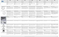
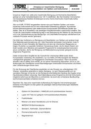
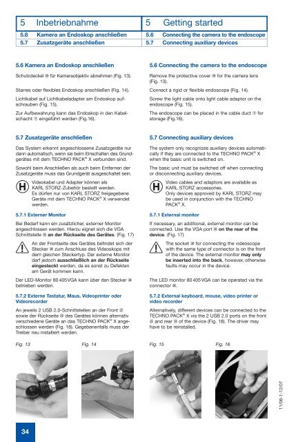
Schutzdeckel 5) für Kameraobjektiv abnehmen (Fig. 13).<br />
Starres oder flexibles Endoskop anschließen (Fig. 14).<br />
Lichtkabel auf Lichtkabeladapter am Endoskop aufschrauben<br />
(Fig. 15).<br />
Zur Aufbewahrung kann das Endoskop in den Kabel -<br />
schacht J eingeführt werden (Fig.16).<br />
5.7 Zusatzgeräte anschließen<br />
Das System erkennt angeschlossene Zusatzgeräte nur<br />
dann automatisch, wenn sie beim Einschalten des Grund -<br />
gerätes mit dem <strong>TECHNO</strong> PACK ® X verbunden sind.<br />
Sowohl beim Anschließen als auch beim Entfernen der<br />
Zusatzgeräte muss das Grundgerät ausgeschaltet sein.<br />
Videokabel und Adapter können als<br />
KARL STORZ-Zubehör bestellt werden.<br />
Es dürfen nur von KARL STORZ freigegebene<br />
Geräte mit dem <strong>TECHNO</strong> PACK ® X verwendet<br />
werden.<br />
5.7.1 Externer Monitor<br />
Bei Bedarf kann ein zusätzlicher, externer Monitor<br />
angeschlossen werden. Hierzu eignet sich die VGA<br />
Schnittstelle 3^ an der Rückseite des Gerätes. (Fig. 17)<br />
An der Frontseite des Gerätes befindet sich der<br />
Stecker 2* zum Anschluss des Videoskops mit<br />
dem gleichen Steckertyp. Der externe Monitor<br />
darf jedoch ausschließlich an der Rückseite<br />
eingesteckt werden, da es sonst zu Defekten<br />
am Gerät kommen kann.<br />
Der LED-Monitor 80 405VGA kann über den Stecker 2*<br />
betrieben werden.<br />
5.7.2 Externe Tastatur, Maus, Videoprinter oder<br />
Videorecorder<br />
An jeweils 2 USB 2.0-Schnittstellen an der Front 2%<br />
sowie der Rückseite 3( des Gerätes können alternativ<br />
verschiedene Geräte an das <strong>TECHNO</strong> PACK ® X angeschlossen<br />
werden (Fig. 18). Gegebenenfalls muss der<br />
Treiber neu installiert werden.<br />
34<br />
5.6 Connecting the camera to the endoscope<br />
5.7 Connecting auxiliary devices<br />
5.6 Connecting the camera to the endoscope<br />
Remove the protective cover 5) for the camera lens<br />
(Fig. 13).<br />
Connect a rigid or flexible endoscope (Fig. 14).<br />
Screw the light cable onto light cable adaptor on the<br />
endoscope (Fig. 15).<br />
The endoscope can be placed in the cable duct J for<br />
storage (Fig.16).<br />
5.7 Connecting auxiliary devices<br />
The system only recognizes auxiliary devices automatically<br />
if they are connected to the <strong>TECHNO</strong> PACK ® X<br />
when the basic unit is switched on.<br />
The basic unit must be switched off when connecting<br />
or disconnecting auxiliary devices.<br />
Video cables and adaptors are available as<br />
KARL STORZ accessories.<br />
Only devices approved by KARL STORZ may<br />
be used in conjunction with the <strong>TECHNO</strong><br />
PACK ® X.<br />
5.7.1 External monitor<br />
If necessary, an additional, external monitor can be<br />
connected. Use the VGA port 3^ on the rear of the<br />
device. (Fig. 17)<br />
The socket 2* for connecting the videoscope<br />
with the same type of connector is on the front<br />
of the device. The external monitor may only<br />
be inserted into the back, however, otherwise<br />
faults may occur in the device.<br />
The LED monitor 80 405VGA can be operated via the<br />
connector 2*.<br />
5.7.2 External keyboard, mouse, video printer or<br />
video recorder<br />
Alternatively, different devices can be connected to the<br />
<strong>TECHNO</strong> PACK ® X via the 2 USB 2.0 ports on the front<br />
2% and rear 3( of the device (Fig. 18). The driver may<br />
have to be reinstalled.<br />
Fig. 13 Fig. 14 Fig. 15 Fig. 16<br />
11/06-1-12/07