IATTENZIONE - V-Tech Garage Equipment
IATTENZIONE - V-Tech Garage Equipment
IATTENZIONE - V-Tech Garage Equipment

You also want an ePaper? Increase the reach of your titles
YUMPU automatically turns print PDFs into web optimized ePapers that Google loves.
PAVIMENTO<br />
Il sollevatore deve essere installato su platea orizzontale di spessore<br />
minimo 150 mm realizzata in calcestruzzo dosato con resistenza<br />
di almeno 25 N/mm2.<br />
Il pavimento deve inoltre essere piano e ben livellato (10 mm di tolleranza<br />
sul livellamento).<br />
Nel caso di applicazioni particolari, interpellare il costruttore.<br />
MONTAGGIO<br />
ATTENZIONE<br />
DURANTE IL MONTAGGIO NON É AMMESSO<br />
NESSUN ESTRANEO AI LAVORI<br />
MONTAGGIO COLONNE<br />
1 - Sollevare in verticale la colonna comando e posizionarla nel<br />
punto di installazione prestabilito curando gli allineamenti col fabbricato.<br />
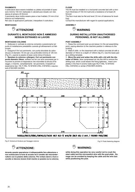
2 - Eseguire 6 fori sul pavimento, con punta elicoidale da calcestruzzo<br />
di diametro 18 mm per una profondità minima di 125 mm<br />
(Fig.31), usando la piastra di base come dima di foratura.<br />
3 - Spostare la colonna e allargare i fori sul pavimento con<br />
punta diametro 24mm, soffiare neI fori con aria compressa per rimuovere<br />
la polvere di trapanatura che ridurrebbe la tenuta di fissaggio,<br />
e inserire, completamente nel pavimento, 6 tasselli ad<br />
espansione tipo HILTI HSL-TZ M16/50 (HSL-3 M16/50) o equivalenti<br />
(FISCHER 24/25H).<br />
FLOOR<br />
The lift must be installed on a horizontal concrete bed with a minimum<br />
thickness of 150 mm built and a resistance of at least 25<br />
N/mm2.<br />
The floor must also be flat and level (10 mm of tolerance for levelling).<br />
Consult the manufacturer with regard to special applications.<br />
ASSEMBLY<br />
WARNING<br />
DURING INSTALLATION UNAUTHORISED<br />
PERSONNEL IS NOT ALLOWED<br />
POST ASSEMBLY<br />
1 - Raise the command post up and place it in the set assembling<br />
point, paying attention to the machine position in referece to the<br />
building.<br />
2 - Make 6 drills on the basement with a helical concrete bit with a<br />
diameter of 18mm to a depth of 125mm (fig.31). Use the basis pad<br />
as a drilling template.<br />
3 - Move the post and widen the drills with a bit with the diameter<br />
of 24mm, blow compressed air into the drill to remove the<br />
drilling dust, which could lessen the fixing tightness . Insert completely<br />
in the floor 6 anchor bolts type HILTI HSL-TZ M16/50<br />
HSL-3 M16/50) or similar (FISCHER 24/25H).<br />
Fig.31 Schema di foratura per fissaggio colonne<br />
Fig.31 Posts fastening diagram<br />
ATTENZIONE:<br />
durante questa operazione è indispensabile fare attenzione a<br />
non schiacciare la fune di acciaio ed il cavetto del microinterruttore<br />
con la piastra della colonna. Per evitare danni a fune e<br />
cavetto si devono tenere tirati mentre si posizio-na la colonna.<br />
WARNING:<br />
while doing this operation be very careful not to crush the<br />
steel cable and the microswitch wire with the post plate . Damage<br />
can be avoided by keeping the cable and the wire taut<br />
while positioning the post.<br />
20.