IATTENZIONE - V-Tech Garage Equipment
IATTENZIONE - V-Tech Garage Equipment
IATTENZIONE - V-Tech Garage Equipment

Create successful ePaper yourself
Turn your PDF publications into a flip-book with our unique Google optimized e-Paper software.
ALLACCIAMENTO IMPIANTO ELETTRICO<br />
ATTENZIONE<br />
Le operazioni sottoelencate devono essere eseguite<br />
da personale qualificato.<br />
1) Prima del collegamento elettrico verificare che :<br />
l’impianto di alimentazione al sollevatore sia dotato delle protezioni<br />
previste dalle norme vigenti nel paese in cui viene installato.<br />
la linea di alimentazione abbia la seguente sezione :<br />
Tensione sollevatore 400V trifase:............minimo 2,5 mm2<br />
Tensione sollevatore 230V trifase:............minimo 4 mm2<br />
Tensione sollevatore 230V monofase:......minimo 6 mm2<br />
le oscillazioni di tensione rientrino nel campo di tolleranza previsto<br />
dalle specifiche.<br />
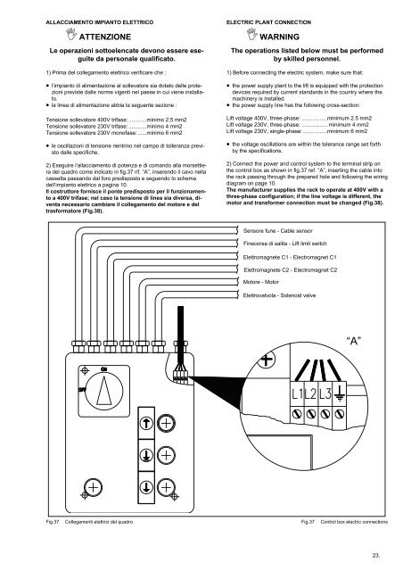
2) Eseguire l’allacciamento di potenza e di comando alla morsettiera<br />
del quadro come indicato in fig.37 rif. “A”, inserendo il cavo nella<br />
cassetta passando dal foro predisposto e seguendo lo schema<br />
dell’impianto elettrico a pagina 10.<br />
Il costruttore fornisce il ponte predisposto per il funzionamento<br />
a 400V trifase; nel caso la tensione di linea sia diversa, diventa<br />
necessario cambiare il collegamento del motore e del<br />
trasformatore (Fig.38).<br />
ELECTRIC PLANT CONNECTION<br />
WARNING<br />
The operations listed below must be performed<br />
by skilled personnel.<br />
1) Before connecting the electric system, make sure that:<br />
the power supply plant to the lift is equipped with the protection<br />
devices required by current standards in the country where the<br />
machinery is installed.<br />
the power supply line has the following cross-section:<br />
Lift voltage 400V, three-phase: .................minimum 2.5 mm2<br />
Lift voltage 230V, three-phase: ................. minimum 4 mm2<br />
Lift voltage 230V, single-phase: ................minimum 6 mm2<br />
the voltage oscillations are within the tolerance range set forth<br />
by the specifications.<br />
2) Connect the power and control system to the terminal strip on<br />
the control box as shown in fig.37 ref. “A”, inserting the cable into<br />
the rack passing through the prepared hole and following the wiring<br />
diagram on page 10.<br />
The manufacturer supplies the rack to operate at 400V with a<br />
three-phase configuration; if the line voltage is different, the<br />
motor and transformer connection must be changed (Fig.38).<br />
Sensore fune - Cable sensor<br />
Finecorsa di salita - Lift limit switch<br />
Elettromagnete C1 - Electromagnet C1<br />
Elettromagnete C2 - Electromagnet C2<br />
Motore - Motor<br />
Elettrovalvola - Solenoid valve<br />
“A”<br />
Fig.37<br />
Collegamenti elettrici del quadro<br />
Fig.37<br />
Control box electric connections<br />
23.