

A microstrip-fed cavity-backed circularly polarized horn antenna
A microstrip-fed cavity-backed circularly polarized horn antenna
A microstrip-fed cavity-backed circularly polarized horn antenna
- No tags were found...

You also want an ePaper? Increase the reach of your titles
YUMPU automatically turns print PDFs into web optimized ePapers that Google loves.
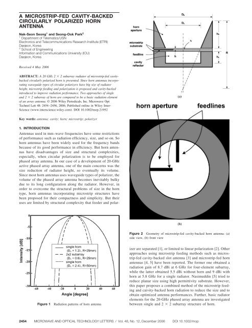
Figure 3Feeding network of 2 2 subarray2. SELECTION OF RADIATION ELEMENTIn the design of a basic radiation element for phased array <strong>antenna</strong>,there are two alternatives for chosen interelement distance, forexample, d 2.4 as follows:●●●a single <strong>horn</strong> with the aperture diameter d 2.4 as theradiatora2 2 subarray of four conical <strong>horn</strong>s as the basic radiatorelement with d h 1.2 Beam width of the conical <strong>horn</strong> with aperture diameter d h 1.2 do not practically change for different heights of R 29 mm at f 20.5 GHz. The half power beam width is equal to 3dB 53° 53°,and the radiation gain G 16.5 dB (Fig. 1). Predicted radiationpattern of a 2 2 radiation subarray of conical <strong>horn</strong>s with aperturediameter d h 1.2 is also shown in Figure 1. The width of the mainbeam of such radiator is 3dB 22° 22° and the gain G 16.5 dB.For a single conical <strong>horn</strong> with aperture diameter d h 2.4 fordifferent heights of the <strong>horn</strong> R at f 20.5 GHz, its radius is selectedas R 50 mm, for the main characteristics of the <strong>horn</strong> are stabilizedFigure 5 Predicted and measured results of 2 2 subarray: (a) radiationpattern (E-plane), (b) return lossfrom that value. In this case, the width of this beam pattern is 3dB 26° 30° and the gain is G 14.5 dB as compared in Figure 1.Analysis mentioned earlier draws a conclusion that the most usefulstructure to reduce the radiator height for the phased array radiator isa2 2 subarray of four radiators than a single <strong>horn</strong> of double size inheight and radius. The great decreasing of dimensional size of theradiator along its height is obtained.Figure 4 Picture of fabricated <strong>antenna</strong>. [Color figure can be viewed inthe online issue, which is available at www.interscience.wiley.com]3. ANTENNA DESIGNFigure 2 is a crosssectional view of the proposed <strong>antenna</strong> elementof <strong>microstrip</strong>-<strong>fed</strong> <strong>circularly</strong> <strong>polarized</strong> <strong>cavity</strong>-<strong>backed</strong> <strong>horn</strong>. The feednetwork and circular polarizer are implemented on the Duroid5880 substrate ( r 2.22, h 0.508 mm, tan 0.0009). Heightof the waveguide h h is selected based on R 29 mm. Diameter ofthe <strong>cavity</strong> D c is chosen by means of existence of the main wavetype of TE 11 mode in it. In our case, D c 0.75 . For the optimalexciting of the wave-guide resonator, it is necessary that thedistance between <strong>microstrip</strong> resonator and the bottom of the wave-DOI 10.1002/mop MICROWAVE AND OPTICAL TECHNOLOGY LETTERS / Vol. 48, No. 12, December 2006 2455


