

Internal PIFA for 2.4/5 GHz WLAN applications - Microwave and ...
Internal PIFA for 2.4/5 GHz WLAN applications - Microwave and ...
Internal PIFA for 2.4/5 GHz WLAN applications - Microwave and ...
- TAGS
- pifa
- wlan
- applications
- microwave

You also want an ePaper? Increase the reach of your titles
YUMPU automatically turns print PDFs into web optimized ePapers that Google loves.
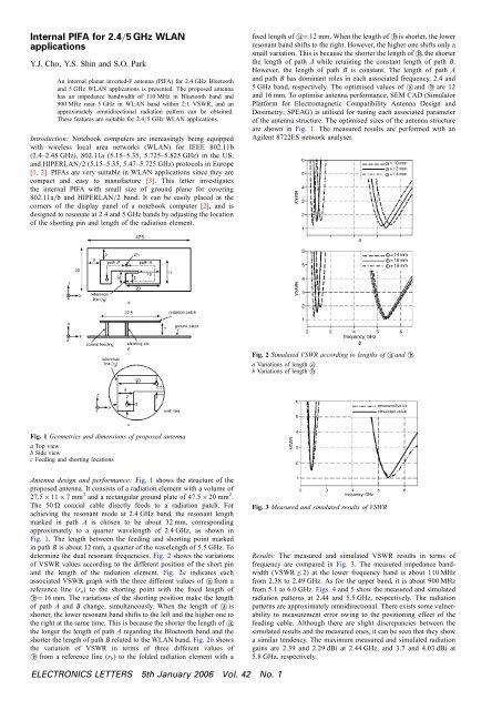
<strong>Internal</strong> <strong>PIFA</strong> <strong>for</strong> <strong>2.4</strong>=5 <strong>GHz</strong> <strong>WLAN</strong><strong>applications</strong>Y.J. Cho, Y.S. Shin <strong>and</strong> S.O. ParkAn internal planar inverted-F antenna (<strong>PIFA</strong>) <strong>for</strong> <strong>2.4</strong> <strong>GHz</strong> Bluetooth<strong>and</strong> 5 <strong>GHz</strong> <strong>WLAN</strong> <strong>applications</strong> is presented. The proposed antennahas an impedance b<strong>and</strong>width of 110 MHz in Bluetooth b<strong>and</strong> <strong>and</strong>900 MHz near 5 <strong>GHz</strong> in <strong>WLAN</strong> b<strong>and</strong> within 2:1 VSWR, <strong>and</strong> anapproximately omnidirectional radiation pattern can be obtained.These features are suitable <strong>for</strong> <strong>2.4</strong>=5 <strong>GHz</strong> <strong>WLAN</strong> <strong>applications</strong>.Introduction: Notebook computers are increasingly being equippedwith wireless local area networks (<strong>WLAN</strong>) <strong>for</strong> IEEE 802.11b(<strong>2.4</strong>–<strong>2.4</strong>8 <strong>GHz</strong>), 802.11a (5.15–5.35, 5.725–5.825 <strong>GHz</strong>) in the US,<strong>and</strong> HIPERLAN=2 (5.15–5.35, 5.47–5.725 <strong>GHz</strong>) protocols in Europe[1, 2]. <strong>PIFA</strong>s are very suitable in <strong>WLAN</strong> <strong>applications</strong> since they arecompact <strong>and</strong> easy to manufacture [3]. This letter investigatesthe internal <strong>PIFA</strong> with small size of ground plane <strong>for</strong> covering802.11a=b <strong>and</strong>HIPERLAN=2 b<strong>and</strong>. It can be easily placed at thecorners of the display panel of a notebook computer [2], <strong>and</strong> isdesigned to resonate at <strong>2.4</strong> <strong>and</strong> 5 <strong>GHz</strong> b<strong>and</strong>s by adjusting the locationof the shorting pin <strong>and</strong> length of the radiation element.fixed length of a ¼ 12 mm. When the length of b is shorter, the lowerresonant b<strong>and</strong> shifts to the right. However, the higher one shifts only asmall variation. This is because the shorter the length of b, the shorterthe length of path A while retaining the constant length of path B.However, the length of path B is constant. The length of path A<strong>and</strong> path B has dominant roles in each associated frequency, <strong>2.4</strong> <strong>and</strong>5 <strong>GHz</strong> b<strong>and</strong>, respectively. The optimised values of a <strong>and</strong>b are12<strong>and</strong> 16 mm. To optimise antenna per<strong>for</strong>mance, SEM CAD (SimulatorPlat<strong>for</strong>m <strong>for</strong> Electromagnetic Compatibility Antenna Design <strong>and</strong>Dosimetry; SPEAG) is utilised <strong>for</strong> tuning each associated parameterof the antenna structure. The optimised sizes of the antenna structureare shown in Fig. 1. The measured results are per<strong>for</strong>med with anAgilent 8722ES network analyser.Fig. 2 Simulated VSWR according to lengths of a <strong>and</strong> ba Variations of length ab Variations of length bFig. 1 Geometries <strong>and</strong> dimensions of proposed antennaa Top viewb Side viewc Feeding <strong>and</strong> shorting locationsAntenna design <strong>and</strong> per<strong>for</strong>mance: Fig. 1 shows the structure of theproposed antenna. It consists of a radiation element with a volume of27.5 11 7mm 3 <strong>and</strong> a rectangular ground plate of 47.5 20 mm 2 .The 50 O coaxial cable directly feeds to a radiation patch. Forachieving the resonant mode at <strong>2.4</strong> <strong>GHz</strong> b<strong>and</strong>, the resonant lengthmarked in path A is chosen to be about 32 mm, correspondingapproximately to a quarter wavelength of <strong>2.4</strong> <strong>GHz</strong>, as shown inFig. 1. The length between the feeding <strong>and</strong> shorting point markedin path B is about 12 mm, a quarter of the wavelength of 5.5 <strong>GHz</strong>. Todetermine the dual resonant frequencies, Fig. 2 shows the variationsof VSWR values according to the different position of the short pin<strong>and</strong> the length of the radiation element. Fig. 2a indicates eachassociated VSWR graph with the three different values of a from areference line (r a ) to the shorting point with the fixed length ofb ¼ 16 mm. The variations of the shorting position make the lengthof path A <strong>and</strong> B change, simultaneously. When the length of a isshorter, the lower resonant b<strong>and</strong> shifts to the left <strong>and</strong> the higher one tothe right at the same time. This is because the shorter the length of a,the longer the length of path A regardingtheBluetoothb<strong>and</strong><strong>and</strong>theshorter the length of path B related to the <strong>WLAN</strong> b<strong>and</strong>. Fig. 2b showsthe variation of VSWR in terms of three different values ofb from a reference line (r b ) to the folded radiation element with aFig. 3 Measured <strong>and</strong> simulated results of VSWRResults: The measured <strong>and</strong> simulated VSWR results in terms offrequency are compared in Fig. 3. The measured impedance b<strong>and</strong>width(VSWR 2) at the lower frequency b<strong>and</strong> is about 110 MHzfrom 2.38 to <strong>2.4</strong>9 <strong>GHz</strong>. As <strong>for</strong> the upper b<strong>and</strong>, it is about 900 MHzfrom 5.1 to 6.0 <strong>GHz</strong>. Figs. 4 <strong>and</strong> 5 show the measured <strong>and</strong> simulatedradiation patterns at <strong>2.4</strong>4 <strong>and</strong> 5.5 <strong>GHz</strong>, respectively. The radiationpatterns are approximately omnidirectional. There exists some vulnerabilityto measurement error owing to the positioning effect of thefeeding cable. Although there are slight discrepancies between thesimulated results <strong>and</strong> the measured ones, it can be seen that they showa similar tendency. The maximum measured <strong>and</strong> simulated radiationgains are 2.39 <strong>and</strong> 2.29 dBi at <strong>2.4</strong>4 <strong>GHz</strong>, <strong>and</strong> 3.7 <strong>and</strong> 4.03 dBi at5.8 <strong>GHz</strong>, respectively.ELECTRONICS LETTERS 5th January 2006 Vol. 42 No. 1


