

A Broadband T-Shaped Microstrip-line-fed Slot Antenna with ...
A Broadband T-Shaped Microstrip-line-fed Slot Antenna with ...
A Broadband T-Shaped Microstrip-line-fed Slot Antenna with ...
- No tags were found...

You also want an ePaper? Increase the reach of your titles
YUMPU automatically turns print PDFs into web optimized ePapers that Google loves.
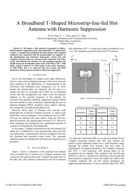
A <strong>Broadband</strong> T-<strong>Shaped</strong> <strong>Microstrip</strong>-<strong>line</strong>-<strong>fed</strong> <strong>Slot</strong><strong>Antenna</strong> <strong>with</strong> Harmonic SuppressionD. H. Choi, Y. J. Cho, and S. O. ParkSchool of Engineering, Information and Communications University103-6 Munji-dong, Yusong-Gu,Daejeon, KoreaAbstract-In this paper, a slot antenna is proposed to achieveboth harmonic suppression and wide bandwidth. To obtain theseresults, a T-shaped microstrip-<strong>line</strong>-<strong>fed</strong> slot antenna and U-shapedconductor <strong>line</strong> connected <strong>with</strong> the ground plane are applied. Atthe fundamental and harmonic frequencies, return loss andradiation characteristics are measured and compared <strong>with</strong> thoseof the conventional slot antenna. For the proposed antenna, the10-dB return loss bandwidth could reach 1220 MHz (1730 ~ 2950MHz), which is about 52 % <strong>with</strong> respect to the center frequencyof 2340 MHz, and it is observed that the second and thirdharmonics of the proposed antenna is effectively suppressed.<strong>with</strong> a thickness of H = 1.6 mm and a relative permittivity of ε r= 4.6. The simulation was performed <strong>with</strong> CST software.I. INTRODUCTIONDue to the advantages of compact sizes, high efficiencies,and low costs, active integrated antennas (AIAs) have attractedmuch attention in the applications of communication at themicrowave and millimeter-wave frequencies [1]. In AIAsdesign, the antenna plays an important role not only as aradiator but also as a resonator and a filter for an oscillationcircuit. But this configuration can easily occur the spuriousradiation at the resonant frequency of the antenna. Toovercome this problem, harmonic suppressed antenna (HAS)has been studied by many researchers, approaching the ways ofphotonic bandgap (PBG), circulator sector radiator, shortingpin, tuning stub, and split ground plane [2-4].However, these types of antennas can’t provide widebandwidth due to high Q of antenna structure. To improve thebandwidth, various topologies were introduced such as CPW<strong>fed</strong>loop slot antenna <strong>with</strong> some lattices along the feed <strong>line</strong>,dual-slot antenna, and stacked patch structure [5-7]. However,these techniques are attended by the complicated structure incommon for obtaining the wide bandwidth.In this paper, T-shaped microstrip-<strong>line</strong>-<strong>fed</strong> slot antenna [8],which has a modified slot in the ground plane and a merit foreasy fabrication, is demonstrated <strong>with</strong> the comparison betweenthe simulated and measured return losses. The measuredradiation patterns at fundamental and harmonic frequencies arepresented.II. ANTENNA DESIGNFigure 1 shows a schematic of the proposed slot antenna<strong>with</strong> a modified slot. It consists of a U-shaped conductor <strong>line</strong>connected <strong>with</strong> ground plane and T-shaped microstrip <strong>line</strong> onthe other side. This antenna is fabricated on the FR-4 substrateFigure 1. Geometry of the proposed antennaTABLE IOPTIMIZED PARAMETERS FOR THE PROPOSED ANTENNAparameterValue[mm]parameterValue[mm]W S 50 W D 8.6L S 21.2 W U 1L F 48.2 L D 3.5W F 3 L G 4.5To obtain the wide bandwidth, we use the slot antenna <strong>fed</strong> byT-shaped microstrip antenna since this type antenna canachieve a good impedance match over a wide frequency rangethorough the simple feed structure and also easily beimplemented. To suppress harmonics, the U-shaped conductor<strong>line</strong> (WU x LD) connected <strong>with</strong> ground plane in therectangular slot are applied. This conductor <strong>line</strong> and the gap(WD) act as the L-C resonator for filtering out the second andthird harmonic frequencies. Since the length and width of theU-shaped conductor <strong>line</strong> are the critical parameters forsuppressing the harmonics, we try to carefully adjust WU, WD,0-7803-9433-X/05/$20.00 ©2005 IEEEAPMC2005 Proceedings
Figure 3. Measured co-polarization patterns of the proposed antenna(solid <strong>line</strong> : 2500 MHz, dash-dot <strong>line</strong> : 5000 MHz, dot-dot <strong>line</strong> : 7500MHz)Figure 2. Simulated (dashed <strong>line</strong>) and measured (solid <strong>line</strong>) return lossesfor the proposed antennaand LD to achieve that L-C resonator has the wide band-stopcharacteristics. The optimized parameters are listed in Table I.III. EXPERIMENTThe simulated and measured return losses of the proposedantenna are shown in Figure 2. For the comparison, the graphof a conventional slot antenna <strong>fed</strong> by T-shaped microstrip <strong>line</strong>is also shown in the same figure. The basic structuralparameters of the conventional slot antenna are the same asthose of the proposed antenna except for the U-shapedconductor <strong>line</strong>. The center frequency of the conventional slotantenna has been designed around 2500 MHz. The bandwidthof about 960 MHz is reached and the bandwidth of the higherorder mode is about 2326 MHz. However, by fabricating theproposed antenna, these harmonics are completely suppressed,and also we obtain the 10-dB bandwidth of 1220 MHz(1730~2950 MHz), which is about 52 % <strong>with</strong> respect to thecenter frequency of 2340 MHz. In this experiment, attachingU-shaped conductor <strong>line</strong> on the ground plane does not result indeterioration of bandwidth but enhancing the bandwidth on thecontrary.Next, the co- and cross-polarization patterns at resonantfrequencies were measured for the proposed slot antenna. Thecross-polarized radiation patterns were normalized to themaximum value of co-polarization level. In the fundamentalfrequency, co-polarization patterns for the proposed antennaare similar to those of the y-directed dipole antenna, as shownin Figure 3. Both the second and third harmonics are measuredto be approximately less than -25 dB and -30 dB, respectively.This means that, at the harmonic frequencies, the radiationpatterns of the proposed antenna are drastically diminished.In Figure 4, E- and H-plane cross-polarization patterns forthe proposed antenna are presented. The H-plane crosspolarizationlevels compared to the E-plane one are somewhatincreased due to the unwanted current of the U-shapedconductor <strong>line</strong>. The measured maximum gains of the antennaFigure 4. Measured cross-polarization patterns of the proposed antenna(solid <strong>line</strong> : 2500 MHz, dash-dot <strong>line</strong> : 5000 MHz, dot-dot <strong>line</strong> : 7500MHz)are 4.3 dBi, 5.4 dBi, and 3.5 dBi at the frequencies of 2.0 GHz,2.5 GHz, and 3.0 GHz, respectively.IV. CONCLUSIONSA rectangular slot antenna <strong>fed</strong> by T-shaped microstrip <strong>line</strong> ispresented for achieving both harmonic suppression and widebandwidth. Since this proposed antenna consists of the U-shaped conductor <strong>line</strong> connected ground plane inside therectangular slot, it is easily fabricated. Experimental resultsindicate that the proposed antenna is quite effective forsuppressing the harmonics and enhancing the simultaneously.ACKNOWLEDGMENTThis work was supported by the National Research Lab.(NRL) of Ministry of Science and Technology, Korea, undercontact no. M1-0203-0015.REFERENCES[1] K. Chang, R. A. York, P. S. Hall, and T. Itoh, “Active integratedantenna,” IEEE Trans. Microwave Theory Tech., vol. 50, no. 3, pp. 937-944, March 2003.[2] Y. Horii and M. Tsutusmi, “Harmonic control by photonic bandgap onmicrostrip patch antenna,” IEEE Microwave & Guided Wave Lett., vol. 9,no. 1. pp. 13-15, January 1999.[3] V. Radisic, Y. Quan, and T. Itoh, “Class F power amplifier integrated<strong>with</strong> circular sector microstrip antenna,” IEEE MTT-s Int. MicrowaveSymp. vol. 2,.
[4] H. R. Kim, K. S. Hwang, K. K. Chang, and Y. J. Yoon, “A novel slotantenna for harmonic suppression,” Asia-Pacific Microwave Conference,2003.[5] Y. Horii and M. Tsutusmi, “Wide band operation of a harmonicallycontrolled EBG microstrip patch antenna,” IEEE <strong>Antenna</strong> & Prop.Society Int. Symp., vol. 3, pp. 16-21, 2002.[6] X. C. Lin and L. T. Wang, “A broadband CPW-<strong>fed</strong> loop slot antenna<strong>with</strong> harmonic control,” IEEE <strong>Antenna</strong>s and Wireless Propagat. Lett., vol.2, pp. 323-325, 2003.[7] H. R. Kim and Y. J. Yoon, “A novel wideband dual-slot antenna <strong>with</strong>harmonic suppression,” IEEE <strong>Antenna</strong> & Prop. Society Int. Symp., vol. 4,pp. 20-25, 2004.[8] M. K Kim, Y. H. Suh, and I. M. Park, “A T-shaped microstrip-<strong>line</strong>-<strong>fed</strong>wide slot antenna,” IEEE <strong>Antenna</strong> & Prop. Society Int. Symp., vol. 3, pp.1500-1503, 2002.


